
Related Manuals for AlienDVR DSD105

Summary of Contents for AlienDVR DSD105
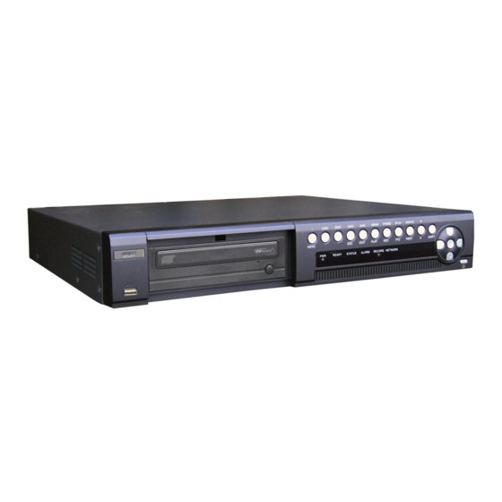
- Page 1 The new Alien Digital Video Recorder Operations Manual Model DSD105 4 Channel Real Time DVR Networkable Mobile Phone Monitoring Version 2.0...
-
Page 2: Table Of Contents
Table of Contents Page Welcome Important Safeguards and Warnings 1. Features Local functions 2. Installation 2.1 Checking the DVR and its Accessories 2.2 HDD Installation 2.3 Rear Panel Description 2.4 External Alarm In/Out 3. Operational Instructions 3.1 Front Panel 3.2 IR Controller 3.3 Menu Description 3.3.1 Menu Items 3.3.2 Menu Operation... - Page 3 5.14 Network Parameters 5.15 PTZ 6. Utilities 6.1 Default Parameters 6.2 Firmware 6.3 Hard Disk 6.4 Alarm Out 6.5 Reboot 6.6 Power Off 6.7 View Log 6.8 System Information 7. Firmware Upgrade 7.1 FTP Server Setup 7.2 Upgrade Mode 8. Web HTTP Operation 8.1 Network Connection 8.1.1 Login and Logout 9.
-
Page 4: Welcome
Welcome Thank you for purchasing our DVR! This operating manual is designed to be a reference tool for the installation and operation of your system. Here you can find information about this series DVR features and functions, as well as a detailed menu tree. Before installation and operation please read the following safeguards and warnings carefully! Important Safeguards and Warnings... -
Page 5: Features
The DSD105 has both the features of a digital video recorder and a digital video server. It works as a standalone unit or can be incorporated into a powerful surveillance network, suitable for use in banks, telecommunication, transportation, warehouse, clubs and public houses etc. -
Page 6: Installation
There is a list in the package. HDD Installation The DSD105 is not fitted with a Hard Drive unless purchased separately. The size of the Hard Drive can be calculated according to the total capacity required. A table is supplied at the end of this manual. -
Page 7: Rear Panel Description
Rear Panel Description This section provides information about the rear panel. When you install this series DVR for the first time, please refer to this part first. Function Description USB Port Not functional Video Inputs 4 Channels standard BNC Video Output Monitor 1 BNC Video Out Video Output Monitor 2 BNC Video Out... -
Page 8: External Alarm In/Out
External Alarm In/Out Connection Alarm Input Port: G (GND): Connect the GND sensor 1 ~ 3 : Alarm Input supporting normally open or normally closed. Alarm Output Port: 1 ~ : Relay Output Alarm Output Connection Please note the usage of jumper JJ1. If you use DC, either connection is okay. It is suggested that you use 12vDC at less than 1 Amp. -
Page 9: Operational Instructions
3. Operational Instructions Front Panel Type Name Description USB Port USB Port USB 2 Port DVD Writer DVD Writer DVD Writer Function Keys 1/MENU 1. Switch from preview mode to MENU mode. 2. WIPER control 3. Press MENU for >5secs to cancel beep sound. - Page 10 Type Name Description Function Keys 9WXYZ/PREV 1. Multi-screen preview switch 2. Switch MENU mode to PREVIEW FOCUS- in PTZ control 1. Input switch (number, lower case, upper case & symbol) 2. FOCUS+ in PTZ control 3. In Preview mode, display or hide the channel status bar.
-
Page 11: Ir Controller
IR Controller Name Description POWER Turn Off Device Enable/Disable IR Remote Control Numeric Keys Same as numeric keys on front panel EDIT Same as EDIT key on front panel Same as A key on front panel Same as REC key on front panel PLAY Same as PLAY key on front panel INFO... - Page 12 Loading the batteries in IR Controller Remove battery cover. Insert battery ensuring polarity correct. Replace battery cover. Start the IR Controller Press DEV key and input the DVR I.D (default is 88 but can be changed in the Display Menu and then press ENTER key. Check that the IR Status light is displaying green.
-
Page 13: Menu Description
Menu Description 3.3.1 Menu Items Menu Function Menu Function Unit name Camera name & position setup Device ID Adjust brightness, contrast, hue Require Password and saturation Screen Saver OSD display mode, position Display Video Standard Camera and OSD format setup Brightness Mask area setup Menu transparency... -
Page 14: Menu Operation
3.3.2 Menu Operation How to enter menu mode Press MENU key to enter DVR Main menu Press PLAY key to enter Playback menu Press REC key to enter Manual Record menu Press PTZ key to enter PTZ control interface. Special Note: You must input username and password. The default username is admin and the password is 12345. -
Page 15: Basic Operation Guide
Basic Operation Guide Username and Password This DVR is supplied with a default user of admin and password of 12345 You cannot change the admin username but the password can be modified. The Login dialogue box is shown below: Press right arrow key to enter password box. - Page 16 To add a new user and password press the Add button and enter username. Now enter the Password and verify by re-entering password. SPECIAL NOTE: Please refer to section 5 regarding the setting of access rights. If these rights are not set then new users will not be able to operate this DVR.
-
Page 17: Ptz Control
PTZ Control In preview mode press PTZ key and in login mode select username and password. You can now enter the PTZ control interface. Note that the user must have the PTZ control rights set. In menu mode press the PTZ menu.. There is a PTZ Control prompt in the PTZ control interface. - Page 18 Adjust Preset Number In PTZ control mode, press the REC/SHOT key, and then press the preset number (three numeric keys) and the relevant preset can be selected. Press REC/SHOT key again and change the preset number. When you exit PTZ control mode, the camera will stay at the current position.
-
Page 19: Manual Record
Manual Record The user must have the corresponding rights to use this facility. In preview mode press the REC key and enter the username and password to enter the Manual Record interface. In menu mode press the REC key to enter Manual Record directly. Channel: Lists the channel numbers available on this DVR Status:... -
Page 20: Playback
Playback The user must have playback rights. In preview mode press the PLAY key, select username and password to enter playback interface. In menu mode press the PLAY key and enter playback interface directly. Note that this DVR only supports one channel playback. Chan: keys to select one channel. - Page 21 Backup Devices: You can select USB memory stick, USB HDD, USB CD-R/W or IDE CD-R/W to backup files. Copy: Starts backup Backup Today: Backup all recorded files from today. There are two kinds of playback mode. Search and playback file, and playback by time.
-
Page 22: Backup Recorded Files
Backup Recorded Files NOTE: The user must have the necessary playback rights. Before starting the backup process ensure that the backup device is connected to the unit. In playback mode you can backup recorded files. In preview mode press the PLAY key and log in to enter the playback interface. - Page 23 ticked. You can use the same method to select other files to backup. When you have selected the files to backup go to the next step. At this point select the required backup device. You can select from the following devices: USB memory stick, USB CD-R/W or IDE CD- R/W.
-
Page 24: Shutdown Dvr
Shutdown DVR NOTE: Do not power off the unit by removing the mains supply as this may damage the Hard Drive fitted. Always use the Power Off facility in the Utilities menu or press the Power key on the front panel or on the I.R Controller. Shutdown DVR normally Using the Menu Enter the Utilities menu and press Power Off button. -
Page 25: Parameter Setup Guide
Parameter Setup Guide NOTE: Only users with Parameters Setup rights can access these menus. When the following parameters are modified and saved you must reboot the DVR to make the new parameters effective. Other parameters do not need a reboot. •... -
Page 26: Add And Delete User
same, the password will be saved. If password and verify password are not the same a warning message will be displayed. If this occurs then press Enter to return to password edit box and reinput new password again. Add and Delete user Add user Enter the User Management menu. - Page 27 Setup the password for a new user When you add a new user the password field is blank. If you do not want to change the password you can ignore this step. In the users list box in the User Management menu, use the up and down arrow keys to select the new username and then use the right arrow key to enter the password edit box.
- Page 28 rights appertaining to this username. These include local playback, remote playback and log access etc. If you wish to reduce these rights select the Set Privileges button. Use the left and right arrow keys to move to the appropriate rights, then press Enter or Edit key to enable or disable the facility.
-
Page 29: Device Id
Remote Watch Administrator can set remote preview rights for each channel Delete User In the User Management menu you can use the up and down arrows to select one user, then use the right arrow key to select the DEL button. If you then press the Enter button a confirmation dialogue box is displayed and pressing the Confirm button deletes the selected user. -
Page 30: Video Output Standard
Video Output Standard and VGA Setup Video Output Standard This DVR will support PAL or NTSC video output. Set the video output to match the video input standard by selecting the Video Standard box with the up and down arrow keys and selecting PAL or NTSC. PAL is the standard used in the U.K. - Page 31 Display Position and format Move to the Position button and press Enter to enter setup image. Here you will find there are 22 x 18 small panes with the OSD position marked in red. Use the arrow keys to move to the required OSD position. Press Edit key to select OSD format The following OSD formats are provided: MM DD YYYY W hh:mm:ss (default)
-
Page 32: Camera Input Adjustment - Camera Settings
Camera Input Adjustment – Camera settings In order to set the camera and background light levels to provide the best video images you need to set the video parameters such as brightness, saturation, contrast and hue. If you select the Camera menu and then Colour Setup you can set the brightness, saturation, contrast and hue settings. -
Page 33: View Tampering Alarm
The following screen is displayed: Move the yellow square using the mouse to where you wish to exclude video capture. Now press the left mouse key and Edit button and use the arrow keys to set the first area. Press Edit again to save the mask area. The maximum mask area is 8 x 8 panes and the minimum size is one pane. -
Page 34: Video Loss Alarm
Setup Alarm Policy The DVR will react to the Policy set. You can select one or more options from the following: On Screen Warning, Audible warning, Upload to Center and Trigger Alarm Output. Use the mouse to change the cross to a tick. Ensure the Confirm button is pressed to save the settings. -
Page 35: Motion Detection Alarm
5.10 Motion Detection Alarm This function provides an alarm when motion detection is triggered. Select the Camera menu and the above menu is displayed. Select Motion Det. Level which is the motion detect sensitivity. There are seven options. 0 is the lowest to 5 the highest and Off. - Page 36 The outer area has been set for motion detection. The centre blue box is the non-detectable motion area. If you click on the Motion Det. Level Policy the Motion Alarm Handle menu is displayed: Motion Alarm Recording When motion detection is activated you need to set the record channels in the Motion Alarm Handle menu.
-
Page 37: Preview Properties
5.11 Preview Properties In the preview menu you can setup preview mode, screen switch time, enable or disable audio preview and preview layout. Now click on Preview Setup and enter the Preview menu shown below. Preview Mode If you click on Preview Mode you can switch between a single channel display and four channel display. -
Page 38: Recording Setup
Audio Preview If you enable Audio Preview by clicking on the X and changing it to a tick, when you preview a single camera, the DVR will play the audio of that channel. Display Delay The Display Delay time can be set between 1 second and 10 seconds. If you set the On Screen Warning option, when several cameras are alarmed, the DVR will show these camera images one by one for the display delay time period. - Page 39 Select Camera Use the up and down arrow keys to select the appropriate channel. Stream Type There are two options Audio&Video and Video. Select Audio&Video if you want both audio and video otherwise select Video only. You must reboot unit to make this parameter effective.
-
Page 40: External Alarm Input And Relay Output
When the Schedule menu is entered as shown above, the Day should be selected. All Day If ALL Day is selected then the Period Times are switched off as recording will not be scheduled . If ALL Day is not selected and marked as disabled X, then the Period Times are enabled. - Page 41 Select Alarm In Click on this function to select alarm 1 through 4. Alarm Type Select N.O (normally open) or N.C (normally closed) Alarm Handling Select Handle or Ignore. Handle will display the Policy and PTZ Linkage options. Policy Select Policy and the Alarm in Handling menu will be displayed as follows: Record Camera Select the camera channels to record by clicking on the camera numbers changing the X disable to enabled ticked.
- Page 42 If On Screen Warning is selected and an alarm is triggered and DVR is in preview mode, the DVR will display an image of the related camera. If more than one camera is triggered, the DVR will display them one by one every 10 seconds.
- Page 43 Press Confirm button to save and return to Alarms menu. Press Cancel or ESC to abort to return to Alarms menu. Copy to Alarm In You can copy contents of this alarm settings to other channels. Select the channel. Copy Click on this option to start the above copy.
- Page 44 This menu allows you to set the alarm out schedule times. Select the day of the week for the alarm output Start Time/End Time You can select four periods in any one day. Do not overlap times and set times consecutively.
-
Page 45: Network Parameters
Exceptions The following exception events can be set to trigger an alarm: HardDiskFull, NTSC/PALDiffer, IllegalAccess, IPAddrConflict, NetworkFailure and HardDiskError. These events can be viewed on the Log. The following are triggered: Audible Warning DVR will beep. Upload to Center Send exception information to center host P.C Trigger Alarm Out Trigger local relay output AlarmOut1... - Page 46 Set the IP address in the DVR. The IP set by the manufacturer must be changed. Refer to the later section on setting up a network. If there is a DHCP server in the network you can set the IP as 0.0.0.0 then Confirm and the unit will automatically reboot using DHCP to dynamically assign an IP address, Mask and Gateway.
-
Page 47: Ptz
NIC Type The default is 10M/100M Auto. Other options that can be selected are: 10M Half-Duplex, 10M Full-Dup, 100M Half-Duplex and 100M Full-Dup. Half duplex allows send and receive serially whereas full duplex allows both send and receive at the same time. IP Server IP Server address. - Page 48 Data Bits/Stop Bits/Parity/Flow Control These need to be set for the appropriate PTZ camera. Protocol Select the necessary protocol used by the PTZ. There is a large list of protocols from which to select. PTZ Addr Set each camera with a different address. It is easier to use the same camera channel number.
- Page 49 The sequence number will consist of a maximum of 16 presets. Each tour or cruise will have to be given a different sequence number. Each preset can be allocated a dwell speed and dwell time. The dwell time is the time the presets waits before starting a move to the next preset.
-
Page 50: Utilities
Utilities Click on the Utilities menu to display the following: Ensure you have the rights to access this menu. Default Parameters This option allows you to restore the manufacturers settings. Note that the IP address, Gateway and Port number will not be restored. Click Confirm to proceed. -
Page 51: Firmware
Firmware You can use this option to upgrade the system firmware. Please read section 7 before progressing. You can select one of two methods to upgrade the firmware. Select either FTP or USB. If you select FTP mode you will enter the FTP Upgrade menu. Input the FTP server IP address and then press Enter. -
Page 52: Hard Disk
Hard Disk This menu provides information about the hard drives. This includes capacity, free space, standby or not and whether the status is normal or not. Format You must stop all recording before formatting the drives. After formatting you must reboot the DVR otherwise it will not perform correctly. Enter Confirm to complete the format. -
Page 53: Alarm Out
Alarm Out This menu option allows you to clear the alarm output manually. Enter Confirm to proceed. Reboot This menu option allows you to reboot the DVR. Power Off This menu option allows you to power off the DVR. View Log This menu option allows you to view the Log menu. - Page 54 Alternatively you can search options by the following: By Type, By Time or By Type&Time By Type This option displays log information according to the assigned type. The type is divided into either Major Type or Minor Type. Major Type includes Operation, Alarm, Exception and All.
-
Page 55: System Information
By Time This option allows you to view between one time period. Select By Time in the Query box and select Start and Stop times. Press SearchLog button and then press Enter to start searching. DVR will display matched log information. Press Return to return to the Utilities menu. -
Page 56: Firmware Upgrade
Firmware Upgrade The DVR firmware is stored on a Flash ROM. You can use the DVR upgrade function to write the firmware onto flash. There are two instances when the firmware needs to be loaded. One is to update old firmware and the other is to reload code in the DVR due to corruption. - Page 57 Create a new user. Select New User and a dialogue box will be displayed. Input a user name of target and click okay. In the Change Password box input password in the New Password field and again in the Verify Password filed. Click OK to save and exit this box.
-
Page 58: Upgrade Mode
Upgrade Mode There are three methods for upgrading the DVR firmware. These are as follows: You can use the client software to upgrade the firmware file. You do not need to use the ftp server software. Please refer to the client software user manual for detailed information. -
Page 59: Web Http Operation
Web HTTP Operation Please note, all the operations here are based on our 4-ch DVR. There may be differences in the interface due to different models. Network connection Before web HTTP operation, please check the following items: l Network connection is correctly configured l DVR and PC network setup is correct. -
Page 60: Networking A Digital Video Recorder
9. Networking a Digital Video Recorder 9.1 Configure the DVR to operate with a modem router. For experienced Users Configure the DVR as follows: a. It is assumed you have a PC working on Broadband Internet. b. Check IP address in P.C and record IP Address, Subnet Mask & Gateway Address. -
Page 61: For Beginners
9.2 For Beginners Only 1 Does the site already have How many PCs need access or require Internet access ? to the DVR ? Option 1 More than 1 Option 2 Option 3 You must be able to perform some basic tasks in order to connect your Digital Video Recorder to a PC and subsequently the Internet. -
Page 62: How Do I Set My Pc To Obtain An Ip Address Automatically
9.2.1 How do I set my PC to ‘ Obtain an IP address automatically’ ? • Control Panel, • Network Connections, • Local Area Connection, • Properties, • Internet Protocol (TCP/IP), • Properties, • Select ‘ Obtain IP Address Automatically’ 9.2.2 How do I set my PC’... -
Page 63: How Do I Configure A Router For Remote Access
9.2.5 How do I Configure a Router for Remote Access ? • Instructions on the SystemQ website cover the NET800 and Netgear Routers 9.2.6 How do I find the On-Line Support ? http://www.systemq.com/cgi-bin/commerce.exe?display=user2 Detailed descriptions are available there for all these questions plus more besides, including …... -
Page 64: Option 1: Connect A Dvr Directly To A Single Pc
9.3 Option 1: Connect a DVR directly to a single PC Figure 1 Computer Digital Video Recorder RJ45 cross over cable IP Address = 192.168.1.108 Subnet Mask = 255.255.255.0 IP Address = 192.168.1.10 Subnet Mask = 255.255.255.0 Tasks : • Configure network settings in DVR manually •... -
Page 65: Option 2: Connect A Dvr To A Switch Or Hub
9.4 Option 2: Connect a DVR to a switch or hub Figure 2 Computer No 1 Switch or Hub 1 2 3 4 5 6 7 8 9 101112 10M100M UPLINK patch cable SWITCH 131415 161718192021 222324 IP Address = 192.168.1.10 Subnet Mask = 255.255.255.0 Computer No 2 patch cable... -
Page 66: Option 3: Connecting For Internet Access
9.5 Option 3: Connecting for Internet Access Figure 3 Telephone Computer 1 2 3 4 5 6 7 8 9 BT Wall Socket ADSL Filter Ideally : Set PC to Obtain IP Address Automatically Alternatively : RJ11 cable with IP Address = 192.168.1.10 BT Adapter Subnet Mask = 255.255.255.0 Gateway = 192.168.1.1... -
Page 67: Network Cable Connections
Tasks : • Find out what the external IP address is, this is assigned by the customer’ s Internet Service Provider • Find out : is this a fixed IP address, ie: “ Static, or does it change, ie: “ Dynamic” ? •... -
Page 68: Appendix A Hard Disk Capacity Information
Appendix A Hard Disk Capacity Information Rather than use the earlier Disk Recording Schedule for timings and if you are mathematically minded you may wish to use the following formulae to calculate storage capacity. This information has been provided by the manufacturer and we are unable to provide support on this data. -
Page 69: Appendix B Recording Timetable
Appendix B - DVR Recording Times in Days FPS Gb/Hr Gb/Hr Channel Machine 80Gb 160Gb 250Gb 300gb 400Gb 750Gb 10.7 12.8 17.1 32.1 11.2 13.4 17.9 33.5 13.2 15.8 21.1 39.5 12.9 20.1 24.2 32.2 60.4 17.4 27.1 32.5 43.4 81.3 13.3 26.6... -
Page 70: Appendix C Specifications
Appendix C - Specifications Model Number DSD105 Alien DVR Video Compression MPEG4/H264 Resolution PAL: 352 * 288 CIF 176 * 144 QCIF Playback Resolution CIF / QCIF Video Input 4 channels Video Input Interface BNC 1.0v p~p 75 ohms Video Output...
Need help?
Do you have a question about the DSD105 and is the answer not in the manual?
Questions and answers