Nortel 201i Maintenance And Diagnostics
Callpilot
Hide thumbs
Also See for 201i:
- Hardware installation (178 pages) ,
- Installation and configuration manual (148 pages) ,
- Upgrade manual (126 pages)

Related Manuals for Nortel 201i


Summary of Contents for Nortel 201i
- Page 1 201i Server Maintenance and Diagnostics CallPilot Release 4.0 Document Number: 555-7101-119 Document Version: Standard 1.05 October 2006...
- Page 2 Nortel Networks. The process of transmitting data and call messaging between the CallPilot server and the switch or system is proprietary to Nortel Networks. Any other use of the data and the transmission process is a violation of the user license unless specifically authorized in writing by Nortel Networks prior to such use.
- Page 3 Symantec Corporation. QUICKTIME is a trademark of Apple Computer, Inc. RADISYS is a trademark of Radisys Corporation. ROLM is a trademark of Siemens ROLM Communications Inc. SLR4, SLR5, and TANDBERG are trademarks of Tandberg Data ASA. 201i Server Maintenance and Diagnostics...
- Page 4 WINZIP is a trademark of Nico Mark Computing, Inc. XEON is a trademark of Intel, Inc. Information for Japan Japan VCCI statement The following applies to server models 1005r, 703t, 201i, and 1002rp: この装置は、情報処理装置等電波障害自主規制協議会 (VCCI) の規定に基づくク ラス A 装置です。この装 置を家庭環境で使用すると電波妨害を引き起こすこと があります。この場合には使用者が適切な対策を取るように要求されることがあ...
- Page 5 October 2006 Publication history Publication history October 2006 CallPilot 4.0, Standard 1.05 of the 201i Server Maintenance and Diagnostics is issued for general release. October 2006 CallPilot 4.0, Standard 1.04 of the 201i Server Maintenance and Diagnostics is issued to add a graphic.
- Page 6 Reporter Guide (555-7101-310) Maintenance Troubleshooting Guide (555-7101-501) Server Maintenance and Diagnostics 201i Server Maintenance and Diagnostics Guide (555-7101-119) 703t Server Maintenance and Diagnostics Guide (555-7101-227) 1002rp Server Maintenance and Diagnostics Guide (555-7101-206) 1005r Server Maintenance and Diagnostics Guide (555-7101-512) Symposium, M1/Succession 1000, and Voice Processing Guide (297-2183-909)
-
Page 7: Table Of Contents
Task List Troubleshooting your CallPilot system ......21 To determine why the 201i server failed the 8051 startup ....43 To determine why the 201i server failed to start CallPilot ....44 Using the operating system online diagnostic tools ..45 To use the operating system Event Viewer........ - Page 8 Task List Standard 1.05 Performing hardware maintenance and mechanical assembly ............119 To remove the server from the switch ........... 121 To replace the server ..............123 To remove the IDE hard drive ............129 To install the hard drive ..............133 To replace the software feature key ..........
- Page 9 Understanding fault management ....... . 64 201i Server Maintenance and Diagnostics...
- Page 10 Contents Standard 1.05 Section A: Tools for isolating and fixing hardware problems Overview........... 66 Alarm Monitor .
-
Page 11: How To Get Help
How to get Help This section explains how to get help for Nortel products and services. Getting Help from the Nortel Web site The best way to get technical support for Nortel products is from the Nortel Technical Support Web site: http://www.nortel.com/support This site provides quick access to software, documentation, bulletins, and tools to address issues with Nortel products. - Page 12 To access some Nortel Technical Solutions Centers, you can use an Express Routing Code (ERC) to quickly route your call to a specialist in your Nortel product or service. To locate the ERC for your product or service, go to: http://www.nortel.com/erc...
-
Page 13: About This Guide
C h a p t e r 2 About this guide In this chapter Maintenance and diagnostics overview Resolving system problems Replacing hardware components 201i Server Maintenance and Diagnostics... -
Page 14: Maintenance And Diagnostics Overview
About this guide Standard 1.05 Maintenance and diagnostics overview Introduction The maintenance and diagnostic activities discussed in this guide are divided into two groups of activities: troubleshooting and diagnostics (identifying the cause of and resolving system problems) performing hardware maintenance For a list of CallPilot documentation, see the document map on page 6. - Page 15 CallPilot software or rebuild the system. To locate instructions for these tasks, refer to the CallPilot Software Administration and Maintenance Guide (555-7101-202). 201i Server Maintenance and Diagnostics...
-
Page 16: Resolving System Problems
CallPilot Administrator’s Guide (555-7101-301) CallPilot Troubleshooting Guide (555-7101-501) Using this guide This guide provides instructions for using the resources provided by your 201i server, as follows: interpret the LEDs on the Chapter 3, “Troubleshooting your 201i server CallPilot system”... - Page 17 CallPilot server platforms, and ways to resolve them. Use the CallPilot Troubleshooting Guide to resolve the following types of problems: server boot cycle failures peripheral device problems monitor display problems server-to-network connection problems remote access connection problems CallPilot application problems 201i Server Maintenance and Diagnostics...
-
Page 18: Replacing Hardware Components
Before replacing any parts on your server, refer to the Nortel product catalog for the part codes. CAUTION Risk of system damage The use of parts that are not approved by Nortel can cause serious system problems or void your Nortel warranty. CallPilot... - Page 19 CallPilot Installation and Configuration Task List (555-7101-210) for the following information: required tools and equipment recommended safety precautions for electrostatic discharge, handling cards, and handling your server instructions for shutting down your 201i server or for taking it out of service 201i Server Maintenance and Diagnostics...
- Page 20 About this guide Standard 1.05 CallPilot...
-
Page 21: Troubleshooting Your Callpilot System
Status LEDs and HEX display location Interpreting the power status LED Interpreting the MPC slot LEDs Interpreting the network and drive activity LEDs Interpreting the HEX display Section B: Startup diagnostics Startup diagnostic codes Startup sequence description Troubleshooting startup problems 201i Server Maintenance and Diagnostics... -
Page 22: Overview
For more information, see “LED and HEX displays” on page 23. Startup sequence and diagnostic codes To help you determine if the 201i server started successfully (or if it failed), watch the startup sequence and the diagnostic codes that appear. The entire sequence occurs when you do one of the following: Lock the 201i server against the switch backplane. -
Page 23: Section A: Led And Hex Displays
Section A: LED and HEX displays In this section Status LEDs and HEX display location Interpreting the power status LED Interpreting the MPC slot LEDs Interpreting the network and drive activity LEDs Interpreting the HEX display 201i Server Maintenance and Diagnostics... -
Page 24: Status Leds And Hex Display Location
Troubleshooting your CallPilot system Standard 1.05 Status LEDs and HEX display location The following diagram shows the location of the status LEDs and HEX display on the 201i server’s faceplate. Power status LED MPC status LEDs MPC status LEDs HEX display... -
Page 25: Interpreting The Power Status Led
Interpreting the power status LED Introduction The power status LED is located on the 201i server faceplate, directly under the keyboard connector. The LED indicates whether it is safe to remove the server from the switch (which results in a server power down). - Page 26 Note: You must courtesy down CallPilot, and then shut down the operating system before you can remove the 201i server from the switch. For instructions, see “Powering down the server” in the CallPilot Installation and Configuration Task List. (555-7101-210)
-
Page 27: Interpreting The Mpc Slot Leds
October 2006 Troubleshooting your CallPilot system Interpreting the MPC slot LEDs Introduction There is an LED for each MPC slot on the 201i server. MPC slot LED functions The LEDs indicate two possible MPC slot states: The MPC is in use. -
Page 28: Interpreting The Network And Drive Activity Leds
Troubleshooting your CallPilot system Standard 1.05 Interpreting the network and drive activity LEDs Introduction The 201i server provides four LEDs to indicate ELAN Subnet, CLAN Subnet, SCSI device, and IDE hard drive activity. They are labeled as follows: LED label Description... - Page 29 Configuration Wizard. For instructions, refer to the CallPilot Manager online Help. blinking rapidly activity is occurring on the network. Note: This does not mean that the 201i server is actually transmitting or receiving packets. IDE drive LED states IF the I LED is THEN the IDE hard drive is idle.
-
Page 30: Interpreting The Hex Display
“Startup diagnostic codes” on page 36. For a description of the startup sequence, see “Startup sequence description” on page 40. HEX display codes During startup and normal 201i server operation, the HEX display on the server faceplate displays one of the codes in the following table: HEX display output... - Page 31 POST Terminal errors that result in a system halt do not appear on the HEX display. If you cannot use the HEX display to determine the cause of a system halt, contact your Nortel technical support representative. HOST This code appears during the startup sequence and means that BIOS diagnostics have started.
- Page 32 An alarm of unknown severity occurred. This error should not occur on a properly installed system. The severity of this event is treated as higher-than-critical. Note: If you observe “???” or anything else on the display, contact your Nortel technical support representative. CallPilot...
- Page 33 201i server from the switch. If you perform a cold restart by pressing and holding the Reset button for 2 seconds on the 201i server faceplate, or by removing and then reinserting the 201i server in the switch, the start sequence starts at stage 1, described on page 40.
- Page 34 Troubleshooting your CallPilot system Standard 1.05 CallPilot...
-
Page 35: Section B: Startup Diagnostics
October 2006 Troubleshooting your CallPilot system Section B: Startup diagnostics In this section Startup diagnostic codes Startup sequence description Troubleshooting startup problems 201i Server Maintenance and Diagnostics... -
Page 36: Startup Diagnostic Codes
Critical startup diagnostic codes All critical startup diagnostics must pass before the 201i can proceed with the start sequence. If a critical diagnostic fails, the start sequence indefinitely halts, an error code displays, and a continuous beep is heard. - Page 37 Status code Operation description Failure code HOST Continuation of BIOS diagnostics P:XX The monitor displays the BIOS start screen. If a noncritical error occurs, the server continues the start sequence. 201i Server Maintenance and Diagnostics...
- Page 38 Troubleshooting your CallPilot system Standard 1.05 Status code Operation description Failure code The operating system start sequence P:XX started Note: For a description, Note: If the CallPilot server software see “P:XX failure codes” is not installed, the HEX display on page 39. remains at NT.
- Page 39 POST Terminal errors that result in a system halt do not appear on the HEX display. If you cannot use the HEX display to determine the cause of a system halt, contact your Nortel technical support representative. 201i Server Maintenance and Diagnostics...
-
Page 40: Startup Sequence Description
The entire sequence occurs when you do one of the following: You lock the 201i against the switch backplane, and the 201i powers up. You press and hold the Reset button for 2 seconds on the 201i server faceplate to perform a hardware restart. - Page 41 End of system controller self-tests. No errors T:08 blinks were found. three times Approximate duration: less than 3 seconds Beginning of BIOS diagnostics HOST Note: The BIOS splash screen appears, and HOST scrolls across the HEX display. Approximate duration: 7 seconds 201i Server Maintenance and Diagnostics...
- Page 42 Information box appears, click OK unless you want a reminder to configure the server. Completion of operating system start sequence. The 8051 system controller is running normally. The 201i CallPilot software loads. One of the following, as OK means that CallPilot has loaded. applicable: CallPilot Fault Management takes over.
-
Page 43: To Determine Why The 201I Server Failed The 8051 Startup
On rare occasions this too may not function properly. If this situation occurs and the faceplate reset button fails to reboot, you will need to unseat the 201i from the PBX shelf (followed by a re-insertion) in order to initiate the Windows reboot. -
Page 44: To Determine Why The 201I Server Failed To Start Callpilot
Note: Allow 5 minutes for the start cycle to complete. 5 Refer to the CallPilot Troubleshooting Guide for other suggestions. 6 If you still cannot find the cause of the failure, call your Nortel technical support representative. To determine why the 201i server failed to start CallPilot 1 Make a note of any diagnostic codes. -
Page 45: Using The Operating System Online Diagnostic Tools
C h a p t e r 4 Using the operating system online diagnostic tools In this chapter Overview Viewing event logs Using TCP/IP diagnostic tools 201i Server Maintenance and Diagnostics... -
Page 46: Overview
Using the operating system online diagnostic tools Standard 1.05 Overview Introduction This section describes how to access the runtime online diagnostic tools provided by the operating system server software. Use these tools when a serious problem prevents the use of the CallPilot diagnostic tools that are available in CallPilot Manager. - Page 47 Using the operating system online diagnostic tools nbtstat netstat These utilities help you to verify network connectivity. They help you to thoroughly test the network interface and isolate any configuration problems. Network connectivity is essential to CallPilot operation. 201i Server Maintenance and Diagnostics...
-
Page 48: Viewing Event Logs
To determine what happened, you can use the following: operating system Event Viewer on the 201i server (see “To use the operating system Event Viewer” on page 50) CallPilot Event Browser or Alarm Monitor in CallPilot Manager For more information, do one of the following: See “Alarm Monitor”... - Page 49 Where to get more information For more information about using the operating system Event Viewer, click ➝ Help Contents in the Event Viewer window. See also “To use the operating system Event Viewer” on page 50. 201i Server Maintenance and Diagnostics...
-
Page 50: To Use The Operating System Event Viewer
Using the operating system online diagnostic tools Standard 1.05 To use the operating system Event Viewer ➝ ➝ ➝ 1 Click Start Programs Administrative Tools Event Viewer. Result: The Event Viewer window appears. CallPilot... - Page 51 2 To view a log, click the name of the log in the left frame of the window. The illustration shows an example of the Application log. An example of a System log appears in the following illustration. Note: The Security log available only to administrators is not shown. 201i Server Maintenance and Diagnostics...
- Page 52 Application log illustration on page 51. 5 Use the error description to help determine how to resolve errors. Note: If the error persists or does not suggest a solution, contact your Nortel support representative. 6 Click Close. Result: The event log reappears.
-
Page 53: Using Tcp/Ip Diagnostic Tools
The ipconfig command displays IP configuration information. Ipconfig default If you run the command without flags, it displays the IP address, subnet mask, and default gateway for each adapter bound to TCP/IP. Ipconfig command syntax ipconfig /[ ] 201i Server Maintenance and Diagnostics... -
Page 54: To Run The Ipconfig Command From The Operating System
Using the operating system online diagnostic tools Standard 1.05 The following flags are available for the ipconfig command: Flag Description Displays Help information. /all Displays full configuration information. /release Releases the IP address for the specified adapter. /renew Renews the IP address for the specified adapter. To run the ipconfig command from the operating system ➝... - Page 55 Record route for count hops -s count Time stamp for count hops -j host-list Loose source route along host list -k host-list Strict source route along host list -w timeout Time-out in milliseconds to wait for each reply 201i Server Maintenance and Diagnostics...
-
Page 56: To Run The Ping Command From The Operating System
Using the operating system online diagnostic tools Standard 1.05 To run the ping command from the operating system ➝ ➝ ➝ 1 Click Start Programs Accessories Command Prompt to display the command prompt window. Result: The Command Prompt window appears. 2 At the prompt, type ping <destination IP address>... -
Page 57: To Run The Tracert Command From The Operating System
2 At the prompt, type the following command: tracert [-d] [-h maximum_hops] [j host_list] [-w timeout] [target name] Example: tracert 200.286.0.32 210 200.236.0.04 3 Press Enter. Result: The system runs the tracert utility. 4 Type Exit to exit the Command Prompt window. 201i Server Maintenance and Diagnostics... - Page 58 Using the operating system online diagnostic tools Standard 1.05 The arp command The arp command displays and modifies the IP-to-physical address translation tables used by Address Resolution Protocol (arp). Arp command syntax The arp command uses the following syntax: arp -s inet_addr eth_addr [if_addr] arp -d inet_addr [if_addr] arp -a [inet_addr] [-N if_addr] Parameter...
-
Page 59: To Run The Arp Command From The Operating System
Nbtstat command syntax The nbtstat command uses the following syntax: nbtstat [-a remotename] [-A IP address] [-c] [-n] [-R] [-r] [-S] [-s] [interval] Parameter Description -a remotename Lists the remote computer’s name table using its name. 201i Server Maintenance and Diagnostics... - Page 60 Using the operating system online diagnostic tools Standard 1.05 Parameter Description -A IP address Lists the remote computer’s name table using its IP address. Lists the contents of the NetBIOS name cache giving the IP address of each name. Lists local NetBIOS names. Registered indicates that the name is registered by broadcast (Bnode) or WINS (other node types).
-
Page 61: To Run The Nbtstat Command From The Operating System
Displays addresses and port numbers in numerical form. Displays per-protocol statistics. -p proto Shows connections for the protocol specified by proto. Proto can be tcp or udp. If used with the -s option, proto can be tcp, udp, or ip. 201i Server Maintenance and Diagnostics... -
Page 62: To Run The Netstat Command From The Operating System
Using the operating system online diagnostic tools Standard 1.05 Displays the contents of the routing table. interval Displays selected statistics, pausing between each display. Press Ctrl+C to stop displaying. To run the netstat command from the operating system ➝ ➝ ➝... -
Page 63: Using Callpilot Manager To Monitor Hardware
Introducing the Maintenance page Viewing component states Starting and stopping components Running integrated diagnostics Viewing the last diagnostic results Section C:Working with the Multimedia and Channel Monitors Working with the Multimedia Monitor Working with the Channel Monitor 201i Server Maintenance and Diagnostics... -
Page 64: Understanding Fault Management
Using CallPilot Manager to monitor hardware Standard 1.05 Understanding fault management Introduction Fault management is a term that describes how the CallPilot server detects and notifies you of potential or real hardware problems (faults). The server processes events to detect hardware problems and raises alarms to notify you when these problems occur. -
Page 65: Section A: Tools For Isolating And Fixing Hardware Problems
October 2006 Using CallPilot Manager to monitor hardware Section A: Tools for isolating and fixing hardware problems In this section Overview Alarm Monitor Event Browser Maintenance page Channel and Multimedia Monitors 201i Server Maintenance and Diagnostics... -
Page 66: Overview
Using CallPilot Manager to monitor hardware Standard 1.05 Overview Introduction This section provides guidelines on how to use the CallPilot Manager tools to detect, isolate, and fix potential or real hardware problems. Component dependencies The status of some components is dependent on the operational status of other components. - Page 67 October 2006 Using CallPilot Manager to monitor hardware system administrator logon difficulties alert icons on the Maintenance page 201i Server Maintenance and Diagnostics...
-
Page 68: Alarm Monitor
Using CallPilot Manager to monitor hardware Standard 1.05 Alarm Monitor Introduction Use the Alarm Monitor to investigate one or more raised alarms. About alarms Alarms are warnings generated by events. Alarms communicate the same information as events. However, alarms are reported in the Alarm Monitor instead of the Event Browser, and are managed differently than events: Alarms appear in the Alarm Monitor only for Minor, Major, and Critical events (not Information events). -
Page 69: To Investigate Using The Alarm Monitor
5 Repeat steps 3 and 4 to view more alarms, if necessary. 6 If the solution to the problem is not apparent, obtain the return code of the first event and continue the investigation by using the Event Browser (see “Event Browser” on page 71). 201i Server Maintenance and Diagnostics... - Page 70 Using CallPilot Manager to monitor hardware Standard 1.05 See also For detailed information on how to use the Alarm Monitor, refer to the CallPilot Administrator’s Guide (555-7101-301), or the CallPilot Manager online Help. CallPilot...
-
Page 71: Event Browser
Each event identifies the time the event occurred, the object that generated the event, and the cause of the event. Events are classified as Information, Minor, Major, or Critical. By default, the Event Browser displays only the latest 100 critical events. 201i Server Maintenance and Diagnostics... -
Page 72: To Investigate Using The Event Browser
Result: A description of the event appears in a new web browser window. 4 View the description and recovery action. 5 Repeat steps 3 and 4 to view more events, if necessary. 6 If the solution to the problem is not apparent, contact your Nortel technical support representative. CallPilot... - Page 73 Using CallPilot Manager to monitor hardware See also For detailed information on how to use the Event Browser (for example, how to set preferences), refer to the CallPilot Administrator’s Guide (555-7101-301) or the CallPilot Manager online Help. 201i Server Maintenance and Diagnostics...
-
Page 74: Maintenance Page
Using CallPilot Manager to monitor hardware Standard 1.05 Maintenance page Introduction Use the Maintenance page to get status information for any suspect components. If you suspect or discover a problem with hardware such as an MPC-8 card, or the DS30X link, you can use the Diagnostic section on the Maintenance page. -
Page 75: Channel And Multimedia Monitors
Disabling call channels If you must take the CallPilot system out of service to perform software or hardware maintenance, Nortel recommends that you disable all call channels first. There are two ways to disable the call channels: Courtesy stop the channels (preferred method). - Page 76 Using CallPilot Manager to monitor hardware Standard 1.05 CallPilot...
-
Page 77: Section B: Working With The Maintenance Page
Using CallPilot Manager to monitor hardware Section B: Working with the Maintenance page In this section Introducing the Maintenance page Viewing component states Starting and stopping components Running integrated diagnostics Viewing the last diagnostic results 201i Server Maintenance and Diagnostics... -
Page 78: Introducing The Maintenance Page
Using CallPilot Manager to monitor hardware Standard 1.05 Introducing the Maintenance page Introduction Use the Maintenance page in CallPilot Manager to do the following: Obtain general information about components. View component states. Start and stop components. Run integrated diagnostic tests. View the results of the last diagnostic test run against a component. - Page 79 This section appears only for components on which you are allowed to run diagnostics. For more information about running diagnostics, see the following sections: “Running integrated diagnostics” on page 88 “Viewing the last diagnostic results” on page 93 201i Server Maintenance and Diagnostics...
- Page 80 Using CallPilot Manager to monitor hardware Standard 1.05 Maintenance activities for each component The following table identifies the maintenance activities you can perform for each component that is listed in the component tree. Start, Courtesy Diagnostics Component stop? stop? available? Replaceable? Motherboard Yes (IPE server)
-
Page 81: Viewing Component States
The component has been started, which takes it out of the Off Duty state. This state occurs quickly and is immediately followed by Idle. No resources The hardware required for the component to operate is not installed or is not operating properly. 201i Server Maintenance and Diagnostics... - Page 82 Using CallPilot Manager to monitor hardware Standard 1.05 State Description Not Configured The device is not configured in CallPilot. For example, a DSP is not being used because it was not allocated in the Configuration Wizard. Off Duty The component has been stopped. Remote Off Duty The component has been taken out of service at the switch.
-
Page 83: To View The State Of A Hardware Component
Result: The Maintenance page refreshes to show details about the component. 6 Scroll down to the Maintenance section. The following illustration shows the Maintenance section for an MPC-8 card: 7 View the state of the selected component in the State box. 201i Server Maintenance and Diagnostics... - Page 84 Start and stop components from the Maintenance section on the Maintenance page. ATTENTION Nortel recommends that, if possible, you courtesy stop a component. Courtesy stop is available only at the individual channel level. To courtesy down CallPilot, use the following:...
-
Page 85: Starting And Stopping Components
Monitors” on page 97. Component Effect of stopping Time Switch You cannot perform maintenance administration on the timeswitch. MPCs Takes the selected MPC out of service. Multimedia channels Takes the selected DSP out of service. 201i Server Maintenance and Diagnostics... - Page 86 Using CallPilot Manager to monitor hardware Standard 1.05 Component Effect of stopping Channels Takes the selected DS30X channel out of service. DS30X link Takes the selected DS30X link out of service. To start or stop a component 1 Run CallPilot Manager and log in. ➝...
-
Page 87: To Start Or Stop A Component
If you are stopping all components (that is, you are taking the entire system down), ensure that you inform all administrators, desktop messaging users, and web messaging users so that they can log off their sessions before you proceed. 201i Server Maintenance and Diagnostics... -
Page 88: Running Integrated Diagnostics
Using CallPilot Manager to monitor hardware Standard 1.05 Running integrated diagnostics Introduction You should run diagnostic tests from the Diagnostics section on the Maintenance page in the following circumstances: You want to ensure that a component is operating properly after installing or reinstalling it. - Page 89 (such as the Time Switch), you must either replace its parent component or contact your Nortel technical support representative, depending on the component. 201i Server Maintenance and Diagnostics...
-
Page 90: To Run A Diagnostic Test
Using CallPilot Manager to monitor hardware Standard 1.05 To run a diagnostic test ATTENTION Nortel recommends that you courtesy stop rather than stop a component if possible. For instructions, see “Starting and stopping components” on page 84. 1 Run CallPilot Manager and log in. - Page 91 8 Check the check box for each diagnostic that you want to run. Note: If you want to run all of the diagnostics, check the Diagnostic Description check box at the top of the list. 201i Server Maintenance and Diagnostics...
- Page 92 Using CallPilot Manager to monitor hardware Standard 1.05 9 Click Run. Result: A new web browser window opens to display the progress and results of the diagnostics. Note: The Diagnostic Results box in the Diagnostics section displays diagnostic results when you click Get Last Result. CallPilot...
-
Page 93: To View The Last Diagnostics Result
Last Results button for a component. To view the last diagnostics result ATTENTION Nortel recommends that you courtesy stop rather than stop a component if possible. For instructions, see “Starting and stopping components” on page 84. 1 Run CallPilot Manager and log in. - Page 94 Using CallPilot Manager to monitor hardware Standard 1.05 6 Scroll down to the Diagnostics section. Result: The following figure shows the Diagnostics section for an MPC-8 card (removable MPC. 7 Check the check box for each diagnostic for which you want to review results.
- Page 95 Result: The results appear in the Diagnostic Results box. Last diagnostic results The results of the last diagnostic test display the following information in the Diagnostic Results box: diagnostic title diagnostic result: pass or fail the date and time the test was completed 201i Server Maintenance and Diagnostics...
- Page 96 Using CallPilot Manager to monitor hardware Standard 1.05 CallPilot...
-
Page 97: Section C: Working With The Multimedia And Channel Monitors
October 2006 Using CallPilot Manager to monitor hardware Section C: Working with the Multimedia and Channel Monitors In this section Working with the Multimedia Monitor Working with the Channel Monitor 201i Server Maintenance and Diagnostics... -
Page 98: Working With The Multimedia Monitor
Using CallPilot Manager to monitor hardware Standard 1.05 Working with the Multimedia Monitor Introduction The Multimedia Monitor shows the status of multimedia channels. The multimedia channels are the DSP ports that process the calls. They are the voice, fax, and speech recognition channels. CallPilot... -
Page 99: To View Or Work With Multimedia Channel States
IF you want to stop or start THEN all of the channels check the check box to the left of the associated with a DSP DSP that you want to stop or start. Repeat this step for each DSP. 201i Server Maintenance and Diagnostics... - Page 100 Using CallPilot Manager to monitor hardware Standard 1.05 IF you want to stop or start THEN only one or several check the check box for each channels that are channel that you want to stop or associated with a DSP start.
-
Page 101: To View Or Work With Call Channel States
Channel Monitor. Result: The Channel Monitor page appears, showing the DS30X (also known as DS0) channels associated with each DS30X link. Note: For an explanation of the channel states, refer to the CallPilot Manager online Help. 201i Server Maintenance and Diagnostics... - Page 102 Using CallPilot Manager to monitor hardware Standard 1.05 3 Do one of the following: IF you want to stop or start THEN all of the channels check the check box to the left of the associated with a DS30X link that you want to stop or DS30X link start.
-
Page 103: Using Callpilot System Utilities
C h a p t e r 6 Using CallPilot system utilities In this chapter Overview Diagnostics Tool PEP Maintenance utility System Monitor Session Trace 201i Server Maintenance and Diagnostics... -
Page 104: Overview
Using CallPilot system utilities Standard 1.05 Overview Introduction The following table lists the CallPilot system utilities: Utility Description Diagnostics Tool Allows CallPilot startup diagnostics to be enabled or disabled (turned on or off). PEP Maintenance Displays a list of installed PEPs and enables PEP uninstall. -
Page 105: Diagnostics Tool
Call Processing services restarts are required. There are three recommended steps: Use the Diagnostics Tool to turn off CallPilot startup diagnostics. Perform system maintenance. Use the Diagnostics Tool to turn on CallPilot startup diagnostics. 201i Server Maintenance and Diagnostics... -
Page 106: To Access The Diagnostics Tool
Using CallPilot system utilities Standard 1.05 To access the Diagnostics Tool ➝ ➝ ➝ On the Windows desktop, click Start Programs CallPilot System ➝ Utilities Diagnostic Tool. Result: The Diagnostics Tool window appears. To enable startup diagnostics ➝ From the Diagnostics Tool window, select Configuration Maintenance ➝... -
Page 107: To Disable Startup Diagnostics
October 2006 Using CallPilot system utilities To disable startup diagnostics ATTENTION Nortel recommends that you leave the startup diagnostics turned on. When you disable CallPilot startup diagnostics, you prevent CallPilot from automatically identifying hardware problems that may exist when the system and its services are started (DSP, TimeSwitch, MediaBus). -
Page 108: To Access The Pep Maintenance Utility
Using CallPilot system utilities Standard 1.05 PEP Maintenance utility Introduction The PEP Maintenance utility displays a list of all installed PEPs on the server and enables you to uninstall PEPS. For information on installing or uninstalling PEPs, refer to the CallPilot Software Administration and Maintenance guide. -
Page 109: To View A List Of All Installed Peps
Result: A list of all installed PEPs appears in the left pane. 3 If you want to review the readme file associated with a PEP, click the PEP, and then click Read. Result: The readme file opens in Notepad. 201i Server Maintenance and Diagnostics... -
Page 110: To Access The System Monitor
Using CallPilot system utilities Standard 1.05 System Monitor Introduction The System Monitor consists of three tabs, as described in the following table: Description Channel Monitor Shows the status of all CallPilot services, multimedia channels (DSP channels), and call channels (DS30X channels). - Page 111 The services listed under Service Name should be either running or in full service when CallPilot is functioning optimally. If any CallPilot services are stopped, investigate the cause of this. Call Nortel technical support for assistance. 201i Server Maintenance and Diagnostics...
- Page 112 Using CallPilot system utilities Standard 1.05 Note: While any stopped services should be investigated, some services are not critical. CallPilot may continue to handle call processing even with some services stopped. The critical services that are needed for basic CallPilot call answering are listed in the following table.
- Page 113 Each MPC-8 card contains a single DSP. DS30X links In the DS30X link pane, each DS30 row represents a separate DS30X link (also referred to as a DS30 link). Each box in the row represents one DS30X channel. 201i Server Maintenance and Diagnostics...
- Page 114 Using CallPilot system utilities Standard 1.05 About the System Info tab The following illustration shows the System Info tab, followed by a description of its contents. The numbered items provide information about the features purchased. Information about the underlying operating system, including the server IP addresses, is provided in the top right corner.
- Page 115 October 2006 Using CallPilot system utilities About the Legend/Help tab The following illustration shows the Legend/Help tab. Consult this tab for descriptions of the icons found in the Channel Monitor tab 201i Server Maintenance and Diagnostics...
-
Page 116: To Access The Session Trace Tool
Using CallPilot system utilities Standard 1.05 Session Trace The Session Trace tool displays detailed information about the activity in a user’s mailbox and the state of the message waiting indicator (MWI). The session information includes voice messaging call answering express messaging activity (messages composed and sent, or left in a mailbox) the number of messages played or unplayed at the beginning, middle, and end of a session... -
Page 117: To Find A Session
If you selected All Session Types for a user, the session type information appears to the right of the window. 4 Double-click the session type to display the session information. 201i Server Maintenance and Diagnostics... - Page 118 Using CallPilot system utilities Standard 1.05 Result: The Session Type information appears at the bottom of the window. The following example shows Call Answering session type information. CallPilot...
-
Page 119: Performing Hardware Maintenance And Mechanical Assembly
C h a p t e r 7 Performing hardware maintenance and mechanical assembly In this chapter Overview Removing the server from the switch Replacing the server Replacing the IDE hard drive Replacing the software feature key Replacing Multimedia Processing Cards 201i Server Maintenance and Diagnostics... -
Page 120: Overview
Shut down the server software. Then remove the server from the switch and place it on a static-resistant surface, with the component side facing up. If you need to replace the entire 201i server, review “Replacing the server,” on page 123. Then review the procedures for installing the server and conducting diagnostic tests. -
Page 121: To Remove The Server From The Switch
You must remove the server from the switch before you replace the following components: hard drive software feature key (dongle) Note: You can replace an MPC-8 card without powering down the 201i server. Equipment required The following equipment is required for this procedure:... - Page 122 Performing hardware maintenance and mechanical assembly Standard 1.05 7 Place the server on a clean, static-resistant surface. What's next? Replace and upgrade components, as required. CallPilot...
-
Page 123: To Replace The Server
Introduction Replace the server only if you are instructed to do so. For activities that are not supported as field procedures, you must return the server to Nortel for service. This section summarizes the procedure for replacing the server. References are made to specific component replacement procedures where applicable. - Page 124 Performing hardware maintenance and mechanical assembly Standard 1.05 11 Install the MPC-8 cards removed from the defective server (see page 141 12 Boot the server to the operating system. 13 Run the Configuration Wizard to configure the new hardware. For instructions, refer to the CallPilot <switch model> and CallPilot Server Configuration guide for your switch and server.
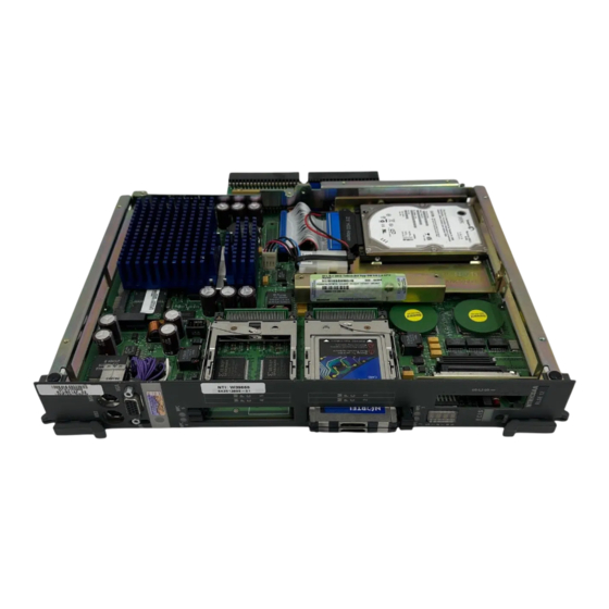
- Page 125 October 2006 Performing hardware maintenance and mechanical assembly 201i server component diagram: exploded view The following diagram identifies component locations on the 201i server. MPC-8 cards DRAM Secondary backplane connector Disk drive Power mounting cable bracket assembly assembly Secondary backplane...
- Page 126 Performing hardware maintenance and mechanical assembly Standard 1.05 201i server component diagram: complete assembly The following diagram shows the 201i server when it is completely assembled. G101544 CallPilot...
- Page 127 Heat sink Hard drive power cable Hard drive data cable Secondary backplane connector pin Secondary backplane connector 3.5" IDE hard drive Hard drive mounting bracket Software feature key (dongle) Faceplate Monitor connector Mouse connector Keyboard connector 201i Server Maintenance and Diagnostics...
-
Page 128: Replacing The Ide Hard Drive
The following equipment is required for this procedure: antistatic wrist strap Phillips No. 1 screwdriver Before you begin Before you replace the hard drive, review the following: “Removing the server from the switch,” on page 121 the “201i server component diagram: exploded view,” on page 125 CallPilot... -
Page 129: To Remove The Ide Hard Drive
Hard drive power cable and connectors Hard drive data cable and connectors Hard drive G101433 To remove the IDE hard drive 1 Do the following: a. Remove the two screws on the back of the motherboard. 201i Server Maintenance and Diagnostics... - Page 130 Performing hardware maintenance and mechanical assembly Standard 1.05 b. Remove the screw on the stiffening cage. c. Remove the two screws on the hard drive stiffener cage (along the backplane edge of the server). See the following diagram. Back of motherboard G101446 CallPilot...
- Page 131 Dislodge the power cable from its connector and lift it away from the motherboard. b. Slide one hand as far as you can beneath the hard drive so that it is securely supported and you can touch the data cable connector on the motherboard. G101447 201i Server Maintenance and Diagnostics...
- Page 132 5 Do the following: IF you are THEN replacing the hard drive continue with step 6. with a new one keeping the hard drive but continue with “To install the hard drive,” replacing the 201i server on page 133. CallPilot...
-
Page 133: To Install The Hard Drive
1 If you are replacing the hard drive with a new one, do the following: a. Attach the hard drive bracket to the new hard drive. b. Attach the power and data cables to the new hard drive. 201i Server Maintenance and Diagnostics... - Page 134 Performing hardware maintenance and mechanical assembly Standard 1.05 2 Connect the power and data cables to the 201i server motherboard. “Hard drive assembly diagram,” on page 129 Refer to CAUTION Risk of equipment damage Ensure the pins on the data connector on the motherboard line up correctly with the data cable connector.
-
Page 135: To Replace The Software Feature Key
Introduction The software feature key (dongle) stores the unique serial number of the server. If the 201i server must be replaced, use this procedure to move the software feature key from the faulty server to the replacement server. Equipment required... - Page 136 Performing hardware maintenance and mechanical assembly Standard 1.05 3 Insert the software feature key into the socket on the replacement server, lip side up. When the software feature key (dongle) is correctly installed, it is firmly seated in its socket. See the following diagram. Software feature key fully seated G101539...
-
Page 137: Replacing Multimedia Processing Cards
Introduction The Nortel MPC-8 card supports multimedia telephony services on the 201i server. Note: The 201i server motherboard contains one built-in MPC. This MPC is known as MPC 1. Supported MPC-8 card versions The 201i server supports MPC-8 cards, Release 14 or later. - Page 138 Four specially designed card slots for the MPC-8 are located on the 201i server faceplate. The MPC-8 card is keyed so that it fits only one way into the slot on the 201i server faceplate. If the card is inserted incorrectly, the card does not go all the way into the slot.
-
Page 139: To Remove An Mpc
CallPilot Manager software (as described in this procedure) before you remove it from the server. ATTENTION This procedure assumes that the 201i server is locked into position on the IPE shelf. If it is not, perform steps 3 and 4 only. - Page 140 Performing hardware maintenance and mechanical assembly Standard 1.05 2 Ensure that the MPC's LED on the 201i server faceplate is not lit, which indicates that the MPC is no longer receiving power and can be removed safely. CAUTION Risk of equipment damage If you remove an MPC while it is receiving power, this can damage the MPC or the 201i server.
-
Page 141: To Install An Mpc-8 Card
Performing hardware maintenance and mechanical assembly To install an MPC-8 card 1 Ensure that the MPC-8 card label is facing one of the following ways: facing to the right if the 201i server is inserted into the IPE shelf (see the following diagram) G101541... - Page 142 Performing hardware maintenance and mechanical assembly Standard 1.05 4 Run the Configuration Wizard to detect and initialize the new hardware. For instructions on running the Configuration Wizard, refer to the CallPilot <switch model> and CallPilot Server Configuration guide for your switch and server. Note: You do not need to change any data in the Configuration Wizard.
-
Page 143: Index
Multimedia Monitor, using diagnostics, running CallPilot services, Channel Monitor tab disabling Channel Monitor tab – working with CallPilot services CallPilot critical software, reinstalling DS30X links pane in DSP pane in – Channel Monitor, using channels 201i Server Maintenance and Diagnostics... - Page 144 CallPilot Manager maintenance Diagnostics section, Maintenance page activities diagnostics tool dependencies CallPilot diagnostics that can be run diagrams diagnostics-eligible 201i server replacing HEX display, location – start, about LEDs, location – starting display, HEX – states codes...
- Page 145 LEDs network LED IDE drive – noncritical OS and switch diagnostics location on 201i server MPC slot 201i Server Maintenance and Diagnostics...
- Page 146 TCP/IP diagnostics ipconfig nbtstat SCSI device LED netstat security event log ping description tracert server, 201i tracert command startup failure parameters and descriptions 8051, what to do running from the operating system CallPilot, what to do syntax Session Trace utility...
- Page 147 October 2006 Index utilities Diagnostics Tool PEP Maintenance Session Trace System Monitor WARN (fault status), what to do 201i Server Maintenance and Diagnostics...
- Page 148 Index Standard 1.05 CallPilot...
- Page 150 The information in this document is proprietary to Nortel Networks. *Nortel Networks, the Nortel Networks logo, and the Globemark are trademarks of Nortel Networks. *Microsoft, MS, MS-DOS, Windows, and Windows NT are registered trademarks of Microsoft Corporation.
Need help?
Do you have a question about the 201i and is the answer not in the manual?
Questions and answers