
Subscribe to Our Youtube Channel
Related Manuals for IBA ibaPADU-8AI-U


Summary of Contents for IBA ibaPADU-8AI-U
- Page 1 Manual ibaPADU-8AI-U/-8AI-I Parallel-Analog-Digital-Converter for 8 channels Manual Issue 1.6 Issue 1.6...
- Page 2 However, the information in this publication is updated regularly. Required cor- rections are contained in the following regulations or can be downloaded on the Internet. The current version is available for download on our web site http://www.iba-ag.com. Protection note Windows®...
-
Page 3: Table Of Contents
Manual Table of contents About this manual ................... 5 Target group ....................5 Notations ....................... 5 Used symbols....................6 Introduction ..................... 7 Scope of delivery..................... 9 Safety instructions ..................9 Designated use ..................... 9 Special advices ..................... 9 System requirements ..................10 Hardware .................... - Page 4 Manual ibaPADU-8AI-U/-8AI-I 9.1.3 Padu 8/-I – “Analog“ tab ................25 9.1.4 Padu 8 – „Digital“ tab .................. 26 Technical Data ....................27 10.1 Main data ....................27 10.2 Dimension sheet ..................30 10.3 Example for FO budget calculation ............. 31 Support and contact ..................
-
Page 5: About This Manual
Manual About this manual This manual describes the construction, the use and the operation of the devices ibaPADU-8AI-U and ibaPADU-8AI-I. Target group This manual addresses in particular the qualified professionals who are familiar with han- dling electrical and electronic modules as well as communication and measurement tech- nology. -
Page 6: Used Symbols
Manual ibaPADU-8AI-U/-8AI-I Used symbols If safety instructions or other notes are used in this manual, they mean: The non-observance of this safety information may result in an imminent risk of death or severe injury: By an electric shock! Due to the improper handling of software products which are coupled to... -
Page 7: Introduction
The ibaPADU (Parallel Analog Digital Unit) device family is designed for data acquisition of analog and digital signals. The new models ibaPADU-8AI-U and ibaPADU-8AI-I pro- vide 8 digital inputs and 8 analog voltage or current inputs and replace previous devices. - Page 8 In brief: Replacement for the previous ibaPADU-8 devices ibaPADU-8AI-U 8 digital inputs and 8 analog voltage inputs Input level ±10 V, ±24 V or ±60 V Input impedance 100 kΩ or 1 MΩ (selectable) ...
-
Page 9: Scope Of Delivery
The device is electrical equipment. It may be used only in the following applications: Automation of industrial systems Measurement data logging and analysis Applications of iba software products (ibaPDA, ibaLogic etc.) The device is only to be applied as shown in the Technical Data chapter. Special advices... -
Page 10: System Requirements
1 free PCI/PCIe slot 512 MB RAM 4 GB free memory on the hard drive for measurement values On the iba website http://www.iba-ag.com, you find suitable industry-type and desktop-type PC systems. One of the following cards in the PC: ... -
Page 11: Mounting And Dismounting
Manual Mounting and dismounting Mounting 1. Locate the DIN rail mounting clip on the rear side of the device. Slowly push down and in so that the bottom part of the mounting clips snaps onto the bottom part of the rail and firmly fixes the device to the DIN rail. -
Page 12: Device Description
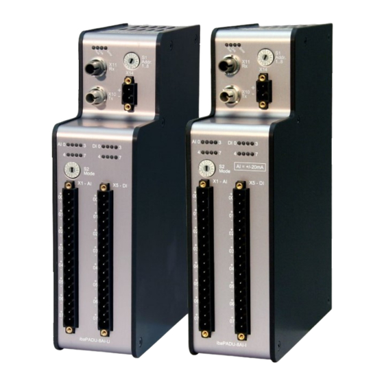
Manual ibaPADU-8AI-U/-8AI-I Device description Device view 7.1.1 Front view Operating state display Rotary switch S1 FO input (RX) X11 Power supply terminal X14 FO output (TX) X10 Status LEDs of analog channels Status LEDs of digital channels Rotary switch S2... -
Page 13: Indicating Elements
Error (red) Blinking Software error or Rotary switch S1 is set to an invalid address (0, 9…F) Hardware error Status of analog inputs of ibaPADU-8AI-U LED per Status/meaning Description (approx. values) channel Input range Input range Input range ±10 V... -
Page 14: Connections
The device requires an external DC 24 V ±10% power supply (unregulated). The oper- ating voltage should be run through the provided 2-pin Phoenix threaded coupling con- nector. If desired, you can order DIN rails or plug-in power supply units from iba. 7.3.3... - Page 15 Manual ibaPADU-8AI-U ibaPADU-8AI-I Pin assignment X1 Pin... Connection X5 Pin... Connection Analog input 00 + Digital input 00 + Analog input 00 − Digital input 00 − Analog input 01 + Digital input 01 + Analog input 01 −...
-
Page 16: Grounding Screw X29
The Ethernet interface is set as default to the IP address 192.168.1.1. Note Please contact iba regarding loading new firmware. You will get the required files and further information. Important note In normal operation mode the Ethernet cable must not be connected. - Page 17 The file "Event.log" is always present by default and contains various device infor- mation, such as the current firmware version. 5. Rename the update file “padu*_v*.iba” to “padu*_v*.iba.ready” and copy it via the FTP connection to the directory on the device.
-
Page 18: Rj11 Connection X9
Manual ibaPADU-8AI-U/-8AI-I 7.3.6 RJ11 connection X9 A notebook equipped with an ibaCom-PCMCIA-F card can be connected at the RJ11 jack at the bottom of the device. Thus, it is possible to carry out measurements in parallel at the RJ11 jack without affect- ing the data transmission on the fiber optic cable. - Page 19 Manual Filter type Order Cutoff frequency R/C low-pass (1) 4 kHz Antialiasing digital (2) 330 Hz Butterworth, digital (3) 250 Hz Note The 330 Hz cutoff frequency of the digital Antialiasing filter is optimized for the sampling rate 1 ms.
-
Page 20: System Integration
Manual ibaPADU-8AI-U/-8AI-I System integration Homogeneous ibaPADU-8AI chain Up to 8 devices can be connected in a line topology. The outputs of the devices are to be connected with the input of the following devices until all devices are interconnected and the last device is connected to the ibaFOB card. All addresses (1...8) within a chain must be unique. -
Page 21: Ring Topology With Ibalogic-V3 (Asynchronous Mode)
Manual Ring topology with ibaLogic-V3 (Asynchronous mode) When used as replacement for previous devices ibaPADU-8AI supports also the function described here. The sampling rate may be changed for the devices within one ring to- pology between 1.0 ms and 9.9 ms in steps of 100 µs. This function can only be used with ibaLogic-V3 and with older ibaFOB cards (except ibaFOB-D). -
Page 22: Configuration
Manual ibaPADU-8AI-U/-8AI-I Configuration The description of the device configuration is based on ibaPDA. Configuration in ibaPDA Set the desired device mode with the rotary switch S2 before initial operation, see also chapter 7.4.2 “Rotary switch S2”. The familiar program interface of the previous devices is retained for ibaPADU-8AI. - Page 23 3. Alternatively you can add the device manually. Right-click on the link of the ibaFOB-D card the device should be connected to. Select “Add module…” and then: - “Padu 8” for ibaPADU-8AI-U - “Padu 8-I” for ibaPADU-8AI-I. The device will be listed in the signal tree.
-
Page 24: Padu 8/-I - „General" Tab
The high and low end of the input range is displayed here and may be adjusted if needed (e. g. ibaPADU-8AI-U with input level 24 V or 60 V). The input range de- pends on the type of analog inputs (voltage or current) and the adjusted device mode (see chapter 7.4.2). -
Page 25: Padu 8/-I - "Analog" Tab
Manual 9.1.3 Padu 8/-I – “Analog“ tab Figure 7: Padu 8 – „Analog“ tab Name Assign a meaningful name to each signal and you can enter additionally two com- ments when clicking on the symbol in the field “Name”. -
Page 26: Padu 8 - „Digital" Tab
Manual ibaPADU-8AI-U/-8AI-I 9.1.4 Padu 8 – „Digital“ tab Figure 8: Padu 8 – „Digital“ tab Name, Active, Actual, see “Analog” tab. Issue 1.6... -
Page 27: Technical Data
Manual Technical Data 10.1 Main data Short description Name ibaPADU-8AI-U ibaPADU-8AI-I Description Input module with 8 digital and 8 Input module with 8 digital analog voltage inputs voltage inputs and 8 analog current inputs Order no. 10.100000 10.100010 Analog inputs... - Page 28 Manual ibaPADU-8AI-U/-8AI-I Connector type 1 x 16-pin multi-pin connector; clamp-type terminal (0.2 mm to 2.5 mm ), screw connection, included in delivery ibaNet interface Number Design Fiber optic cable ibaNet protocol 3Mbit Data transmission rate 3.3 Mbit/s Sampling rate 1 kHz...
- Page 29 47 CFR § 2.1077 Compliance Information Unique Identifier: 10.100000 ibaPADU-8AI-U 10.100010 ibaPADU-8AI-I Responsible Party - U.S. Contact Information iba America, LLC 370 Winkler Drive, Suite C Alpharetta, Georgia 30004 (770) 886-2318-102 www.iba-america.com FCC Compliance Statement This device complies with Part 15 of the FCC Rules. Operation is subject to the following two conditions: (1) This device may not cause harmful interference, and (2) this device must ac- cept any interference received, including interference that may cause undesired operation.
-
Page 30: Dimension Sheet
Manual ibaPADU-8AI-U/-8AI-I 10.2 Dimension sheet (Dimensions given in mm) Figure 9: Dimension sheet (Dimensions given in mm) Figure 10: Dimension sheet with cables Issue 1.6... -
Page 31: Example For Fo Budget Calculation
Manual 10.3 Example for FO budget calculation As an example, an FO connection from an ibaFOB-io-Dexp card (FO transmitter) to an ibaBM-PN device (FO receiver) is used. Figure 11: Example: simple connection for FO budget calculation The example refers to a point-to-point connection with an FO cable of type 62.5/125 µm. - Page 32 Manual ibaPADU-8AI-U/-8AI-I Equation for calculating the FO budget (A Budget ���� = |(���� − ���� ������������������������ ���� ���������������� ���� �������� ���� �������������������� = sensitivity of FO receiving interface Receiver = output power of FO transmitting interface Sender Equation for calculating the fiber optic cable length (l ����...
-
Page 33: Support And Contact
Mailing address iba AG Postbox 1828 D-90708 Fuerth Germany Delivery address iba AG Gebhardtstrasse 10 D-90762 Fuerth Germany Regional and Worldwide For contact data of your regional iba office or representative please refer to our web site www.iba-ag.com. Issue 1.6...
Need help?
Do you have a question about the ibaPADU-8AI-U and is the answer not in the manual?
Questions and answers