
Subscribe to Our Youtube Channel
Related Manuals for Classic Auto Air Flex FIt Series

Summary of Contents for Classic Auto Air Flex FIt Series
- Page 1 Installation Manual Custom Colder The Climate Control System © DOCUMENT #1-1090 ©2016 ClassicAutoAir / 07.16 ©...
- Page 3 Before starting, read the instructions carefully, from beginning to end, and follow the proper sequence. On the next page you’ll find a safety and general checklist that you should read before starting your installation. Again, thank you from our entire staff. CLASSIC AUTO AIR Page 1...
- Page 4 Should you have any technical questions, or feel you have defective components (or missing items), call us immediately, we will be glad to assist you. Our toll-free number is listed on every page, we’re here to help! YOU CAN NOW BEGIN THE INSTALLATION... CLASSIC AUTO AIR Page 2...
- Page 5 As the liquid refrigerant goes through the expansion valve it rapidly cools in the evaporator. A fan blows over the evaporator and cools the air that blows out your vents CLASSIC AUTO AIR Page 3...
- Page 6 Three 1/4 - #20 x 1" Bolts will be located in unit box. and Washers Four #10 - 16 x 3/4" Tek Screws Refrigerant Tape Electronic Water Control Valve Clear Plastic Drain Tube Six Worm Gear Clamps CLASSIC AUTO AIR Page 4...
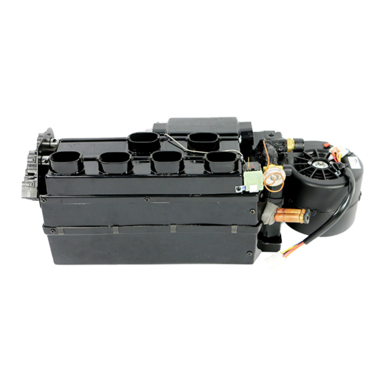
- Page 7 Expansion Valve Liquid Pressure Line Suction Line Defrost Hose Connections Mounting Brakets Floor Hose Connection Suction Line Actuator Motors Blower Motor Blower Motor Dash Hose Connections Thermostat Expansion Valve Heater Hose Connections Liquid Pressure Line CLASSIC AUTO AIR Page 5...
- Page 8 Harness System The ECU will be attached for shipping purposes to the body of the main unit. You will need to detach and mount Two #10 - 16 x 3/4" Tek Screws near your evaporator unit. CLASSIC AUTO AIR Page 6...
- Page 9 Wiring Harness - Power Supply Blower Switch Plug Connection Cable Integrators Relay Four #10 - 16 x 3/4" Tek Screws Blower Switch Knob Two - Cable Clips Blower Switch NOTE: Illustrations NOT shown actual size CLASSIC AUTO AIR Page 7...
- Page 10 Rotary Wiring Harness - Power Supply Blower Switch Plug Connection Cable Integrators Relay Four #10 - 16 x 3/4" Tek Screws Two - Cable Clips Rotary Blower Switch Rotary Blower Switch Knob NOTE: Illustrations NOT shown actual size CLASSIC AUTO AIR Page 8...
- Page 11 (engine compartment) Ground Ground Ground Thermostat OEM Power Supply Billet Controls Wiring Harness - Power Supply Blower Switch Plug Connection Relay Four #10 - 16 x 3/4" Tek Screws NOTE: Illustrations NOT shown actual size CLASSIC AUTO AIR Page 9...
- Page 12 The most important aspect is that your OEM levers, which ever two you choose to use, move their entire possible distance of travel (when viewed from the front of the control head). CLASSIC AUTO AIR Page 10...
- Page 13 Bench Calibration Steps 1 Click! Connect Yellow Harness into Defrost/Heat Servo Motor Connect Blue Harness into Dash Servo Motor CLASSIC AUTO AIR Page 11...
- Page 14 OEM fuse box. The wiring harneses are color coded, just follow the connections as Connect Yellow Harness into Face / Floor Port on ECU specified. CLASSIC AUTO AIR Page 12...
- Page 15 Connect both BLUE leads into thermostat Connect ground. (either lead into either terminal) 12V Power (20 amp fuse) Grd - Grd - Grd - (Single white lead is to be connected to the pressure switch on the drier) CLASSIC AUTO AIR Page 13...
- Page 16 ATTENTION THE FOLLOWING BENCH CALIBRATION & OPERATION PAGES ARE FOR BILLET AND SPECIALTY CONTROLS. IF YOU PURCHASED A EZ CABLE INTEGRATOR SET UP PLEASE SKIP TO PAGES 18-22. CLASSIC AUTO AIR Page 14...
- Page 17 • Calibration, Steps 1 thru 3 Start by positioning the knobs as shown: Insert Calibration Key as shown (LED side up) into 6-pin Fan: Off connection in ECU Mode: Floor Temp: Cold YOU WILL SEE... Move Fan Knob to High... CLASSIC AUTO AIR Page 15...
- Page 18 • Calibration, Steps 4 and 5 AFTER YOU MOVE THE KNOB YOU WILL SEE... Move MODE knob to DASH in one motion AFTER YOU MOVE THE KNOB YOU WILL SEE... Move TEMP knob to HOT in one motion CLASSIC AUTO AIR Page 16...
- Page 19 You will be able to hear the internal door(s) move back and forth and feel air coming out of the outlets REMOVE CALIBRATION KEY FROM ECU AND STORE IN A SAFE PLACE Move FAN knob to OFF CLASSIC AUTO AIR Page 17...
- Page 20 • Function Test, Steps 1 thru 3 Move FAN knob to HIGH Move MODE knob to DEFROST Move MODE knob to FLOOR Move MODE knob to DASH AIR OUT OF DEFROST VENTS AIR OUT OF DASH VENTS AIR OUT OF FLOOR CLASSIC AUTO AIR Page 18...
- Page 21 GET THE CORRECT OUTCOME, PLEASE CALL TECH SUPPORT BEFORE OPEN CLOSED INSTALLING INTO VEHICLE. You will be able to see through water valve passage You will NOT be able to see through water valve passage CLASSIC AUTO AIR Page 19...
- Page 22 ATTENTION THE FOLLOWING BENCH CALIBRATION & OPERATION ONLY. IS FOR CABLE INTAGRATORS CLASSIC AUTO AIR Page 20...
- Page 23 Start by positioning the knobs as shown: Insert Calibration Key as shown (LED side up) into 6-pin Fan: Off connection in ECU Mode: Floor Temp: Cold HIGH DASH COLD YOU WILL SEE... Move Fan Lever to High... CLASSIC AUTO AIR Page 21...
- Page 24 • Calibration, Steps 4 and 5 AFTER YOU MOVE THE KNOB YOU WILL SEE... Move MODE arm to DASH in one motion AFTER YOU MOVE THE KNOB YOU WILL SEE... Move TEMP arm to HOT in one motion CLASSIC AUTO AIR Page 22...
- Page 25 You will be able to hear the internal door(s) move back and forth and feel air coming out of the outlets HIGH DASH COLD REMOVE CALIBRATION KEY FROM ECU AND STORE IN A SAFE PLACE Move FAN lever to OFF CLASSIC AUTO AIR Page 23...
- Page 26 Move MODE arm to DEFROST Move MODE arm to FLOOR/DEFROST Move FAN lever to HIGH Move MODE arm to DASH AIR OUT OF DEFROST VENTS AIR OUT OF DASH VENTS AIR OUT OF FLOOR/DEFROST VENTS CLASSIC AUTO AIR Page 24...
- Page 27 GET THE CORRECT OUTCOME, PLEASE CALL TECH SUPPORT BEFORE INSTALLING INTO VEHICLE. OPEN CLOSED You will be able to see through water valve passage You will NOT be able to see through water valve passage CLASSIC AUTO AIR Page 25...
- Page 28 Beware any hoses or hardlines on the engine bay side of your fire wall. Locate a mounting place for the ECU in a location.. DASH EVAP UNIT LEVEL Be sure to align the evaporator unit level with the bottom of instrument panel as shown above. CLASSIC AUTO AIR Page 26...
- Page 29 When installing your bulkhead plate make sure to use of mineral oil in each connection. the supplie backup plate as shown above. CLASSIC AUTO AIR Page 27...
- Page 30 When drilling make sure to check for obstructions on either side of the rewall. We recommend using grommets if a bulkhead plate is not utilized. Route the hoses thru the re wall into the engine bay. CLASSIC AUTO AIR Page 28...
- Page 31 Exploded View of Typical Installation Four 1/4 - #20 x 1" bolts and washers 5/16” Holes Drilled Thru Firewall Use grommets or optional bulkhead adaptors CLASSIC AUTO AIR Page 29...
- Page 32 Feed drain tube thru the hole drilled earlier. CLASSIC AUTO AIR Page 30...
- Page 33 Connect the remaining outlet on water valve labeled water pump to the water pump using 5/8” dia. heater hose with the supplied worm gear clamp. FOLLOW THESE TAGS... CHECK IT TWICE BEFORE PROCEEDING! CLASSIC AUTO AIR Page 31...
- Page 34 THESE ARE THE PARTS YOU WILL FIND IN BAG KIT D You will these parts and hardware during the next series of installation steps. One Duct Hose, 2" I.D., 15’ Long Two Remote Heat Dump Four #10 - 16 x 3/4" Tek Screws Six Zip-Ties CLASSIC AUTO AIR Page 32...
- Page 35 THESE ARE THE PARTS YOU WILL FIND IN BAG KIT E You will these parts and hardware during the next series of installation steps. Your choice of vents and defrost vents will located with Bag Kit E CLASSIC AUTO AIR Page 33...
- Page 36 1) When routing the hose the less bend on the hose teh easier air will ow. 2) Do not kinck the hose. 3) Test t before nal instaltion. 4) Use zip ties to fasen the hose to any adaptor/ vent. CLASSIC AUTO AIR Page 34...
- Page 37 C: Some vents can be inserted into OEM vents holes, or you may need to cut-out holes within the dash... measure twice - cut once. D: Use zip-ties to connect the flex hoses to the back of the vents. CLASSIC AUTO AIR Page 35...
- Page 38 As the name implies mount to the bottom of your dash with a pair of screws. You will also have the choise of indash vents witch will require measuring and cutting into your dash. CLASSIC AUTO AIR Page 36...
- Page 39 CENTER VENTS INSTALLATION Dash Hose Connections Dash Hose Connections CLASSIC AUTO AIR Page 37...
- Page 40 Two #6 FIO 45º One #10 FIO 45º One #10 FIO 90º Service Port Drier Drier Bracket PN# 12-1008 PN# 19-1003 One #6 FIO Straight Three Refrigerant Hoses One #8 FIO Straight One #10 FIO Straight CLASSIC AUTO AIR Page 38...
- Page 41 (see figure 37). Be sure to retain all the mounting screws – you’ll reinstall these pieces in the exact reverse order with the OEM screws. *If Applicable. CLASSIC AUTO AIR Page 39...
- Page 42 Remove dust cover and attach wiring harness to electrical connections. TOP VIEW OF DRIER #10-20 x 1/4” HEX-HEAD #10 - 16 X 3/4” TEK SCREWS Be sure to mount drier vertically with fittings to top. CLASSIC AUTO AIR Page 40...
- Page 43 (MAKE CERTAIN LARGE FITTING CONNECTION IS TO THE TOP. FAILURE TO DO SO WILL CAUSE SYSTEM TO FUNCTION INCORRECTLY) #10-20 x 1/4” HEX-HEAD #10 - 16 X 3/4” TEK SCREWS LARGE CONNECTION SMALL CONNECTION CLASSIC AUTO AIR Page 41...
- Page 44 PASSENGER SIDE COMPRESSOR HOSE ROUTING A: #6 Liquid Hose ( ⁄ ”) B: #8 Dischage Hose ( ⁄ ”) C: #10 Suction Hose (½”) Reminder... Use two wrenches to tighten o-ring fittings CLASSIC AUTO AIR Page 42...
- Page 45 DRIVER SIDE COMPRESSOR HOSE ROUTING A: #6 Liquid Hose ( ⁄ ”) B: #8 Dischage Hose ( ⁄ ”) C: #10 Suction Hose (½”) Reminder... Use two wrenches to tighten o-ring fittings CLASSIC AUTO AIR Page 43...
- Page 46 Re-intall any componets that had to be removed during the instalation such as hood latch or grill. CLASSIC AUTO AIR Page 44...
- Page 47 1. HIGH-SIDE PRESSURES (150-275 PSI) the engine with the clutch engaged. 2. LOW-SIDE PRESSURES (10-25 PSI in a steady state) Readings above are based on an ambient temperature of 90˚ with an adequate airflow on condenser CLASSIC AUTO AIR Page 45...
-
Page 48: Troubleshooting Guide
WATER FLOW IS WITH THE DIRECTION OF THE ARROW. As the engine heats up that water performed by a local shop and can help determine the extent of the systems problem. transfers the heat to the coil, thus overpowering the a/c coil. A leaking or faulty valve will CLASSIC AUTO AIR Page 46... - Page 49 Trouble Shooting Your Classic Auto Air A/C System PROBLEM: system is not cooling properly If the paper is held in place you are at least getting some air flow. If the high side decreases during test 2 & 3 then your condenser is not getting enough air which is ISSUE: cold at idle, warmer when raising engine RPM’s...
Need help?
Do you have a question about the Flex FIt Series and is the answer not in the manual?
Questions and answers