Table of Contents
Advertisement
Quick Links
Advertisement
Table of Contents

Subscribe to Our Youtube Channel
Related Manuals for Rohde & Schwarz ENV432


Summary of Contents for Rohde & Schwarz ENV432
- Page 1 R&S ENV432 ® Four-Line V-Network User Manual 1326.6492.04 – 03...
- Page 2 Printed in Germany – Subject to change – Data without tolerance limits is not binding. ® R& S is a trademark of Rohde & Schwarz GmbH & Co. KG. Trade names are trademarks of the owners. The following abbreviations are used in this manual: ® R& S ENV432 is abbreviated as R&S ENV432...
- Page 3 Basic Safety Instructions Always read through and comply with the following safety instructions! All plants and locations of the Rohde & Schwarz group of companies make every effort to keep the safety standards of our products up to date and to offer our customers the highest possible degree of safety. Our products and the auxiliary equipment they require are designed, built and tested in accordance with the safety standards that apply in each case.
- Page 4 Basic Safety Instructions Symbol Meaning Symbol Meaning Caution ! Hot surface Alternating current (AC) Protective conductor terminal Direct/alternating current (DC/AC) To identify any terminal which is intended for connection to an external conductor for protection against electric shock in case of a fault, or the terminal of a protective earth Earth (Ground) Class II Equipment...
- Page 5 Basic Safety Instructions Operating states and operating positions The product may be operated only under the operating conditions and in the positions specified by the manufacturer, without the product's ventilation being obstructed. If the manufacturer's specifications are not observed, this can result in electric shock, fire and/or serious personal injury or death. Applicable local or national safety regulations and rules for the prevention of accidents must be observed in all work performed.
- Page 6 Basic Safety Instructions 6. The product may be operated only from TN/TT supply networks fuse-protected with max. 16 A (higher fuse only after consulting with the Rohde & Schwarz group of companies). 7. Do not insert the plug into sockets that are dusty or dirty. Insert the plug firmly and all the way into the socket provided for this purpose.
- Page 7 Basic Safety Instructions 2. Before you move or transport the product, read and observe the section titled "Transport". 3. As with all industrially manufactured goods, the use of substances that induce an allergic reaction (allergens) such as nickel cannot be generally excluded. If you develop an allergic reaction (such as a skin rash, frequent sneezing, red eyes or respiratory difficulties) when using a Rohde &...
- Page 8 Basic Safety Instructions 2. Adjustments, replacement of parts, maintenance and repair may be performed only by electrical experts authorized by Rohde & Schwarz. Only original parts may be used for replacing parts relevant to safety (e.g. power switches, power transformers, fuses). A safety test must always be performed after parts relevant to safety have been replaced (visual inspection, protective conductor test, insulation resistance measurement, leakage current measurement, functional test).
- Page 9 Basic Safety Instructions 3. If you use the product in a vehicle, it is the sole responsibility of the driver to drive the vehicle safely and properly. The manufacturer assumes no responsibility for accidents or collisions. Never use the product in a moving vehicle if doing so could distract the driver of the vehicle. Adequately secure the product in the vehicle to prevent injuries or other damage in the event of an accident.
- Page 10 Instrucciones de seguridad elementales Instrucciones de seguridad elementales ¡Es imprescindible leer y cumplir las siguientes instrucciones e informaciones de seguridad! El principio del grupo de empresas Rohde & Schwarz consiste en tener nuestros productos siempre al día con los estándares de seguridad y de ofrecer a nuestros clientes el máximo grado de seguridad. Nuestros productos y todos los equipos adicionales son siempre fabricados y examinados según las normas de seguridad vigentes.
- Page 11 Instrucciones de seguridad elementales Señalización de seguridad de los productos Las siguientes señales de seguridad se utilizan en los productos para advertir sobre riesgos y peligros. Símbolo Significado Símbolo Significado Aviso: punto de peligro general Tensión de alimentación de PUESTA EN MARCHA / PARADA Observar la documentación del producto Atención en el manejo de dispositivos de peso...
- Page 12 Instrucciones de seguridad elementales Palabras de señal y su significado En la documentación del producto se utilizan las siguientes palabras de señal con el fin de advertir contra riesgos y peligros. Indica una situación de peligro que, si no se evita, causa lesiones graves o incluso la muerte.
- Page 13 Instrucciones de seguridad elementales Seguridad eléctrica Si no se siguen (o se siguen de modo insuficiente) las indicaciones del fabricante en cuanto a seguridad eléctrica, pueden producirse choques eléctricos, incendios y/o lesiones graves con posible consecuencia de muerte. 1. Antes de la puesta en marcha del producto se deberá comprobar siempre que la tensión preseleccionada en el producto coincida con la de la red de alimentación eléctrica.
- Page 14 Instrucciones de seguridad elementales 11. A menos que esté permitido expresamente, no retire nunca la tapa ni componentes de la carcasa mientras el producto esté en servicio. Esto pone a descubierto los cables y componentes eléctricos y puede causar lesiones, fuego o daños en el producto. 12.
- Page 15 Instrucciones de seguridad elementales 5. Ciertos productos, como p. ej. las instalaciones de radiocomunicación RF, pueden a causa de su función natural, emitir una radiación electromagnética aumentada. Deben tomarse todas las medidas necesarias para la protección de las mujeres embarazadas. También las personas con marcapasos pueden correr peligro a causa de la radiación electromagnética.
- Page 16 Instrucciones de seguridad elementales Baterías y acumuladores o celdas Si no se siguen (o se siguen de modo insuficiente) las indicaciones en cuanto a las baterías y acumuladores o celdas, pueden producirse explosiones, incendios y/o lesiones graves con posible consecuencia de muerte. El manejo de baterías y acumuladores con electrolitos alcalinos (p. ej. celdas de litio) debe seguir el estándar EN 62133.
- Page 17 Instrucciones de seguridad elementales Eliminación/protección del medio ambiente 1. Los dispositivos marcados contienen una batería o un acumulador que no se debe desechar con los residuos domésticos sin clasificar, sino que debe ser recogido por separado. La eliminación se debe efectuar exclusivamente a través de un punto de recogida apropiado o del servicio de atención al cliente de Rohde &...
- Page 18 이 기기는 가정용(B급) 전자파 적합기기로서 주로 가정에서 사용하는 것을 목적으로 하며, 모든 지역에서 사용할 수 있습니다...
- Page 19 Customer Support Technical support – where and when you need it For quick, expert help with any Rohde & Schwarz equipment, contact one of our Customer Support Centers. A team of highly qualified engineers provides telephone support and will work with you to find a solution to your query on any aspect of the operation, programming or applications of Rohde &...
-
Page 20: Table Of Contents
R&S ENV432 Contents Contents 1 Safety Instructions................5 2 Introduction ..................7 Front View ........................8 2.1.1 Artificial Hand ......................... 8 2.1.2 Ground Terminal ......................8 2.1.3 Schuko Socket (EUT 1) ....................9 2.1.4 CEE Socket (EUT 2) ...................... 9 2.1.5... - Page 21 R&S ENV432 Contents 5 Operating the V-Network ..............23 Measurement Example ....................23 6 Remote Control ................. 25 7 Maintenance and Upkeeping ............27 8 Calibration and Recommended Recalibration Interval ....28 9 Index ....................29 User Manual 1326.6492.04 - 03...
-
Page 22: Safety Instructions
(the R&S ENV432 only features a fuse in the auxiliary circuit of the ventilation system). Hence users must be protected against touching conductive parts that may carry live mains voltage. - Page 23 In general, when the R&S ENV432 is operated, make sure that the air supply is not obstructed from above or below. Since the device has air vents on the bottom side, it must be placed on a nonflammable base (e.g.
-
Page 24: Introduction
Deliver the unsymmetric disturbance voltage generated by the EUT to the test receiver in a defined manner ● Decouple the test circuit from mains disturbances The R&S ENV432 V-network is built with air-core inductances (50 μH and 250 μH) and conforms to the requirements specified in CISPR 16-1-2. Additional equipment: ●... -
Page 25: Front View
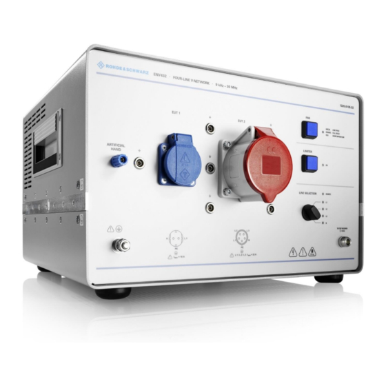
R&S ENV432 Introduction 2.1 Front View This figure shows the front view of the R&S ENV432. The individual elements are described in more detail in the subsequent sections. Fig. 1 Front View 1 = Artificial Hand 2 = Ground terminal... -
Page 26: Schuko Socket (Eut 1)
R&S ENV432 Introduction 2.1.3 Schuko Socket (EUT 1) Connector for disturbance voltage measurements on single-phase EUTs with an alternating voltage up to 240 V and direct voltages up to 350 V. When using this connector, the maximum constant current is 16 A. -
Page 27: Rear View
R&S ENV432 Introduction 2.2 Rear View This figure shows the rear view of the R&S ENV432. The individual elements are described in more detail in the subsequent sections. Fig. 2 Rear View 1 = Remote control input 2 = Ground terminal... -
Page 28: Protective Earth Conductor Terminal
2.2.5 Auxiliary Voltage Input Low-temperature connector with mains filters for applying the auxiliary voltage for powering fans and control logic. The R&S ENV432 can be set for two different nominal AC supply voltages: 115 V and 230 V. User Manual 1326.6492.04 - 03... -
Page 29: Block Diagram
R&S ENV432 Block Diagram 3 Block Diagram User Manual 1326.6492.04 - 03 E-12... -
Page 30: Preparing For Use
Be sure to observe the requirements in the safety instructions chapter as well as the section on protective earth grounding! In general, when the R&S ENV432 is operated, make sure that the air supply is not obstructed from above or below. Since the device has air vents on the bottom side, it must be placed on a nonflammable base (e.g. -
Page 31: Protective Earthing
) on the rear panel of the R&S ENV432. In this manner, the housing voltage will remain under 4 V even in case of a faulty EUT, i.e. in the event of a short circuit. -
Page 32: Ac Supply
Additional measures must be taken to protect the user against direct or indirect contact. V-networks such as the R&S ENV432 may also not contain any power fuses. Therefore, the connected mains supply must be sufficiently fused. If the EUT is operated on the single-phase SCHUKO socket outlet (EUT 1), the maximum permissible constant current is 16 A and the AC supply must thus be fused for 16 A. -
Page 33: Connecting The Rf Reference Ground
R&S ENV432 Preparing for Use Connecting the RF Reference Ground The V-network is connected via the power connector to the protective earth conductor (PE) of the mains supply; however, this is not suitable as an RF reference ground for measuring disturbance voltages. Therefore, the V-network must be connected to an appropriate RF reference ground to obtain reproducible and correct measurement results. -
Page 34: Avoiding Grounding Loops
R&S ENV432 Preparing for Use 4.5.1 Avoiding Grounding Loops To avoid grounding loops, the V-network should be grounded only once in the test setup, if possible. An example of using a protective earth choke (PE choke) was already given above (ensuring that the RF reference ground is not impacted by disturbance voltages from an industrial network). - Page 35 R&S ENV432 Preparing for Use Attenuation of sheath current choke measured in 150 Ω test setup Fig. 5 An attenuation of 20 dB means that the effective impedance of the sheath current choke is approx. 1500 . User Manual 1326.6492.04 - 03...
-
Page 36: Connecting The Auxiliary Voltage
V-network corresponds to the local AC supply voltage. The R&S ENV432 can be set for two different nominal AC supply voltages: 115 V and 230 V. In the 115 V setting, the nominal AC supply voltage range is 100 V to 120 V. In the 230 V setting, the nominal AC supply voltage range is 220 V to 240 V. -
Page 37: Connecting The Test Receiver
R&S ENV432 Preparing for Use Fig. 6 Low-temperature socket, fuse holder and line voltage selector After selection of the voltage range, connect the V-network to the supply voltage using the supplied power cable. If the V-network is correctly connected, one of the four green LEDs for displaying the test path should light up (depending on the position of the LINE SELECTION rotary switch). -
Page 38: Db Attenuator
R&S ENV432 Preparing for Use 4.8 10 dB Attenuator The built-in 10 dB attenuator attenuates the disturbance voltage emitted by the EUT by 10 dB. The attenuator ensures the 50 Ω termination required to meet the impedance tolerance, improves matching with the test receiver and provides a sufficiently high ohmic internal resistance to ensure correct functioning of the pulse limiter. -
Page 39: Connecting The Eut
RC combination. The RC combination is a series connection of a 220 pF capacitor C and a 510 Ω resistor R that is built into the R&S ENV432. It can be connected to the EUT via the 4 mm banana jack on the front (ARTIFICIAL HAND). -
Page 40: Operating The V-Network
V-network is fused correctly (see also chapter AC Supply). When the R&S ENV432 is operated, make sure that the air supply from above and below and from the side is not obstructed. The device may not be operated unsupervised and must be placed on a nonflammable base (e.g. - Page 41 R&S ENV432 Operating the V-Network Fig. 8 Measurement example (hand drill) Position Function Vertical RF reference ground, metal panel at least 2 m x 2 m AC supply cable Separate connecting line to artificial hand (ARTIFICIAL HAND) V-network Exposed metal collar...
-
Page 42: Remote Control
R&S ENV432 Remote Control 6 Remote Control The test path of the V-network to the test receiver can be selected manually using the rotary switch or via remote control. For remote control, connect the V-network to the test receiver with a connecting cable. - Page 43 EMI software, the operating menu for the ESH2-Z5 V-network also applies for control of the ENV432. For control of the R&S ENV432 with the R&S ESxI EMI test receivers (ESAI; ESBI; ESMI), the EZ-22 connecting cable is used. For control with other test receivers, the EZ-21 connecting cables (3 m or 10 m) are used.
-
Page 44: Maintenance And Upkeeping
R&S ENV432 Maintenance and Upkeeping 7 Maintenance and Upkeeping The device does not need any periodic maintenance. Maintenance is essentially restricted to cleaning the exterior of the device. Remove dirt from the housing with a damp cloth. Do not use aggressive cleaning agents. The device should be switched off during cleaning. -
Page 45: Calibration And Recommended Recalibration Interval
8 Calibration and Recommended Recalibration Interval The R&S ENV432 V-network was calibrated by the manufacturer after completion of production and was sent to the Rohde & Schwarz warehouse together with a calibration certificate. Since the V-network is neither electrically nor mechanically... -
Page 46: Index
R&S ENV432 Index 9 Index Attenuator ................ 21 Grounding loops .............. 17 Auxiliary Voltage .............. 19 Maintenance and upkeeping ..........27 Block diagram ..............12 Measurement example ............ 23 Calibration ............... 28 Protective earthing ............14 Calibration interval ............28 Pulse limiter ..............
Need help?
Do you have a question about the ENV432 and is the answer not in the manual?
Questions and answers