Table of Contents
Advertisement
Quick Links
PREFACE
MAESTRO EDGE 125 vehicle.
Thank you for selecting a
We wish you
Hero MotoCorp
many miles of continued riding pleasure in the years ahead.
We, at
, are committed to demonstrate excellence in our environment
Hero MotoCorp
performance on a continual basis, as an intrinsic element of our corporate philosophy. To
achieve this we commit ourselves to continue product innovations to improve environment
compatibility, comply with all applicable legislation including environment legislation and
strengthen the green supply chain.
Your vehicle is conforming to latest (Bharat stage-I norms) regulation for emission, safety &
V
noise levels. We are also using non asbestos brake shoes/pads and engine gaskets which are
environment friendly in nature.
This vehicle is fitted with a lighting feature known as "Automatic Headlamp ON". The feature
is mandated for all 2 Wheelers by Ministry of Road Transport & Highways (Government of
India) vide notification GSR 188 (E) dated 22nd February 2016. This feature helps in
conspicuity for improving rider safety. The headlamp of this vehicle will always be lit ON when
the engine gets ON.
This booklet is your guide to the basic operation and maintenance of your new
MAESTRO EDGE 125 vehicle.
Please take time to read it carefully. As
Hero MotoCorp
with any fine machine, proper care and maintenance is essential for trouble-free operation
and optimum performance.
Your Authorised
dealer will be glad to provide further information or
Hero MotoCorp
assistance and is equipped to handle your future service needs.
Let us make this world a safer, healthier and more environment friendly place.
Advertisement
Table of Contents

Related Manuals for HERO MAESTRO EDGE 125


Summary of Contents for HERO MAESTRO EDGE 125
- Page 1 PREFACE MAESTRO EDGE 125 vehicle. Thank you for selecting a We wish you Hero MotoCorp many miles of continued riding pleasure in the years ahead. We, at , are committed to demonstrate excellence in our environment Hero MotoCorp performance on a continual basis, as an intrinsic element of our corporate philosophy. To...
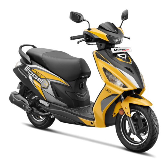
- Page 2 ACCESSORIES SHOWN MAY NOT BE THE PART OF STANDARD FITMENT. IT IS OUR ENDEAVOUR TO CONSTANTLY IMPROVE OUR PRODUCTS. THIS COULD LEAD TO CHANGE IN PRODUCT SPECIFICATIONS WITHOUT NOTICE. ‘MAESTRO EDGE 125’ COMPLIES WITH THE Hero MotoCorp Ltd LATEST EMISSION NORMS.
-
Page 3: Table Of Contents
Side stand/indicator/switch (Optional) REMOVING ROAD SALT • Pillion footrest STORAGE GUIDE • Women pillion step (Optional) BASIC TROUBLESHOOTING • BODY PARTS REMOVAL ROAD SIGNS Center compartment WARRANTY DETAILS • Body cover HERO GENUINE PARTS • Front center cover ZONAL/REGIONAL/AREA OFFICES •... -
Page 4: Vehicle Identification
JF17EH ##### Engine Year of Month of Assembly Plant Serial Number Description Manufacturing Manufacturing Model: MAESTRO EDGE 125 Engine Variant Disc/Cast wheel/Integrated brakes JFW10 JF17EH Drum/Cast wheel/Integrated brakes JFW07 JF17EH VIN and Engine number may be required: 1. During registration of the vehicle. -
Page 5: Vehicle Specification
VEHICLE SPECIFICATION ITEM SPECIFICATIONS Dimensions Overall length 1843 mm 718 mm Overall width Overall height 1188 mm Wheelbase 1261 mm Saddle height 775 mm Ground clearance (Under cover) 155 mm Weight Kerb weight 110 Kg Capacities Engine oil 0.80 litre at disassembly and 0.70 litre at draining 0.12 litre at disassembly Transmission oil 0.10 litre at draining... - Page 6 VEHICLE SPECIFICATION ITEM SPECIFICATIONS Front (Disc type) Dia 190 mm Front (Drum type) Internal expanding shoe type (Dia. 130 mm) Brakes Rear (Drum type) Internal expanding shoe type (Dia. 130 mm) (Integrated braking) Hydraulic brake fluid DoT 3 or DoT 4 Transmission Primary reduction Variomatic drive, (2.53-0.8)
-
Page 7: Vehicle Safety
Hero MotoCorp handles, and to become accustomed to the (page 7) vehicle. for more details. -
Page 8: Protective Apparel
If you are involved in a crash WARNING Personal safety is your first priority. If you or Not wearing a helmet increases the chance of • anyone else has been injured, take time to serious injury or death in a crash. assess the severity of the injuries and whether Be sure you and your pillion always wear a •... - Page 9 PROTECTIVE APPAREL Always wear HELMET Wear a face shield or goggles Wear bright or reflective clothing Wear gloves Shoes should be close fitting, low heels and offer ankle protection...
-
Page 10: Load Limits And Guidelines
However exceeding the weight limit or carrying an unbalanced load can seriously affect your vehicle's handling, braking and stability. Non accessories, Hero MotoCorp modifications, and poor maintenance can reduce your safety margin. The following pages give more specific information on loading, accessories and modifications. -
Page 11: Accessories And Modifications
We strongly recommend that you use only emission standards. genuine accessories that Hero MotoCorp have been specifically designed and tested for your vehicle. cannot test all Hero MotoCorp other accessories, you must be personally... -
Page 12: Safe Riding Tips
Take care of loose/hanging clothes while • solo/pillion riding. Get your vehicle serviced regularly by the • Authorised workshop. Hero MotoCorp Before riding make sure in which mode you • are riding whether with i3s switch “ON’ or “OFF”. -
Page 13: Tips For Healthy Environment
Hero MotoCorp incompatible spares and accessories can upset or deteriorate your vehicle’s running condition. Genuine engine oil: Hero 4T Plus SAE 10W 30 SL Grade (JASO MB) engine oil • recommended by and make sure you change it every 6000 km (with top Hero MotoCorp up every 3000 kilometres) to keep the engine fit and environment healthy. -
Page 14: Vehicle Views
VEHICLE VIEWS TOP VIEW 13 14 (1) Turn signal indicator (13) Tripmeter (2) Choke knob (14) Master cylinder (inside) (3) Horn switch (15) Front brake lever (4) Turn signal switch (16) Throttle grip (5) Integrated brake lever (17) i3s switch (6) Rear view mirror (18) Starter switch (7) Dimmer switch/Passing switch... - Page 15 LEFT SIDE VIEW (1) Brake disc (7) Pillion step (12) Rear grip (2) Caliper assembly (8) Kick starter pedal (13) Seat (3) CCB valve (inside) (9) Women pillion step (14) Boot lamp (inside) (optional) (4) Side stand switch (optional) (15) Rear luggage hook (10) Rear turn signal lamp (5) Side stand (optional) (16) Headlamp...
- Page 16 RIGHT SIDE VIEW (1) Exhaust muffler (5) Front turn signal lamp (8) USB charger (inside) (2) Oil level dipstick (6) Position lamp (9) Center compartment (inside) (3) Pillion step (7) Front luggage hook (10) Rear reflex reflector (4) Front inner box (optional) Accessories and features shown may not be part of standard fitment.
-
Page 17: Instruments And Indicators
PART FUNCTIONS INSTRUMENTS AND INDICATORS The indicators are in the speedometer panel above the headlamp. The functions are as below. Description Sl. No. Function Side stand indicator Light glows when the vehicle is parked on the side stand. High beam indicator Light glows when headlamp is in Hi beam. -
Page 18: Lcd Panel
(c) Service reminder The ervice reminder (1) is to indicate to an user to bring the vehicle to an Authorised workshop for service. Hero MotoCorp (1) Odometer (2) Tripmeter service reminder shall start blinking when (3) Reset button the vehicle covers kilometers as specified in the maintenance schedule. -
Page 19: Keys
KEYS This vehicle has two keys and a key number plate. (1) Service reminder (1) Keys (2) Key number plate TOTAL Indicator You will need the key number if you ever have DISTANCE to replace a key. Store the plate in a safe Behaviour (Odometer Reading) place. - Page 20 Replace the pads if worn out to the bottom movement to compensate pad wear. If the • of the groove. level decreases abruptly, check for leakage in the brake system and contact your Authorised Always replace both the pads as a set. • Hero MotoCorp workshop...
- Page 21 (1) Integrated brake lever (1) Wear indicator groove (3) Free play:10-20 mm Visit your Authorised • Hero MotoCorp Adjustment for the brake pad replacement. workshop Right hand front brake cable (A) on “1” side (c) Front brake system (Drum type) Push the integrated brake arm (4) by hand •...
- Page 22 (1) in the brake arm (2). (3) Adjusting nut (4) Brake joint pin Check the free play of integrated brake • If proper adjustment cannot be obtained by lever. this method, visit your Authorised Hero FREE PLAY: 10-20 mm MotoCorp workshop...
-
Page 23: Fuel
Other checks: Do not overfill the tank. There should be no fuel (4) in the filler neck (5). Check brake cable for kinks or signs of wear that could cause sticking or failure. Make sure the brake arm spring and fasteners are in good condition. - Page 24 When a problem resulting from the use of • petrol containing alcohol occurs, contact your Authorised workshop. Hero MotoCorp NOTE CAUTION If "Spark knock" or "pinking" occurs at a steady engine speed under normal load, When the fuel level indicator displays the last change petrol brand.
-
Page 25: Tyres (Tubeless)
TYRES (TUBELESS) leakage is often very slow, you should look closely for punctures whenever a tyre is not The tyres fitted on your vehicle are of fully inflated. TUBELESS type. Always check air pressure when your tyres are To safely operate your vehicle, the tyres "cold"-when the vehicle has been parked for must be of the proper type and size in good at least three hours. - Page 26 Repairing a puncture or removing a wheel requires special tools and technical expertise. If a tyre is punctured or damaged, it is advised to visit nearest tyre manufacture, Hero authorised dealer/workshop or the MotoCorp tyre repair shop who has expertise in...
- Page 27 If you decide to have a tyre replace be sure the For repair and replacement of tyre it is advised wheel is balanced before you ride. to visit your Authorised Hero MotoCorp Tyre replacement workshop. The tyres that were installed on your vehicle...
-
Page 28: Essential Individual Components
ESSENTIAL INDIVIDUAL COMPONENTS IGNITION SWITCH The ignition switch (1) is on the right side below the steering. “FUEL OPEN” Position “ON” ( ) Position “OFF” ( ) (1) Ignition switch Position/Lock Open (2) Ignition key (3) Steering lock position “SEAT OPEN” (4) Seat open Position (5) Fuel open... -
Page 29: Handlebar Switches Control
Right handlebar controls HANDLEBAR SWITCHES CONTROLS 1. Starter switch ( ) Left handlebar controls 1. Dimmer switch/Passing switch The starter switch (1) is next to the throttle grip. Press the switch upwards for high beam When the starter switch is pressed, the starter “... -
Page 30: Features
FEATURES NOTE (a) i3s (Idle stop start system) The engine will stall if the i3s switch is in • Starting & Warm up the engine: “ON” position during warm up. Keep the i3s switch (1) to “OFF” position. • Use choke during cold conditions. •... - Page 31 Driving with i3s switch in “ON” position: (b) Steering lock If the engine is stopped by i3s and its remain To lock the steering, turn the handlebar all the in “OFF” condition for more than 500 secs way to the left, turn the key (1) to "LOCK" then vehicle can only be started with brake &...
- Page 32 To access the holder or to secure a helmet to CAUTION the holder. Gently close the lid by hand. Sudden dropping Open the seat. • of the lid may result in breaking the lid lock and Attach/Hook the helmet strap or ring to the •...
- Page 33 (f) Center compartment The center compartment (1) is below the seat. For opening and closing the seat lock, see (page 29). MAXIMUM WEIGHT LIMIT: 10 Kg Never exceed the maximum weight limit, handling and stability may be severely affected. The center compartment may become heated by the engine.
-
Page 34: Center Compartment
Use of non-standard USB cable may cause damage to the mobile phones. Hero will not be responsible for damages MotoCorp caused due to use of non-standard USB cable. CAUTION Always place the device in a soft clean • cloth/towel to avoid any damage due to road shocks while riding. - Page 35 (j) Luggage hooks Two luggage hooks are provided in your vehicle to carry a light luggage like shopping bags or carry bags. Front luggage hook Front luggage hook (1) is provided below the handlebar. MAXIMUM WEIGHT LIMIT: 3.0 Kg (2) Rear luggage hook (k) Front inner box (Optional) The front inner box (1) is provided on the inner cover to carry some valuable items,...
-
Page 36: Side Stand/Indicator/Switch (Optional)
(1) should not glow. If the side stand indicator (1) does not • operate as described in above steps, please visit your Authorised Hero MotoCorp workshop. CAUTION Ensure that adequate care should be taken while cleaning the side stand switch. -
Page 37: Body Parts Removal
BODY PARTS REMOVAL (a) Center compartment Removal Open the seat (page 29). • Remove the bolts (1) from the center • compartment. (2) Right footrest (n) Women pillion step (Optional) This vehicle is equipped with women pillion step (1). (1) Bolts (1) Women pillon step Move the women pillion step to open. - Page 38 lamp connector (2) and USB charger connector (3). Remove the center compartment (4). • Installation Installation is in the reverse order of removal. NOTE Park the vehicle on its main stand when servicing the vehicle with the center compartment removed. (b) Body cover (2) Bolts Removal...
- Page 39 (5) Screws (7) Screws Remove the bolts (6). Remove the body cover bolts (8). • • (8) Body cover bolts (6) Bolts Remove the screws (7) from left and right Disconnect the fuel tank lid lock cable (9). • • side of the body cover.
- Page 40 (9) Fuel tank lid lock cable Pull the body cover slightly backwards and • release the tabs (11) from it slots (12) Remove the fuel filler cap (page 20). • from both sides of the vehicle. Disconnect the tail/stop lamp connector •...
-
Page 41: (14) Body Cover
(c) Front center cover Removal Remove the two screws (1) on the inner • cover side. (13) Drain tube Remove the complete body cover (14). • (1) Screws Remove the two screws (2) near the front • fender. (14) Body cover Installation Installation is in the reverse order of removal. - Page 42 Remove the four bolts (2) from the front • cover. Remove the top and bottom screws (3). • (3) Lugs Installation Installation is in the reverse order of removal. (d) Front cover (2) Bolts (3) Screws Removal Remove the screws (4) from the floor side •...
-
Page 43: Floor Side Cover
To dislodge the tabs (3), slide the floor side • covers to the rear side. (5) Front turn signal lamp connectors Installation (3) Tabs Installation is in the reverse order of removal. Remove the right floor side cover. • (e) Floor side cover Installation Right floor side cover Installation is in the reverse order of removal. - Page 44 To dislodge the tabs (3), slide the floor side • covers to the rear side. (1) Dust cover (2) Lock nut (3) Rear view mirror (3) Tabs Installation Remove the left floor side cover. Install the rear view mirror until it will •...
-
Page 45: Headlamp Focus Adjustment
(1) Screw (2) Headlamp case (3) Tabs (5) Headlamp connector (6) Position lamp connector Remove the screws (4). • Installation Pull the headlamp case (2) slightly up, • Installation is in the reverse order of removal. carefully release the tabs (3) from the slots. (g) Headlamp focus adjustment Vertical adjustment Headlamp focus is factory preset. -
Page 46: Pre-Ride Inspection
If you Fitting & fasteners-Check & tighten if detect any problem, be sure you take care of it • necessary. or have it corrected by your Authorised Hero Steering-Check for smooth action for easy workshop. • MotoCorp maneuverability. -
Page 47: Starting The Engine
Enter your name, address, and phone • NOTE number in this Owner's Manual and keep it During electric & throttle start, the engine will in your vehicle at all times. Many times turn off automatically, even though i3s switch stolen vehicles are identified by information is “ON”... - Page 48 Use kick starter: Make sure whether the i3s switch (2) is • • in “ON” or “OFF” position. With the throttle closed, operate the kick starter with a rapid and continuous motion. Continue warming up the engine until it • runs smoothly and responds to the throttle, when the choke knob is at “OFF”...
- Page 49 Make sure the throttle is closed and • the integrated brake is locked before moving the vehicle off the main stand. The rear wheel must be locked when moving the vehicle off the main stand or it may result in loss of control. Stand on the left side of the vehicle •...
- Page 50 Do not accelerate with the brakes applied, CLOSE this may lead to premature wear of brakes and transmission parts. To decelerate, close the throttle. • CLOSE OPEN (3) Throttle When slowing down the vehicle, • coordination of the throttle (3), front (4) and rear brake (5) is most important.
- Page 51 When approaching a corner or turn, After completing the turn, open the • • close the throttle (3) fully, and slow down throttle gradually to accelerate the the vehicle by applying both front (4) and vehicle. rear (5) brakes at the same time. CLOSE (3) Throttle (4) Front brake...
- Page 52 When descending a steep gradient, Avoid continuous use of the brakes, which • may result in overheating and reduction of close throttle (3) fully and by applying both braking efficiency. front (4) and rear (5) brakes at the same time. CLOSE (4) Front brake (3) Throttle...
-
Page 53: Parking
When riding on wet or loose surfaces, be • HOW TO USE MAIN STAND cautious. When riding in wet or rainy conditions or on loose surfaces, the ability to manoeuvre and stop will be reduced. For your safety: Exercise extreme caution when braking, •... -
Page 54: Tool Kit/First Aid Kit
Gauge (rolled bandage)-1 No. TOOL KIT/FIRST AID KIT • Sterilised elastic plaster-1 No. • The tool kit (1) is located in the center First aid bag-1 No. compartment (3). • CLEANING OF VEHICLE Some roadside repairs, minor adjustments and parts replacement can be performed with the Clean your vehicle regularly to protect the tools available in the kit. - Page 55 detergent and water. Rub the soiled area TEST BRAKES gently rinsing it frequently with fresh water. NOTE Take care to keep brake fluid or chemical • solvents off the vehicle. They will damage the plastic and painted surfaces. The inside of the headlamp lens may be •...
-
Page 56: Maintenance
Only you can decide the aintenance chedule. Consult your whether or not you should perform a given Authorised workshop for Hero MotoCorp task. recommendations applicable to your individual needs and use. WARNING If your vehicle overturns or is involved in a Failure to follow maintenance instructions •... -
Page 57: Safety Precautions
Remember that your Authorised Hero workshop knows your vehicle best MotoCorp and is fully equipped to maintain and repair it. To ensure best quality and reliability, it is recommended to use Hero MotoCorp genuine parts for repair and replacement. -
Page 58: Maintenance Schedule
Hero by properly trained and equipped technicians. Your Authorised workshop MotoCorp Hero MotoCorp meets all of these requirements. Ensure that each paid service is availed within 90 days or 3000 km from the date of previous service, whichever is earlier. - Page 59 MAINTENANCE SCHEDULE Dear Customer, We would strongly recommend the following schedule, to keep your vehicle in perfect running condition and healthy environment. vehicle subjected to severe use or ridden in dusty area will require more frequent servicing. WHICHEVER DURING FREE SERVICE PERIOD COMES FIRST AFTER FREE SERVICE ONCE IN EVERY...
- Page 60 WHICHEVER DURING FREE SERVICE PERIOD COMES FIRST AFTER FREE SERVICE ONCE IN EVERY SERVICE ITEMS Next Next Next Next 1st 60 DAYS 500- 3000- 6000- 9000- 12000- KM Note-1 3000 6000 9000 12000 15000 3500 6500 9500 12500 Front/Integrated Brake I, A I, A I, A...
-
Page 61: Air Cleaner Element
AIR CLEANER ELEMENT Refer to the safety precautions (page 54). The air cleaner element is of viscous type, it should be replaced at regular intervals (pages 55). Early replacement may be required when riding in unusually wet or dusty areas. Remove the body cover (page 35). - Page 62 Inspect the air cleaner element for any dust Clean the air cleaner housing (4) using a • • or dirt accumulation. shop towel. Replace the air cleaner element, if found • choked. (4) Air cleaner housing Install the air cleaner assembly (new, in case •...
-
Page 63: Air Cleaner Drain Tube Cleaning
AIR CLEANER DRAIN TUBE CLEANING Refer to the safety precautions (page 54). Remove the drain tube (1) from the air • cleaner assembly (2) and drain deposits in to a suitable container. Reinstall the drain tube. • (1) Screw (2) Tabs (3) Secondary air filter cover Remove the secondary air filter cover (3). -
Page 64: Throttle Operation
Install the removed parts in the reverse • order of removal. CAUTION Never use gasoline or low flash point solvents for cleaning the air cleaner element. A fire or explosion could result. THROTTLE OPERATION Cable inspection Check for smooth rotation of the throttle grip from the fully open to the fully closed position. -
Page 65: I3S Throttle Switch Adjustment
i3s THROTTLE SWITCH ADJUSTMENT While starting the vehicle with i3s switch “ON” condition and by rotating throttle grip inspect the following: (i) Start of the vehicle with more travel of throttle. (ii) Start of the vehicle within free play or no engine “OFF”... -
Page 66: Engine Oil
Stop the engine and wait for few seconds. ENGINE OIL • Remove the oil level dipstick, wipe it clean Use hero genuine engine oil or recommended • and reinsert the oil level dipstick without grade oil. screwing it in. - Page 67 (1) Drain bolt (3) Spring (4) Oil strainer screen (5) O-ring Install the oil strainer screen, spring and oil Remove the oil strainer screen cap (2). • • strainer screen cap. Install the drain plug. Fill crankcase with the recommended grade •...
-
Page 68: Final Drive Oil Replacement
It is suggested to get GRADE : SAE 10W 30 SL Grade it replaced by Authorised Hero MotoCorp At draining : 0.10 Litre workshop. At transmission disassembly: 0.12 Litre Park the vehicle on its main stand on a level •... - Page 69 SPARK PLUG Refer to the safety precautions (page 54). 0.8-0.9 mm Recommended spark plug. Champion-RG8YC (Federal Mogul) Remove the center cover (page 35). • Disconnect the noise suppressor cap (1) • from the spark plug. Clean any dirt around the spark plug base. •...
-
Page 70: Brake Shoe Wear
When the brake is applied, an arrow mark Park the vehicle on its main stand on a level • (1) on the brake arm (2) moves towards a surface. reference mark (3) on the brake panel (4). Switch “OFF” the i3s switch. •... -
Page 71: Battery
12V-4Ah, ETZ 5 MF Battery Battery charging It is not necessary to check the battery Always visit your Authorised Hero Moto electrolyte level or add distilled water as the workshop if you see any symptom of Corp battery is of Maintenance Free (sealed) battery discharge as earliest as possible to get type. -
Page 72: Fuse Replacement
(5) Battery (1) Battery band (2) Boot band clip Battery installation Disconnect the (-)ve terminal lead (3) from • the battery first, then disconnect the (+)ve Reinstall in the reverse order of removal. Be • terminal lead (4). sure to connect the (+)ve terminal first, then the (-)ve terminal. -
Page 73: Suspension
Leave the blown fuse in that circuit and have (A) & (B): Fuse holders your vehicle checked by your Authorised (1) Main fuse : 15A & 10A workshop. Hero MotoCorp (2) Spare fuse: 15A & 10A (3) Main fuse : 10A (4) Spare fuse: 10A SUSPENSION Inspection Check the front forks by locking the front •... -
Page 74: Bulb Replacement
vehicle is not parked on stand. The vehicle action should be smooth and there should be no oil leakage. BULB REPLACEMENT Refer to the safety precautions (page 54). The bulb becomes very hot while the lamp is “ON”, and remains hot for a while after it is turned “OFF”. - Page 75 Install a new bulb in the reverse order of • removal. (c) Tail/Stop lamp LED unit Remove the body cover (page 35). • Remove the fuel drain tube (1). • Remove the fuel tank lid lock cable from the • guide (2).
-
Page 76: Catalytic Converter
(1) Bulb holder (2) Rear turn signal bulb (3) Licence plate lamp bulb Install a new bulb in the reverse order of Install a new bulb in the reverse order of • • removal. removal. (e) Licence plate lamp bulb CATALYTIC CONVERTER Remove the body cover (page 35). -
Page 77: Air Suction Valve (Asv)
AIR SUCTION VALVE (ASV) REMOVING ROAD SALT (SECONDARY AIR INJECTION SYSTEM) The road may contain salt which was sprayed Further to meet emission standards this as an anti freezing agent during winter, and vehicle is provided with the air suction valve. the seawater are the causes of rust. - Page 78 (b) Removal from storage WARNING Uncover and clean the vehicle. Change the • Petrol is highly flammable and explosive. You engine oil if the vehicle has been stored for can be burned or seriously injured when more than 4 months. handling fuel.
-
Page 79: Basic Troubleshooting
A. Fuel System Check fuel in fuel tank Refill No fuel Rectify Check fuel lines Leakage/air lock Consult Authorised Workshop Hero MotoCorp B. Electric Starter Not Working Replace fuse (page 69) Check fuse Fused Consult Authorised Workshop Inspect battery Refill... - Page 80 Readjust free play of rear brake lever Improper Adjustment Correct tyre pressure Check tyre inflation pressure Under inflated Consult Authorised Workshop Hero MotoCorp 4. ELECTRICAL SYSTEM Feeble horn sound or no light Replace fuse Check fuse Fused Consult Authorised Workshop...
-
Page 81: Road Signs
ROAD SIGNS Mandatory signs: These road signs inform drivers/riders of the traffic rules that apply on a certain stretch of road, thereby instructing them on how to drive/ride. Mandatory signs are distinguished by the bright red circle with black and blue markings. It is imperative that all riders follow these signs as they help avoid accidents. - Page 82 ROAD SIGNS Cautionary signs: These signs inform the driver/rider of the road conditions ahead. Cautionary signs therefore serve as a warning. They are usually in a red triangle with black pictures on a white background. Illustrations, diagrams and symbols are used to forewarn about dangers ahead.
- Page 83 Hero MotoCorp Ltd. WARRANTY Scope of warranty MAESTRO EDGE 125 (hereinafter called ‘ ’ ) warrants its Hero MotoCorp Ltd. Hero MotoCorp vehicles, assembled/manufactured in its Plants and sold through its channel partners, to be free from any defect both in material and workmanship, under normal use and conditions, subject to the following terms &...
- Page 84 (4) If additional wheel(s) is/are fitted and/or any other modification carried out/unauthorized accessories fitted which shall be responsible for malfunction/detoriation of the vehicle. MAESTRO EDGE 125 vehicle (5) If has been used in any competitive events like races or rallies or for any commercial purposes as taxi etc.
- Page 85 Hero MotoCorp Ltd. BATTERY WARRANTY PERIOD 1. 18 months from date of sale of vehicle or 20000 km. or 2. 21 months from the date of charging (whichever is earlier). 3. 3 months idle period is allowed from the date of charging to date of sale on vehicle.
- Page 86 Hero MotoCorp Ltd. EMISSION WARRANTY Scope of warranty Warrants all its vehicles, assembled/manufactured at its various Plants and sold through its Authorised dealers, to Hero MotoCorp Ltd. comply with emission standards as specified in S.No. of table in item(i) of sub rule (2) of Rule 115 of Central Motor Vehicles Rules, 1989, which stipulates that "Idle CO (Carbon monoxide) emission limit for all two wheeled petrol driven vehicles shall not exceed 3.
- Page 87 WHAT ARE THE BENEFITS OF Hero MotoCorp GENUINE SPARE PARTS ? Assures long life • Ensures economy for a long time • Safety of vehicle and rider • Peace of mind • Value for money • Assured quality • CONSEQUENTIAL DAMAGES ON USING NON-GENUINE PARTS Poor performance •...
-
Page 89: Zonal/Regional/Area Offices
Hero MotoCorp Ltd., 3rd Floor, Tower-A, DLF Centre Court, Sector-42, Golf Course Road, DLF Phase 5, Gurgaon -122002, Haryana, India. Tel: 0124-4754800, E-mail: delhi@heromotocorp.com Hero MotoCorp Ltd., 602, 6th Floor, Office Tower-1, Plot No BW58, Logix City Center, Sector-32, Noida – 201301. Tel: 0120-4631000, E-mail: noida@heromotocorp.com Hero MotoCorp Ltd., S.C.O-367-368, First Floor, Sector-34A, Chandigarh-160022, India. - Page 90 ZONAL/REGIONAL/AREA OFFICES NORTH ZONE Hero MotoCorp Ltd., Summit Building (10th Floor) Plot No TCG 3/3 Vibhuti Khand, Gomti Nagar Lucknow – 226010, India. Tel: 0522-4006594, E-mail: lucknow@heromotocorp.com Hero MotoCorp Ltd., C-19/134-B ,Third Floor I .P Grand, Lallapura, Sigra , Varanasi, Uttar Pradesh - 221010, India.
Need help?
Do you have a question about the MAESTRO EDGE 125 and is the answer not in the manual?
Questions and answers