Skymsen SL-218 Instruction Manual
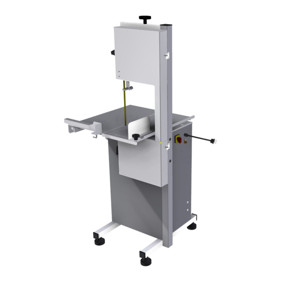
Band saw for bones, stainless steel, blade 2.180 mm/sierra
Hide thumbs
Also See for SL-218:
- Instruction manual (52 pages) ,
- Instruction manual (12 pages) ,
- Instruction manual (24 pages)

Subscribe to Our Youtube Channel
Related Manuals for Skymsen SL-218


Summary of Contents for Skymsen SL-218
- Page 1 BAND SAW FOR BONES, STAINLESS STEEL, BLADE 2.180 mm/SIERRA PARA HUESSOS INOXIDABLE, HOJA 2.180 mm. MODEL SL-218...
-
Page 2: Table Of Contents
SUMMARY 1. Introduction ..................3 1.1 Safety ........................3 1.2 Main Components ....................5 1.3 Technical Characteristics ..................6 2 – Installation and Pre Operation ............7 2.1 Installation ......................7 2.2 Pre Operation ....................... 7 3 . Operation ..................8 3.1 Starting ........................ -
Page 3: Introduction
1. Introduction 1.1 Safety When not properly used this equipment is a potentially dangerous machine. Maintenance, servicing, cleaning or any other operation shall be made by trained people. Plug has to be off outlet during any of these operations. Below instructions shall be respected to avoid accidents : 1.1.1 Read completely these instructions 1.1.2 To avoid to risk electric shocks and damage to the equipment never use it with wet clothes or shoes and/or standing on wet floors. - Page 4 1.1.13 This equipment has been developed for commercial operation, it is used for instance in restaurants, fast foods, hospitals, bakeries, butchers and similar. It is not recommended to use it - For continuous industrial production - A working ambient having a corrosive or explosive atmosphere, or contaminated with water vapour, dust or gas.
-
Page 5: Main Components
1.2 Main Components All components are manufactured with carefully chosen raw materials in accordance with Skymsen experience and testing standards. PICTURE 01 1 – Blade Tension Regulator Handle 8 – Movable Table 2 – ON/OFF Switch 9 – Staple 3 - Door 10-Thickness Guide 4 –... -
Page 6: Technical Characteristics
1.3 Technical Characteristics TABLE 01 CHARACTERISTICS UNIDAD SFL-218 Voltage Frequency Power Rating Height 1580 Width Depth Net Weight Shipping Weight Maximum Cutting Height Maximum Cutting Width Floor to Table Top Distance (L x P) mm 735 x 805 Table Dimensions... -
Page 7: Installation And Pre Operation
2 – Installation and Pre Operation 2.1 Installation 2.1.1 Placing the equipment The equipment must be installed over a firm and level working surface. See below drawing the recommended area 735mm Installation 805mm Area FRONT 2.1.2 Electric Installation The equipment has been designed to operate 220 Volts. When you receive the equipment check the voltage indicated on the cord label The power plug has 3 pins the middle pin is the ground . -
Page 8: Operation
3 . Operation 3.1 Starting To start the equipment follow the below instructions: 1 – Make sure all the protections and the door are in due place and the door is closed . 2 - Plug the equipment to the electric network, 3 –... -
Page 9: Operation Procedure
3.2 Operation Procedure 3.2.1 Make sure the equipment is steady on its working place. 3.2.2 Door The Door # 03 (Pic. 01) shall be closed as long as the equipment is in use. 3.2.3 Thickness Guide To obtain several same thickness slices adjust the Thickness Guide # 10 (Pic.01) as desired. That for turn the thickness guide handle counter clockwise getting the guide free, then place the Thickness Guide at the desired thickness and tight the Thickness Guide Handle turning it clockwise. - Page 10 Start the Machine To start the machine press the ON/OFF Switch button “I” (ON). Catch the Movable Table with the left hand and push against the Blade cutting the product at constant speed. After finishing the whole slice remove it with the right hand . The slice shall ALWAYS be removed behind the Blade to avoid the hand to contact the Blade Place the slices upon the Fixed Table # 11 (Pic.
-
Page 11: Cleaning And Sanitization
3.3 Cleaning and Sanitization IMPORTANT Unplug the equipment before to clean When the equipment must go through a complete cleaning and sanitization process: - Before to be used first time. - After every day end of operations - When the saw is not going to be used for a long period. - Before to start operation after a long period it has not been used. - Page 12 - Fixed Table Block Remove the Fixed Table Block # -1 (Pic. 04) just lifting it , see picture 04. PICTURE 04 - Blade Turn the Blade Tension Regulator Handle # 01 (Pic 05) counter clockwise to get the Blade # 02 (Pic.
- Page 13 - Lower Wheel Remove the Staple # 01 (Pic. 06) grab strongly the Lower Wheel and pull it to the front side of the equipment , see picture 06. PICTURE 06 - Upper Wheel First remove the Blade and grab strongly the Upper Wheel # 01 (Pic. 07) then lift it and pull it to the front side of the machine, see picture 07 PICTURE 07...
- Page 14 - Blade Tension Refulator Turn the Blade Tension Regulator Handle # 01 (Pic.08) counter clockwise until the Stretcher # 02 (Pic. 08) is completely removed. PICTURE 08 -Blade Tension Regulator Handle Remove the Blade tension Regulator Handle # 01 (Pic. 09) lifting it; PICTURE 09 Wash all the components with water and neutral soap.
- Page 15 IMPORTANT Do not spray water directly on the equipment Use a clean cloth or a soft brush to remove residues. Wash, sanitize, rinse and dry all the components. Assemble back all the components following the inverse path , and make sure all the components are correctly in place.
-
Page 16: Cautions With Stainless Steel
3.4 Cautions with Stainless Steel: The Stainless Steel may present rust signs, which ARE ALWAYS CAUSED BY EXTERNAL AGENTS, especially when the cleaning or sanitization is not constant and appropriate. The Stainless Steel resistance towards corrosion is mainly due to the presence of chrome, which in contact with oxygen allows the formation of a very thin protective coat. -
Page 17: General Safety Practices
4. GENERAL SAFETY PRACTICES IMPORTANT If any recommendation is not applicable to your equipment , please ignore it . The following safety instructions are addressed to both the operator of the machine as well as the person in charge of maintenance. The machine has to be delivered only in perfect conditions of use by the Distributor to the user. -
Page 18: Safety Procedures And Notes Before Switching The Machine On
given for each operation step. Every step of the operation shall be taken only if a sign has been made and responded. 4.1.3 Advices * In case of power shortage, immediately switch the machine off.* Use recommended or equivalent lubricants, oils or greases. * Avoid mechanical shocks, once they may cause damages or bad functioning. -
Page 19: Operation
4.3.2 Precautions Check the motor and sliding or turning parts of the machine in case of abnormal noises. Check the tension of the belts and chains and replace the set when belts or chains show signs of wearing. When checking the tension of belts or chains DO NOT insert your fingers between belts and pulleys, nor between the chains and gears. -
Page 20: Analysis And Problem Solving
5 . Analysis and Problem Solving 5.1 Problems, Causes and Solutions The equipments have been designed to need minimum maintenance, however, some performance failures may happen due mainly to natural worn out, caused by the use of the equipment. If some problems arise with your equipment check Table - 02 below where there are detailed some possible solutions. - Page 21 TABLE 02 PROBLEMS CAUSES SOLUTIONS Lack of power. Check if there is electric The equipment does not power. switch on. Problem with the internal or Call Technical Assistance. external electric circuits . Problem with the internal or Smoke or burn smell. Call Technical Assistance.
-
Page 22: Maintenance
6. Maintenance Maintenance must be considered a set of procedures with the purpose to keep the equipment best operating conditions , therefore increasing the equipment life and safety. Cleaning – check item 3,3 Cleaning Wiring - Check all wires regarding deteriorate conditions as well as all electric contacts (terminals) regarding tightening and corrosion . -
Page 23: Electric Diagram
7. Electric Diagram ELECTRIC NETWORK 220V / 50Hz 1L1 3L2 5L3 13 A1+ CWC 09 ON/OFF 2T1 4T2 6T3 14 A2- T1,T5 T4,T8... - Page 24 SUMARIO 1. INTRODUCCIÓN ................. 3 1.1 Seguridad ......................3 1.2 PRINCIPALES COMPONENTES ................. 5 1.3 Caracteristicas Tecnicas ..................6 2. Instalación y Pre Operación ............... 7 2.1 Instalación ......................7 2.2 Pre Operación ......................7 3. Operación ..................8 3.1 Accionamiento ....................... 8 3.2 Procedimiento para la Operación .................
-
Page 25: Introducción
1. INTRODUCCIÓN 1.1 Seguridad Este equipo es potencialmente peligroso cuando usado incorrectamente. Es necesario realizar el mantenimiento, limpieza, y/ó cualquier servicio por una persona calificada y con el equipo desconectado de la red eléctrica. Las instrucciones abajo deberán ser seguidas para evitar accidentes: 1,1,1 Lea todas las instrucciones. - Page 26 1.1.12 Use guantes de acero durante la operación de corte. 1.1.13 Este equipo fue desarrollado para uso en cocinas comerciales, por ejemplo restaurantes, cafeterías, hospitales, panaderías, carnicerías ó similares. El uso de este equipo no se recomienda cuando: - El procedimiento de producción sea continuado en escala industrial. - El local de trabajo tenga un ambiente con atmósfera corrosiva, explosiva, contaminada con vapor de agua ó...
-
Page 27: Principales Componentes
1.2 PRINCIPALES COMPONENTES Todos los componentes que incorporan la maquina son construidos con materiales cuidadosamente seleccionados para su función, dentro de los padrones de prueba y de la experiencia de SIEMSEN. 01 - Manija del Calibrador de la Hoja 08 - Mesa Movible 02 - Llave Prende/Apaga 09 - Presilla 03 - Puerta... -
Page 28: Caracteristicas Tecnicas
1.3 Caracteristicas Tecnicas TABLA 01 CARACTERISTICAS UNIDAD SFL-218 Voltaje Frecuencia Potencia Altura 1580 Ancho Profundidad Peso Neto Peso Bruto Ancho Max. de Corte Altura Max. de Corte Dimensiones Abiertas (L x P) mm 735 x 805 Distancia del suelo hasta la mesa... -
Page 29: Instalación Y Pre Operación
2. Instalación y Pre Operación 2.1 Instalación 2.1.1 Posicionamiento El equipo debe ser posicionado sobre una superficie firme y nivelada. Vea en el dibujo abajo el área necesaria para su instalación. 735mm Área para 805mm instalación FRENTE 2.1.2 Instalación Eléctrica Este equipo fue diseñado para 110 V . -
Page 30: Operación
3. Operación 3.1 Accionamiento Para prender el equipo siga las instrucciones abajo : 1-. Verifique si TODAS las protecciones están debidamente posicionadas y la puerta cerradas 2- Conecte el equipo a la red eléctrica ; 3 - Presione la llave Prende/Apaga No. 01 (Fig 02) para la posición “I” y la maquina se prende. -
Page 31: Procedimiento Para La Operación
3.2 Procedimiento para la Operación 3.2.1 Verifique si el equipo está firme en su local de trabajo. 3.2.2 Puerta La puerta No.03 (Fig.01) debe estar debidamente cerrada durante la operación 3.2.3 Regulador de corte Para realizar varios cortes de la misma espesura , ajuste el Regulador de Corte No.10 (Fig.01) como deseado. - Page 32 Antes de prender la maquina: Tire la Mesa Movble No. 08 (FIg.01) totalmente para la frente de la maquina Coloque el producto a ser cortado sobre la Mesa Movible. Elija la espesura de la tajada a ser cortada y ajuste el Regulador de Corte No. 10 (Fig. 01). Ajuste la Guía de la Hoja No 06 (Fig.01) para que su altura sea la altura de la pieza a ser cortada, no mas.
-
Page 33: Limpieza Y Higienización
3.3 Limpieza y Higienización IMPORTANTE Retire la flecha de la toma eléctrica antes de iniciar la limpieza. El equipo debe ser totalmente limpio y higienizado, cuando : - Antes de usar por la primera vez - Después de la operación en cada día. - Siempre que no sea usado por un largo periodo de tiempo - Antes de poner el equipo en operación después de un largo periodo sin uso. - Page 34 - Taco Retire el Taco de la mesa Fija No 01 (Fig,04) levantándolo. FIGURA 04 - Hoja Gire la Manija del Calibrador de la Hoja No. 01 (Fig. 05) en el sentido ante horario hasta que la Hoja No. 02 (Fig.05) se suelte y esté libre para que sea removida; FIGURA 05...
- Page 35 - Volante Inferior Retire la Presilla No. 01 (Fig.06) , agarre firmemente el Volante Inferior y tírelo para la frente de la maquina ,hasta su completa retirada vea la Figura 06. FIGURA 06 - Volante Superior Después de haber retirado la Hoja agarre firmemente el Volante Superior No. 01 (Fig .07) empújelo para arriba y en seguida tírelo para la frente de la maquina., vea figura 07.
- Page 36 - Calibrador de la Hoja Gire la Manija del Calibrador de la Hoja No. 01 (Fig. 08) en el sentido ante horario hasta la completa remoción del estirador No. 02 (Fig 08). FIGURA 08 - Manija del Calibrador de la Hoja Retire la Manija del Calibrador de la Hoja No.
- Page 37 IMPORTANTE No use chorros de agua directamente sobre la maquina. Use un paño limpio ó un cepillo blando para remover residuos impregnados. Lave, higienice, enjuague y seque todas las partes.. Monte de vuelta todos los componentes de la maquina en el orden inverso al del desmontaje , averiguando que todos estén correctamente montados.
-
Page 38: Cuidados Con Los Aceros Inoxidables
3.4 Cuidados con los aceros inoxidables Los aceros inoxidables pueden presentar puntos de “herrumbre”, que SIEMPRE SON PROVOCADOS POR AGENTES EXTERNOS, principalmente cuando el cuidado con la limpieza o higienización no sea constante y adecuado. La resistencia a la corrosión del acero inoxidable se debe principalmente a la presencia del cromo que, en contacto con el oxígeno, permite la formación de una finísima camada protectora. -
Page 39: Nociones Generales De Seguridad
4. Nociones Generales de Seguridad IMPORTANTE En el caso de algun item de las NOCIONES GENERALES DE SEGURIDAD no ser aplicable en su producto, por favor desconsiderar el mismo. Las Nociones Generales de Seguridad fueran elaboradas para orientar y instruir adecuadamente a los operadores de las maquinas y aquellos que serán responsables por su manutención. -
Page 40: Cuidados Y Observaciones Antes De Prender La Maquina
Cada función o procedimiento de operación y manutención debe estar completamente claro. El accionamiento de un comando manual ( botón , pulsante, llave eléctrica , palanca , etc ) debe ser hecho solamente cuando se tenga la certidumbre que es el comando correcto. En caso de falta de energía eléctrica , desligue la llave eléctrica inmediatamente. -
Page 41: Operación
Verifique las protecciones y los aparatos de seguridad para que siempre estén en perfecto funcionamiento. Verifique la tension de las correas y caso presenten desgaste haga su sustitución. 4.4 Operación 4.4.1 Avisos No trabaje con pelo largo que podría tocar cualquier parte de la maquina , pues podría causar serios accidentes . -
Page 42: Analisis Y Resolución De Problemas
5. Analisis y Resolución de Problemas 5.1 Problemas, Causas y Soluciones Las Sierras , fueran diseñadas para que necesiten un mínimo de manutención . Sin embargo pueden ocurrir algunas irregularidades en su funcionamiento , debido al desgaste natural causado por su uso . Caso haya algún problema con su maquina , verifique la Tabla –... - Page 43 TABLA 02 PROBLEMAS CAUSAS SOLUCIONES Falta de Energía Eléctrica Averigüe si hay energía eléctrica La maquina no se prende Problema con el circuito Interno o externo de la maquina Llame el Servicio Técnico Llame el Servicio Técnico Problema con el circuito Interno Olor de quemado o humo o externo de la maquina Correa patinando...
-
Page 44: Mantenimiento
6. Mantenimiento - El mantenimiento debe ser considerado como un conjunto de procedimientos con el objetivo de conservar el equipo en las mejores condiciones de funcionamiento propiciando un aumento de su vida útil y de su seguridad . - Limpieza verificar el ítem No. 3.3 de este manual . - Cableado - verifique todos los cables cuanto a su deterioración y todos los terminales cuanto a su aprieto y corrosión. -
Page 45: Diagrama Electrico
7. Diagrama Electrico RED ELÉCTRICA 110V / 60 Hz 220V / 50Hz 1L1 3L2 5L3 13 A1+ CONTACTORA PRENDE/ APAGA 2T1 4T2 6T3 14 A2- T1,T5 T4,T8... - Page 46 ___________________________________________________________ ___________________________________________________________ ___________________________________________________________ ___________________________________________________________ ___________________________________________________________ ___________________________________________________________ ___________________________________________________________ ___________________________________________________________ ___________________________________________________________ ___________________________________________________________ ___________________________________________________________ ___________________________________________________________ ___________________________________________________________ ___________________________________________________________ ___________________________________________________________ ___________________________________________________________ ___________________________________________________________ ___________________________________________________________ ___________________________________________________________ ___________________________________________________________ ___________________________________________________________ ___________________________________________________________ ___________________________________________________________ ___________________________________________________________ ___________________________________________________________ ___________________________________________________________ ___________________________________________________________ ___________________________________________________________ ___________________________________________________________ ___________________________________________________________ ___________________________________________________________ ___________________________________________________________ ___________________________________________________________ ___________________________________________________________ ___________________________________________________________ ___________________________________________________________ ___________________________________________________________...
- Page 47 ___________________________________________________________ ___________________________________________________________ ___________________________________________________________ ___________________________________________________________ ___________________________________________________________ ___________________________________________________________ ___________________________________________________________ ___________________________________________________________ ___________________________________________________________ ___________________________________________________________ ___________________________________________________________ ___________________________________________________________ ___________________________________________________________ ___________________________________________________________ ___________________________________________________________ ___________________________________________________________ ___________________________________________________________ ___________________________________________________________ ___________________________________________________________ ___________________________________________________________ ___________________________________________________________ ___________________________________________________________ ___________________________________________________________ ___________________________________________________________ ___________________________________________________________ ___________________________________________________________ ___________________________________________________________ ___________________________________________________________ ___________________________________________________________ ___________________________________________________________ ___________________________________________________________ ___________________________________________________________ ___________________________________________________________ ___________________________________________________________ ___________________________________________________________ ___________________________________________________________ ___________________________________________________________...
- Page 48 METALÚRGICA SIEMSEN LTDA. CNPJ: 82.983.032/0001-19 Rodovia Ivo Silveira - km 12, nº 9525, Galpão 1 - Bairro: Bateas - CEP: 88355-202 Brusque - Santa Catarina - Brasil Fone: +55 47 3211 6000 - Fax: +55 47 3211 6020 www.siemsen.com.br - comercial@siemsen.com.br 64963.5 - ENGLISH/ESPAÑOL Data de Correção: 27/02/2018 Besides this equipment, a complete range of other products are manufactured , consult our dealers...
Need help?
Do you have a question about the SL-218 and is the answer not in the manual?
Questions and answers