Advertisement
Quick Links
EXPLORE
®
with Screen Share
Assembly Instructions
Monitor Display Requirements: your flat panel display must confirm to the following
requirements.
With the stand removed, the monitor must not exceed 40 lbs.
y
Feature a mounting hole pattern 200mm x 200mm or smaller.
y
HDMI input with native resolution of 1080p.
y
Return to the last HDMI input programmed when powered on.
y
Sleep mode must be disabled to use the Power Controller.
y
Teaming Table with Screen Share is optimized to mount monitors up to 40" but can
y
accommodate a larger display as long as it meets the above specifications. Always check
monitor specifications before purchasing your display.
Bretford provides some Allen wrenches required for assembly but you will need the
following tools to complete your installation.
Phillips screw driver with large head
y
Phillips screw driver with small head
y
Wire cutters
y
Wire strippers
y
Scissors
y
This product includes electronic hardware and should be installed by a qualified individual.
Installation time of 4 hours or more for this table should be expected.
Two people are suggested when setting the angle and position of your monitor.
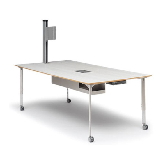
4-Leg Teaming Table
Advertisement

Subscribe to Our Youtube Channel
Related Manuals for Bretford EXPLORE


Summary of Contents for Bretford EXPLORE
- Page 1 Always check monitor specifications before purchasing your display. Bretford provides some Allen wrenches required for assembly but you will need the following tools to complete your installation. Phillips screw driver with large head...
- Page 2 012-0753 - Qty 1 Pole Cap 015-0175 - Qty 4 015-0045 - Qty 4 2 1/2” Stem Caster w/Brake 012-0761 - Qty 2 Threaded Glide (Comes Installed into Lower Legs) Plastic Cord Clip EXPLORE 4-Leg Teaming Tables with Screen Share...
- Page 3 Display Courtesy Hardware Pack Metric M4x12 screws Metric M4x30 screws Metric M5x12 screws Metric M5x30 screws Display hardware Metric M6x12 screws pack Contents Metric M6x35 screws Small washers Large washers 5/8” Large spacers EXPLORE 4-Leg Teaming Tables with Screen Share...
- Page 4 X40 Controller 018-0692 X40 HDMI Switch 018-0688 Cable Cubby 1400 023-1005 HDMI Ultra 12’ Cable 023-1006 HDMI “Show Me” Cable, 6’ 023-1007 X40/60 RS232 Control Cable 080-1000 Extron Installation Guide - X40 & X60 EXPLORE 4-Leg Teaming Tables with Screen Share...
- Page 5 Assembly Instructions 017-0519 (2)X 030-0354 (4)X EXPLORE 4-Leg Teaming Tables with Screen Share...
- Page 6 Assembly Instructions 022-3203 SC1054 (1) 4X (7) 4X EXPLORE 4-Leg Teaming Tables with Screen Share...
- Page 7 Assembly Instructions For glide version tables only. Skip this step if your table has casters. 015-0045 (4)X 017-1170 (4)X EXPLORE 4-Leg Teaming Tables with Screen Share...
- Page 8 Tables using casters are height adjustable from 22” to 32” at time of assembly. 030-0396 (2) 4X Set screws are pre-installed in your upper legs and need only be loosened to insert lower leg section. EXPLORE 4-Leg Teaming Tables with Screen Share...
- Page 9 Assembly Instructions 010-4889 (1)X End with threaded holes should face down towards table surface. 010-4381 (1)X 030-1129 (1)X 030-1128 (4)X EXPLORE 4-Leg Teaming Tables with Screen Share...
- Page 10 Optimized for flat panels up to 40” with no larger than a 200mm X 200mm mounting hole pattern. The mount can accommodate a larger monitor as long as it meets the specifications on the first page. Monitor weight may not exceed 40 lbs. EXPLORE 4-Leg Teaming Tables with Screen Share...
- Page 11 #044-2124. Follow this step for monitors that use a 100mm x 100mm mounting hole pattern. 030-1234 (4)x Longer M4 screws are available in the courtesy hardware pack if required. EXPLORE 4-Leg Teaming Tables with Screen Share...
- Page 12 Tighten to secure in place. Monitor not Quick release lever – Pull out shown for to insert into tube and adjust clarity monitor mount height. For stability, Monitor mount must install facing the work surface. EXPLORE 4-Leg Teaming Tables with Screen Share...
- Page 13 Position your monitor to be horizontal with the table top. Using a 1/8” Allen wrench provided, tighten the set screw to prevent rotational swivel. Two people are suggested when setting the angle and position of your monitor. EXPLORE 4-Leg Teaming Tables with Screen Share...
- Page 14 Install the two 2-outlet power modules into the Cable Cubby using the lock washers, black screws, and small screw driver provided by Extron. Bretford recommends you install them to the middle height setting. Install one power unit for each Cable Cubby door and install both so they are closest to the monitor.
- Page 15 There are four aluminum sleeves, use the shorter aluminum sleeves and discard the longer pair. Fill unused holes in the plastic cable plate with the plastic buttons provided. EXPLORE 4-Leg Teaming Tables with Screen Share...
-
Page 16: Isometric View
Assembly Instructions Feed the assembly up through the bottom of the Cable Cubby and secure in place at the lowest position using the lock washers and black screws provided by Extron. EXPLORE 4-Leg Teaming Tables with Screen Share ISOMETRIC VIEW... - Page 17 Cable Cubby into the table. 018-0688 (1)X Slide the latch brackets up until they are snug to the underside of the work surface and lift the lever upward to lock into place. EXPLORE 4-Leg Teaming Tables with Screen Share...
- Page 18 Extron mounting brackets MBU123; The X60 (TeamWork 600) 6-user HDMI switch utilizes Extron mounting brackets MBU149; The X42 (TeamWork 601) 6-user (4)HDMI/(2)VGA switch utilizes Extron mounting brackets MBU123. Install the rubber bumpers provided by Extron to the top of the TeamWork Switch. EXPLORE 4-Leg Teaming Tables with Screen Share...
- Page 19 Assembly Instructions Strip approximately 1” of the black cover off of the short extension from each of the Show Me cables. Expose and separate the Red, Black and bare wires as shown. EXPLORE 4-Leg Teaming Tables with Screen Share...
- Page 20 Tx Rx G Rx G X42 four user switch Using the small screwdriver provided, tighten the tally port screws to each wire and secure the cables into place using the thin white cable ties provided. EXPLORE 4-Leg Teaming Tables with Screen Share...
- Page 21 Use the hooks to initially hang the bin while installing the electronics. Swing and open wide enough to organize the power and data cables inside the cord bin. Hooks are screwed in to most outboard holes. 030-1806 060-1127 (2)X (1)X EXPLORE 4-Leg Teaming Tables with Screen Share...
- Page 22 C G T C G T Tx Rx G Rx G X42 Six user switch shown Pull the excess Show Me cables out of the Cable Cubby and rest them neatly on the work surface. EXPLORE 4-Leg Teaming Tables with Screen Share...
- Page 23 Switch. The other end will run under the table, through the small grommet hole, up the monitor pole and to your display monitor input HDMI port. Use the pole cable clips to secure the wire into place. Store extra cable in the cord management bin once installed. EXPLORE 4-Leg Teaming Tables with Screen Share...
- Page 24 X42 Six user switch shown System Controller Switcher (IPL T PC1) (SW4 HDMI) RS-232 AUTO Tx Rx 4 pole connector 5 pole connector (to system controller) (to switcher) Switcher Control Cable X40 Four user cable shown EXPLORE 4-Leg Teaming Tables with Screen Share...
- Page 25 MBU bracket. Fit the bracket over the screws and slide away from you (towards the center of the table). Once in place tighten the screws. LED lights and buttons face out from the table. EXPLORE 4-Leg Teaming Tables with Screen Share...
- Page 26 Insert the wood screws loosely, fit the bracket over the screws and slide away from you (towards the center of the table). Once in place tighten the screws. LED lights and buttons face out from the table. EXPLORE 4-Leg Teaming Tables with Screen Share...
- Page 27 Power cables should be secured to the rear of the bin while excess Show Me data cables should be housed in the front of the bin. Show Me cables should be left loose to enable them to be pulled out of the Cable Cubby for use. EXPLORE 4-Leg Teaming Tables with Screen Share...
- Page 28 Plug your display monitor power cord into the Power Controller using the “Power Output” plug. Plug your Power Controller into the ECF6 power strip. 100-120V 50/60Hz LISTED 17TT AUDIO/VIDEO APPARATUS INPUT 12A MAX POWER OUTPUT 12A MAX EXPLORE 4-Leg Teaming Tables with Screen Share...
- Page 29 Once plugged in ensure the ECF6 power strip on/off switch is in the on position, the switch will illuminate when turned on. EXPLORE 4-Leg Teaming Tables with Screen Share...
-
Page 30: Testing The System
Male 19-pin HD Male 19-pin HD (HDMI connector) (HDMI connector) Three-conductor Share Button pigtail for contact closure and tally EXPLORE 4-Leg Teaming Tables with Screen Share SWITCHER SOURCE/LAPTOP END (input) (output) Three-conductor Male 15-pin HD Share Button Male 15-pin HD... - Page 31 Fax: 847-678-0852 BRETFORD.COM Bretford, B design, and EXPLORE are trademarks or registered marks of Bretford Manufacturing, Inc. or Bretford Manufacturing, Ltd. Patents pending. ©2015 Bretford Manufacturing, Inc. All rights reserved. All other referenced product names and logos are trademarks of their respective owners.
Need help?
Do you have a question about the EXPLORE and is the answer not in the manual?
Questions and answers