Advertisement
Quick Links
Advertisement

Subscribe to Our Youtube Channel
Related Manuals for EGO LB4800E


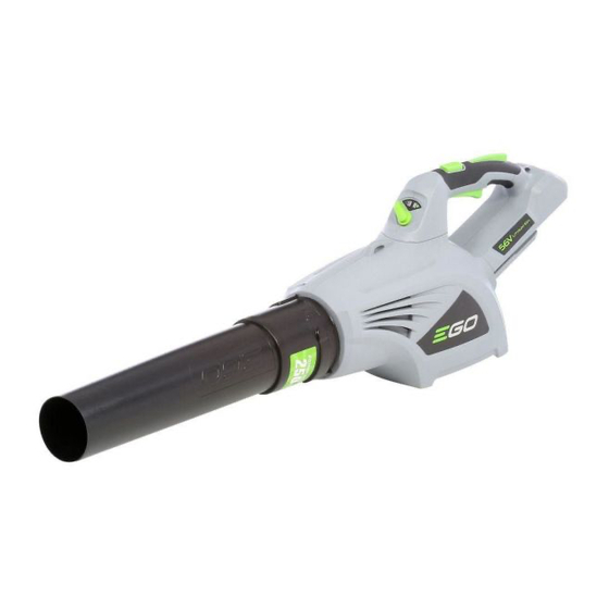
Summary of Contents for EGO LB4800E
- Page 1 REPAIR GUIDELINE Blower_LB4800E Version: 1 Issue Date: 2015/03/05...
- Page 2 Table of Contents Contents Page Troubleshooting Tool list for repair Replace the ducted set Replace the parts in the handle set 10-11...
- Page 3 Troubleshooting Problem Possible Cause Fault Position Test & Solution PCB is broken PCB in Handle set Replace PCB in the handle set. Measure the resistance between any Fail to start PCB in Handle set, two cables of the three cables in the Both PCB and motor are Motor in Ducted ducted set by using a multimeter.
- Page 4 Tool List For Repair Tool List SPEC Remark Magnetic bits Heat gun Heat -shrinkable sleeves Scissors To remove the shrinkable sleeve...
- Page 5 Replace the Ducted Set 1. Loose and remove the six screws in the right housing cover and open the housing. Handle Set Right Housing Cover Right Fan Baffle Ducted Set Description Part Number Description Part Number Ducted Set 2823629000 Tapping Screw 5610032000 Left Fan Baffle 3127205000...
- Page 6 Replace the Ducted Set 2. Take out the internal wires and connectors from the grooves of housing. 3. Remove the heat-shrinkable sleeve from the connectors with a scissor. 4. Move the transparent sleeve aside and pull the connectors to separate.
- Page 7 Replace the Ducted Set 5. Remove the six screws in the right fan baffle, then take the right fan baffle off. 6. Take out the ducted set. Replace with a new ducted set if it is damaged. 7. The left and right fan baffle can be replaced if they are broken or worn. 8.
- Page 8 Replace the Ducted Set 9. Move the transparent sleeve and heat-shrinkable sleeves to cover the connectors and use a hot air gun to shrink the sleeves. 10. Place the magnet ring into the slot between the new ducted set and the housing, press it firmly under the new ducted set.
- Page 9 Replace the Ducted Set 12. Align the cables in the grooves. 13. Mount the right fan baffle onto the ducted set and lock it with six screws. 14. Close the right housing and lock it with six screws. cable alignment...
- Page 10 Replace the parts in the handle set 1. Following the instructions in “Replace the ducted set” to open the right housing cover. 2. Loose and remove six screws in the right handle housing cover and open the handle housing. 3. Replace the handle housings or any parts in the handle set if they are broken or worn. (as shown in the next page) 4.
- Page 11 Replace the parts in the handle set Boost Button Speed Lock-off Lever Spring 4 Description Part Number Ajusting Knob Battery Release Spring 3 3127201000 Button Spring 1 Latch 3127202000 Battery Ejection Lever 3127206000 Lock-off Lever 3127212000 Trigger Trigger 3127211000 Battery Boost Button 3127214000 release...
Need help?
Do you have a question about the LB4800E and is the answer not in the manual?
Questions and answers