Table of Contents
Advertisement
Quick Links
Advertisement
Table of Contents

Subscribe to Our Youtube Channel
Related Manuals for Neuation iFuge M12P


Summary of Contents for Neuation iFuge M12P
- Page 1 M12P...
- Page 3 1. Product Description..............1.1 Introduction 1.2 Intended Use 1.3 Salient Features 1.4 Standard Accessories 1.5 Technical Specifications 2. Safety Precautions..............3. Installation................3.1 Location 3.2 Connecting Power Adaptor 4. Standard Parts Listing..............5. User Interface and Display............6. Rotor Installation..............6.1 Rotors and Accessories 6.2 Rotor Removing &...
-
Page 4: Intended Use
1. PRODUCT DESCRIPTION 1.1 INTRODUCTION Congratulation! You are using the table top genius high speed micro centrifuge. The product is equipped with a maintenance free drive, a large display & a simple interface for silent & efficient operation for daily lab usage. This next generation micro centrifuge can be operated via USB with facility of data logger and comes with a host of safety features including imbalance detection. -
Page 5: Product Description
1. PRODUCT DESCRIPTION 1.3 SALIENT FEATURES Centrifuge has following features: Imbalance detector with auto cutoff. Large back light digital LCD display. High centrifugal force which delivers 15000 RPM/15596 x g RCF. USB port for remote terminal control capability. Remote operation with data logger. Lid safety interlock & auto lid open Convenient and easy user interface. - Page 6 1. PRODUCT DESCRIPTION 1.5 TECHNICAL SPECIFICATIONS Motor Type Brushless DC Motor Maximum Speed 15000 rpm Run Time 30 secs to 999 mins & infinite mode Speed Setting Variable 500 - 15000 rpm Speed Accuracy ± 100 rpm Maximum Volume 12 x 2 ml (microtubes) 15596 x g Maximum RCF Ambient Temperature...
- Page 7 Never use the centrifuge in any manner not specified in this manual. Equipment used in any manner not specified in this manual or by the manufacturer, the protection provided by the equipment may be impaired. Never move the centrifuge while the rotor is spinning. ...
-
Page 8: Safety Precautions
2. SAFETY PRECAUTIONS Do not lean on the equipment. It may damage the equipment or the harm the operator. When moving the centrifuge from a cold room to a normal room, run the centrifuge for 30 minutes beforehand in the cold room to avoid condensation. -
Page 9: Installation
3. INSTALLATION The table top genius is supplied in a box. Open the box, then remove the packaging and gently take the centrifuge out of the box. Before 1st time usage, open the centrifuge & ensure to remove all packaging from the rotor chamber &... - Page 10 4. STANDARD PARTS LISTING Centrifuge Lid Lid Lock Pin Aluminum Protection Lid Rotor Lid Nut Rotor Lid Rotor Display Control Panel USB Port Power Adaptor ON/OFF Port Switch Emergency Suction Cups Lid Release...
-
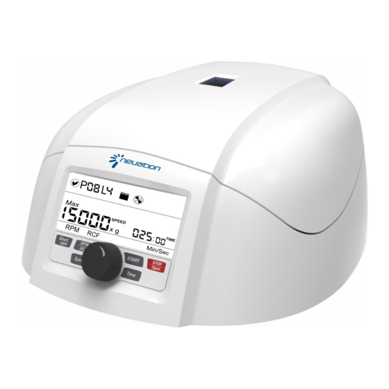
Page 11: User Interface & Display
5. USER INTERFACE & DISPLAY Item Name Function Press button to STOP the ongoing operation. Lid STOP/OPEN opens automatically, after rotor comes to a stop. BUTTON Press button to select SPEED mode. Then rotate SPEED SETTING KNOB to set desired run SPEED. BUTTON Press button to select TIME mode. Then rotate TIME SETTING KNOB to set desired run TIME. - Page 12 5. USER INTERFACE & DISPLAY Item Symbol Description Indicates lid status. Left image = lid close & Right image = lid open. Indicates centrifuge status. When centrifuge is running the symbol rotates and when centrifuge is not running the symbol is stable. Indicates the speed value at which centrifuge is running.
-
Page 13: Rotor Installation
6. ROTOR INSTALLATION Below table shows the rotors which are compatible with the centrifuge & its Max. RCF with different tubes & adaptors. 1.5/2.0ml tubes 0.5ml/0.4ml Adaptor 0.2ml Adaptor 12 tubes rotor 0.5 ml 0.4 ml Max. Speed 15000 15000 15000 15000 Max. - Page 14 6. ROTOR INSTALLATION 6.2 ROTOR REMOVING AND REPLACING PROCESS Upon reception of centrifuge, the rotor comes pre-installed. In case if you want to remove or replace rotor, follow the below mentioned procedure. 6.2.1 REMOVING ROTOR Do not remove or loosen the rotor lid before attempting to remove rotor.
- Page 15 6. ROTOR INSTALLATION 6.3 BALANCING THE ROTOR 1. Always balance the rotor before centrifugation. Following are symmetrical loading of centrifuge tubes to rotor. 2. The above is the correct method of loading the tubes in the rotor. The samples in the tubes should be of equal volume. 3.
-
Page 16: Operating The Centrifuge
7. OPERATING THE CENTRIFUGE 7.1 SWITCH ON THE CENTRIFUGE Switch : ON After connecting the power adaptor, switch ON the power mains & the switch at the rear side of the centrifuge. Make sure to check the rotor fitment before use. Centrifuge will not operate with open lid. NOTE: Maintain a gap of 3 seconds between switch OFF and switch ON again. - Page 17 7. OPERATING THE CENTRIFUGE 2. Pressing the speed button “TWICE” will make the speed change in interval of 100s. For example: if speed is 10000 rpm, then next speed will be 10100 rpm. 3. Pressing the speed button more than 2 times will again start the process from point 1.
- Page 18 7. OPERATING THE CENTRIFUGE Press “START BUTTON” to start operation and press “STOP/OPEN BUTTON” to stop the ongoing operation. When the centrifuge is running the symbol “ ” will be rotating. Pressing the “STOP/OPEN BUTTON” will stop the operation as well as it will open the centrifuge lid automatically once the rotor comes to a stop.
-
Page 19: Imbalance Detection
7. OPERATING THE CENTRIFUGE Emergency Lid Release pin Push Down using any tool 7.6 IMBALANCE DETECTION The centrifuge is equipped with an imbalance detection safety feature. When the rotor is not loaded symmetrically, the imbalance detector gets activated and will cut off the centrifugation. The error "Err 55" will be shown on the display. -
Page 20: System Requirement
8. REMOTE OPERATION & PROGRAMMING For programming and remote operation the centrifuge needs to be connected to a computer. 8.1 SYSTEM REQUIREMENT The GUI software and data logger file required the following minimum system requirement to operate: Operation System: Windows® 7 with i3 Processor or more having 32 bit or 64 bit operating system and Windows®... - Page 21 8. REMOTE OPERATION & PROGRAMMING After connecting USB, display of centrifuge will show the USB connection. Top left symbol in centrifuge display indicates USB connection. Once the USB cord is connected, centrifuge unit controls will be disabled. The centrifuge can now be run using the program. Only the “STOP/OPEN BUTTON”...
- Page 22 8. REMOTE OPERATION & PROGRAMMING 8.4.1. COM PORT CONNECTING AND DISCONNECTING Once you connect the USB cable, the COM PORT for the centrifuge is detected automatically. Now click on the CONNECT button to connect shaker and computer for remote operation. After connection, the TEXT BOX will show “COM, M12P Connected”...
- Page 23 8. REMOTE OPERATION & PROGRAMMING 8.4.3. SETTING A PROGRAM Remote operation provides centrifugation with 99 programs and each of maximum 4 lines. It can be used to pre-set program for specific regular operations. User can save upto 99 programs according to their needs. The same can be used for the cases mentioned below: 1.
- Page 24 8. REMOTE OPERATION & PROGRAMMING Click on the PROGRAM SCROLL BUTTON to select the required program out of total 99 programs you wish to set. User can save up to 99 programs. Start with the 1 line click on the SPEED UP/DOWN BUTTON to select value of the specific line of the program.
- Page 25 8. REMOTE OPERATION & PROGRAMMING 8.4.5 PRE-SET PROGRAM SELECTION AND OPERATION Click on the PROGRAM SCROLL BUTTON to select the required pre-set program out of total 99 programs. After selecting required program, click on START BUTTON to start the operation. Operation will start from 1st line of selected program. There is a delay or pause of 8 seconds between all 4 lines.
- Page 26 8. REMOTE OPERATION & PROGRAMMING 3.4.7 ACTIVE LINE SPEED DISPLAY This SPEED UP/DOWN BOX is used to read speed value of active line of the program. For example: if line 3 of 46th program is running then this SPEED UP/DOWN BOX will display the speed value of line 3 of 46th program. It can be used to change the speed value of active line.
- Page 27 8. REMOTE OPERATION & PROGRAMMING 3.4.10 CENTRIFUGE LID STATUS The above images will be display in the screen according to the status of lid. This will be the indication to the user regarding lid status. 3.4.11 CENTRIFUGE STATUS This symbol shows the centrifuge status. When centrifuge is running the symbol rotates and when centrifuge is not running the symbol will be stable.
-
Page 28: Data Logger
8. REMOTE OPERATION & PROGRAMMING 8.4 DATA LOGGER The remote operation comes with data logger features. All operations performed through the GUI will be saved in a excel sheet. With the help of data logger user can view and take a print out of previously performed operations. -
Page 29: Maintenance And Cleaning
9. MAINTENANCE AND CLEANING 1. The rotor and the outside of the centrifuge should be cleaned regularly with a moist cloth. 2. Ensure that while cleaning the unit is not plugged in. 3. Wear protective gloves & safety glass while operating & cleaning the device. -
Page 30: Troubleshooting
10. TROUBLESHOOTING This centrifuge has a self – diagnostic function. If a problem occurs, an error/warning code will be displayed on the display screen and the operator can determine the malfunction with the warning code below. ERROR PROBLEM SOLUTION No display No main power Power check &... - Page 31 10. TROUBLESHOOTING ERROR PROBLEM SOLUTION Err 1 Lid latch Limit switch Open lid and close it is not pressed properly. Err 52 Rotor Stucked Turn OFF the centrifuge, Check & fit rotor properly & turn ON again. Power tripping Cable not fit properly. Remove cable and connect properly.
-
Page 32: Warranty Statement
11. WARRANTY STATEMENT This products is warranted to be free from defects in material and workmanship for a period of two (2) years from date of purchase. Your product will be duly repaired upon prompt notification in compliance with the following conditions : This warranty is valid only if the product is used for its intended purpose and within the guidelines specified in this instruction manual. - Page 33 11. WARRANTY STATEMENT The purchaser agrees that there is no warranty of merchantability or of fitness for any intended purpose and that there are no other remedies or warranties, expressed or implied, which extend beyond the description on the face of the agreement.
-
Page 34: Product Disposal
12. PRODUCT DISPOSAL In case the product is to be disposed of, the relevant legal regulations are to be observed. Information on the disposal of electrical and electronic devices in the European Community The disposal of electrical devices is regulated within the European Community by national regulations based on EU Directive 2012/19/EU on waste electrical and electronic equipment (WEEE).
Need help?
Do you have a question about the iFuge M12P and is the answer not in the manual?
Questions and answers