Table of Contents
Advertisement
Quick Links
Advertisement
Chapters
Table of Contents

Subscribe to Our Youtube Channel
Related Manuals for Shuttle Spacewalker HOT-685


Summary of Contents for Shuttle Spacewalker HOT-685
- Page 1 HOT-685 PPGA Celeron processor Based AGP MAIN BOARD User's Manual...
- Page 2 Trademarks Spacewalker is a registerred trademark of Shuttle Inc. Intel, Celeron is a registered trademarks of Intel Corporation. PC/ATX is a registered trademark of International Business Machines(IBM) Corporation PS/2 is a registered trademark of IBM Corporation.
- Page 3 Federal Communicationsr Commission (FCC) Compliance Notice This equipment has been tested and found to comply with the limits for a Class B digital device, pursuant to Part 15 of FCC Rules. These limits are designed to provide reason- able protection against harmful interference in a residential installation. This equipment generates, uses and can radiate radio frequency energy.
-
Page 4: Table Of Contents
ABLE ONTENTS ............5 HAPTER NTRODUCTION .............. 6 HAPTER EATURES Accessories of HOT-685 ................. 8 .......... 9 HAPTER ARDWARE NSTALLATION The Installation PPGA Celeron Processor ............9 Jumpers ......................10 CPU Clock Speed and ratio Selection - JP2, J113 and JP9 ......10 Special Tip for User's Reference Only............. -
Page 5: Chapter 1 Introduction
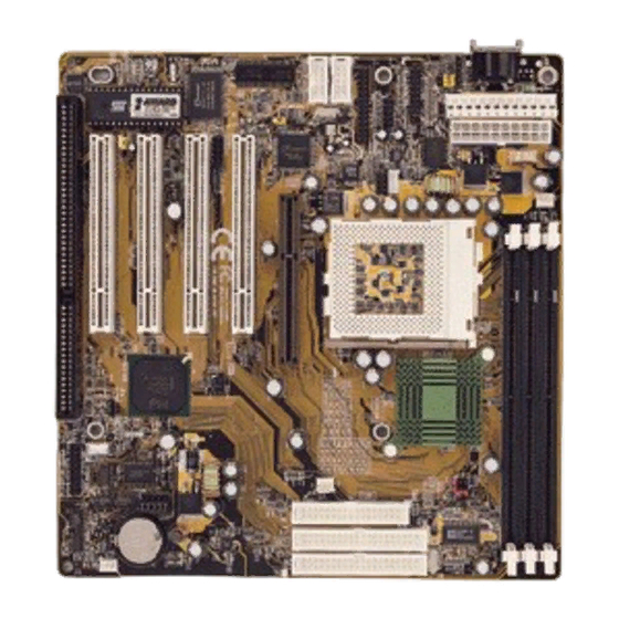
NTRODUCTION HOT-685 is a highly integrated IBM PC/AT compatible system board designed to meet the industry's most demanding desktop applications. Based on the Intel 82443BX AGPset chipset which support up to 500MHz PPGA Celeron processor with MMX technology. HOT-685 is equipped with an Accelerated Graphics Port (A.G.P.), a high-perfor- mance interconnect for graphic-intensive application, such as 3D applications. -
Page 6: Chapter 2 Features
EATURES The HOT-685 Mainboard is carefully designed for the demanding PC user who wants high performance and many intelligent features in a compact package: Chipset: Features Intel's 440BX AGPset with I/O subsystems. CPU Support: Intel PPGA Celeron processor 300 ~ 500 MHz. Versatile Memory Supports: Supports three banks of normal or PC/100 SDRAM maximum memory size up to 768 MB. - Page 7 Board Size: AT form factor, dimension 220mm x 230mm. Advanced Features: Low EMI -- Using built-in Spread Spectrum with 1.5% modulation and automatic clock shut- off of unused PCI/SDRAMS slots to reduce the Electromagnetic Interference (EMI). Dual Function Power Button (ATX power only) -- The system can be one of two states, one is Suspend mode and the other is the Soft-off mode.
-
Page 8: Accessories Of Hot-685
ACCESSORIES OF HOT-685 - 8 -... -
Page 9: Chapter 3 Hardware Installation
ARDWARE NSTALLATION The Installation PPGA Celeron Processor HOT-685 mainboard provides a 370-pin ZIF Socket370 for Intel PPGA Celeron CPU. The CPU that came with the mainboard should have a fan attached to it to prevent over- heating. If this is not the case then purchase a fan before you turn on your system. To install a CPU, first turn off your system and remove its cover. -
Page 10: Jumpers
Jumpers Several hardware settings are made through the use of jumper caps to connect jumper pins on the main board. The jumper's pin 1 on main board will be on the top or on the left when holding the main board with the keyboard connector away from yourself. Jumpers with two pins will be shown as for Close (On) and for Open (Off). -
Page 11: Special Tip For User's Reference Only
Special Tip for User's Reference Only HOT-685 mainboard provides a special Jumper J10 to overspeed your 66 MHz based Intel PPGA Celeron processor to 100 MHz. Normally, CPU Host Clock 100 ~ 150 MHz are not available for 66 MHz based processor. But, when pull out mini jumper from J10 (let it open), the user can Hard-Configure your 66 MHz based processor to 100 MHz based. -
Page 12: At And Atx Power Supply Connectors Setting - J112
AT and ATX Power Supply Connectors Setting - J112 The mainboard provides both 12-pin AT type and 20-pin ATX type power supply connectors. Jumper J112 is used to set which type of power supply is used. J112 Close (On) for AT Power Connector. J112 Open (Off) for ATX Power Connector. -
Page 13: Connectors
Connectors Front Panel Connectors (JP10) Speaker Connector - SPKER PC speaker connector may attach a 4-pin PC speaker cable from the case to this connector. HDD LED Connector - HDD-LED Attach a 2-pin IDE drive LED cable to this connector. The LED lights when an IDE device is active. - Page 14 Other Connectors AT and ATX Power Supply Connectors AT Power Connector is a 12-pin male header connector. Plug the connector from the power directly onto the board connector while making sure the pin 1 is in its position. The main board requires a power supply with at least 200 watts and "power good signal".
- Page 15 AT Keyboard & PS/2 Mouse Header or PS/2 Keyboard & PS/2 Mouse Connector AT Keyboard & PS/2 Mouse Header: One 5-pin female AT keyboard & one 5-pin PS/2 mouse header is located at the rear of the main board. The main board provides a 5-pin PS/2 mouse header for an optional PS/2 mouse cable.
- Page 16 IDE, Floppy, Parallel and Serial port connectors The mainboard package has included one 40-pin ribbon cable for IDE H.D.D, one 34-pin ribbon cable for F.D.D, one 25-pin ribbon cable for printer and two 9-pin ribbon cables for COM port devices. Flat cables should be connected with the red stripe on the pin 1 side of the conector.
- Page 17 Port SJ2 can be used to connect a modem audio line to HOT-685. You would use this connector when telephone answering machine software for input and output. SJ2 (TAD) pin assignment : 4 = MONO 3 = Ground 2 = Ground 1 = PHONE CD-IN Port SJ1 is used to attach a CD-ROM audio connector.
-
Page 18: Chapter 4 Memory Configuration
EMORY ONFIGURATION The HOT-685 mainboard provides three 168-pin DIMM sockets that make it possible to install from 8MB up to 768MB of SDRAM. The DIMM socket support 8MB, 16MB, 32MB, 64MB, 128MB and 256MB 3.3V single- or double- side SDRAM DIMM. The three DIMM sockets are arranged in three banks of one socket each. -
Page 19: Chapter 5 Flash Utility
LASH TILITY This chapter briefly discusses Award Flash utility in order to guide you through updating your old BIOS. The file name we use to program here is test.bin, and the file name to save old BIOS is 685.OLD. Please note that those file names are not absolute. - Page 20 If “Yes” To save the old BIOS: 1. Please respond “Y”, and then press the ENTER key. 2. Move the cursor to “File Name to Save: “ 3. Type file name “TEST.BIN”, and then press the ENTER key. (Your old BIOS will be saved in the file name you create.
- Page 21 BIOS S ETUP The BIOS ROM has a built-in Setup program that allows users to modify the basic system configuration. This type of information is stored in battery-backed RAM so that it retains the Setup information when the power is turned off. Entering Setup Power on the computer and press <Del>...
-
Page 22: The Main Menu
The Main Menu Standard CMOS Setup This setup page includes all items in a standard compatible BIOS. BIOS Features Setup This setup page includes all items of Award special enhanced features. Chipset Features Setup This setup page includes all items of chipset features. Power Management Setup This setup page includes all items of Power Management features. - Page 23 CPU Speed Setting This setup includes all items of CPU speed features. Integrated Peripherals This setup page includes all items of peripheral features. Supervisor Password Change, set, or disable supervisor password. It allows you to limit access to the system and Setup, or just to Setup. User Password Change, set, or disable user password.
-
Page 24: Standard Cmos Setup
Standard CMOS Setup Date The date format is <day>, <month> <date> <year>. Press <F3> to show the calendar. Time The time format is <hour> <minute> <second>. The time is calculated base on the 24-hour military-time clock. For example. 5 p.m. is 17:00:00. Hard Disks Type This item identify the types of hard disk drives that has been installed in the com- puter. - Page 25 Drive A type / Drive B type This item specifies the types of floppy disk drive A or drive B that has been installed in the system. Video This item selects the type of adapter used for the primary system monitor that must matches your video display card and monitor.
-
Page 26: Bios Features Setup
BIOS Features Setup Virus Warning When this item is enabled, the Award BIOS will monitor the boot sector and partition table of the hard disk drive for any attempt at modification. If an attempt it made, the BIOS will halt the system and the following error message will appear. Afterwards, if necessary, you will be able to run an anti-virus program to locate and remove the problem before any damage is done. - Page 27 Boot Sequence This item determines which drive computer searches first for the disk operating system. Default setting is A, C, SCSI. BIOS also support system boot from CD-ROM drive or SCSI hard disk drive. Swap Floppy Drive When this item enables, the BIOS will swap floppy drive assignments so that Drive A: will function as Drive B: and Drive B: as Drive A:.
- Page 28 PCI/VGA Palette Snoop This item must be set to enabled if there is a MPEG ISA card installed in the system, and disabled if there is no MPEG ISA card installed in the system. OS Select For DRAM > 64MB This item allows you to access the memory that over 64 MB in OS/2.
-
Page 29: Chipset Features Setup
Chipset Features Setup Auto Configuration The default setting of the optimal timings for items 3 through 7 for 60ns EDO DRAM modules. EDO DRAM Speed Selection This item set the EDO DRAM Read/Write timings that the system uses. When item of "Auto Configuration"... - Page 30 DRAM Idle Timer This item specifies the number of clocks that the DRAM controller will remain id IDLE state before precharging all pages. SDRAM CAS Latency Time When synchronous DRAM is installed, you can control the number of CLKs between when the SDRAMs sample a read command and when the controller samples read data from the SDRAMs.
- Page 31 Memory Hole At 15M-16M In order to improve performance, certain space in memory can be reserved for ISA cards. This memory must be mapped into the memory space below 16 MB. Passive Release When enabled, the chipset provides a programmable passive release mechanism to meet the required ISA master latencies.
-
Page 32: Power Management Setup
Power Management Setup Power Management This item determines the options of the power management function. Max Saving puts the system into power saving mode after a brief period of system inactivity; Min Saving is the same as Max Saving except the time of the system inactivity period is longer;... - Page 33 Doze Mode When enabled and after the set time of system inactivity, the CPU clock will run at slower speed while all other devices still operate at full speed. Standby Mode When enabled and after the set time of system inactivity, the fixed disk drive and the video would be shut off while all other devices still operate at full speed.
- Page 34 IRQ 8 Break Suspend You can turn On or Off monitoring of IRQ8 (the Real Time Clock) so it does not awaken the system from Suspend mode. ** Reload Global Timer Events ** If any of these items is set to Disabled, that system activity event will not be moni- tored to reload global timer.
-
Page 35: Pnp/Pci Configuration Setup
PNP/PCI Configuration Setup PNP OS Installed When this item is set to Yes, it will allow the PnP OS(Windows 95) control the system resources except PCI devices and PnP boot devices. Default setting is No. Resources Controlled By The Award Plug and Play BIOS has the capability to automatically configure all of the boot and Plug and Play compatible devices. - Page 36 If you have equipped your system with a PCI controller, changing this allows you to specify which slot has the controller and which PCI interrupt (A, B, C or D) is associ- ated with the connected hard drives. Remember that this setting refers to the hard disk drive itself, rather than individual partitions.
-
Page 37: Cpu Features Setup
CPU Features Setup Auto Detect DIMM/PCI Clk Enabling this item allows system auto detect and close clock signal to empty DIMM/ PCI slot to reduce EMI. Spread Spectrum This item allows the user to enable Spread Spectrum Modulated to reduce the EMI. (Listed items will show up when optional hardware monitor present) CPU Warning Temperature Since the mainboard support CPU temperature monitoring and overhear alert. - Page 38 Current CPUFAN1/2/3 Speed The mainboard can detect three fans rotation speed for CPU cooler and system. IN0(V) ~ IN2(V), +5V ~ -5V, +12V ~ -12V The mainboard support CPU and mainboard voltages monitoring. The onboard hardware monitor is able to detect the voltages output of the voltage regulators and power supply.
-
Page 39: Integrated Peripherals
Integrated Peripherals IDE HDD Block Mode This item is used to set IDE HDD Block Mode. If your IDE Hard Disk supports block mode, then you can enable this function to speed up the HDD access time. If not, please disable this function to avoid HDD access error. IDE Primary Master PIO In this items, there are five modes defined in manual mode and one automatic mode. - Page 40 IDE Primary Master UDMA On this mainboard, Intel PIIX4 improves IDE transfer rate using Bus Master UltraDMA/33 IDE which can handle data transfer up to 33MB/sec. The options are Disabled, Enabled and Auto, Auto is the default settings for on board Primary Master UltraDMA33.
- Page 41 POWER ON Function This item is used to defined Keyboard & PS/2 mouse power-on function enabled or disabled. The options are Button Only, HOT-Key and PS/2 Mouse. Button Only - Only soft-on/off button on the front panel is available. KB Power ON Password This item set the keyboard power-on password.
- Page 42 Parallel Port Mode This item specifies onboard parallel port mode. The options are SPP (Standard Parallel Port), EPP(Enhanced Parallel Port), ECP (Extended Capabilities Port), and EPP+ECP. ECP Mode Use DMA This item specifies DMA (Direct Memory Access) channel when ECP device is in use.
-
Page 43: Password Setting
Password Setting This section describes the two access modes that can be set using the options found on the Supervisor Password and User Password. Supervisor Password and User Password The options on the Password screen menu make it possible to restrict access to the Setup program by enabling you to set passwords for two different access modes: Supervisor mode and User mode. - Page 44 FM801 PCI Audio Controller Software Installation User's Guide - 1 -...
- Page 45 ABLE ONTENTS 1.SPECIFICATION....................3 2.DRIVER INSTALLATION.................4 2.1Windows95/98 Driver Installatioin..................4 2.1.1Installing FM801 Audio Controller Windows95/98 Driver..........4 2.1.2Verifying the FM801 Driver Installation for Win95/98............. 8 2.1.Q3D Control Panel......................10 2.1.4Driver un-installation......................13 2.2Windows NT 4.0 Driver Installatioin..................14 2.2.1Installing FM801 Audio Controller Driver...............14 2.2.2Verifying the FM801 installation for Win NT 4.0............18 2.2.3Windows NT4.0 Driver Un-installation................20 2.3For Machines running DOS (without windows)..............
- Page 46 PECFICATION Features of FM801 PCI Audio Controller + PCI 2.1 Compliant + PCI Bus Power Management rev. 1.0 Compliant + PCI Bus Master For PCI Audio + AC97 ver. 2.0 Compliance + Microsoft DirectSound Complaince + Software 64-voice WaveTable Synthesizer support available + Native DOS Game Support without Software Emulation + Analog/Digital Joystick Interface + Legacy Audio compatibility...
-
Page 47: Driver Installation
RIVER NSTALLATION The FM801 PCI audio controller has the following driver support, - Microsoft Windows95/98 - Microsoft NT4.0 - Native DOS The Win95/98 and DOS drivers were not just designed for the latest Microsoft compliance and direct sound games but also designed to support the legacy DOS SoundBlaster Pro compatible games. - Page 48 2. As Windows95/98 starts up, it will automatically detect the audio controller and start the driver installation. Winows95/98 will detect the audio controller as " PCI Multi media Audio Device" The Wizard will guide you to begins the driver installation. Click "Next"...
- Page 49 5. Open up the folder or the directory that contains the driver and click " OK". 6. Press "Next" when the location is specified. - 6 -...
- Page 50 7. Windows will detect the FM801 Audio/Game device when the driver has been properly located. Press "Next" again. 8. Windows now starts copying the files. Click " Finish" to finish the Audio/Game Device installation. - 7 -...
-
Page 51: 2Verifying The Fm801 Driver Installation For Win95/98
9. FM801 Joystick Device should be found again. This is the second part of the installation. Repeat the same procedures indicated above from step 2 to step 8). 2.1.2 Verifying the FM801 Driver Installation for Win95/98 1. Open the System Properties screen by right click on " My Computer" and selecting "Properties". - Page 52 2. Click on the "Device Manager" tab. 3. Double-click "Sound, video and game controllers" from the hardware tree to verify the ForteMedia FM801 installation. You should see at least these four entries: FM801 Legacy Audio, FM801 Legacy Joystick, FM801 PCI Audio Device, and FM801 PCI Joystick Device.
-
Page 53: Q3D Control Panel
2.1.3 Q3D Control Panel Q3D is a positional 3D audio technology provided by QSound Labs for use in accelerating current games with superb 3D rendering as well as featuring new output options and en- hancing acoustic environments for tomorrow's game titles. Positional 3D relies on access to multiple individual sounds in order to place them independently and dynamically in 3D space. - Page 54 - The Voice Manager allows users to choose for the desired buffers. - Mixing Options allows users to adjust the mixer and volume control. - 11 -...
- Page 55 - Stereo Expansion is available with alternatives of adjusting the level of "Spread", the range of surround-sound to be around the listener, and "Center", the distance of the sound away from the play unit. - 12 -...
-
Page 56: 4Driver Un-Installation
2.1.4 Driver un-installation 1. To uninstall the FM801 PCI audio controller drivers, first go to the Control Panel by clicking on the Start Menu, selecting Settings, and choosing Control panel. 2. Double-click the Forte Media Icon in " Control Panel". 3. -
Page 57: Windows Nt 4.0 Driver Installatioin
2.2 Windows NT 4.0 Driver Installation 2.2.1 Installing FM801 Audio Controller Driver FM801 Wave, Mixer,and FM-Syn Driver Installation 1. Turn on the PC 2. To open control Panel, please open " Start" icon located on the bottom-left corner of your screen, and select "Settings", then go to "Control Panel". 3. - Page 58 5. Click "Add" key as shown below. 6. An "Add" dialogue box is displayed. Select the " Unlisted or Updated driver" item, then click the "OK" button. - 15 -...
- Page 59 7. An "Install Driver" dialogue box is displayed. Insert the driver in the CD-ROM drive. Search the directory in which the driver locates using " Browse", then click the "OK" button. 8. Select "D:\Audio\NT40\" folder for NT4.0 driver installation. - 16 -...
- Page 60 9. An "Add unlisted or update driver" dialog box is displayed. Select the "FM801 Wave, Mixer and FM-Syn" item, then click the "OK" button to finiah. 10. Select "Restart Now" to reboot your system to complete the installation proccess. - 17 -...
-
Page 61: 2Verifying The Fm801 Installation For Win Nt 4.0
2.2.2 Verifying the FM801 installation for Win NT 4.0 1. Open the Control Panel screen by clicking on the Start Menu, then selecting Settings, and then Control Panel. 2. Double-click on the Multimedia icon. - 18 -... - Page 62 3. Click on the Devices tab to bring up the software tree for multimedia drivers. FM801 should have installed five drivers as followed: - Audio for FM801 Wave, Mixer, and FM-Syn - MIDI for FM801 Wave, Mixer, and FM-Syn - Mixer for FM801 Wave, Mixer, and FM-Syn - Line Input for FM801 Wave, Mixer, and FM-Syn The following confirms a correct installation of the Windows NT drivers.
-
Page 63: 3Windows Nt4.0 Driver Un-Installation
2.2.3 Windows NT4.0 Driver Un-installation 1. Go to the Control Panel by clicking on the Start Menu, selecting Settings, and then clicking on Control Panel. Double-click on the Multimedia icon. - 20 -... - Page 64 2. Select "Audio for FM801 Wave, Mixer and FM-Syn" under Audio Devices in the Multimedia Drivers tree. Click " Remove." key. 3. Windows will require confirmation before removing this software driver. Click " Yes" if you wish to uninstall this driver. 4.
-
Page 65: For Machines Running Dos (Without Windows)
2.3 For Machines running DOS (without Windows) This package is intended for Machines running DOS with Windows as its operating System. There is DOS sub-directory in FM801 Software Package containing tools for DOS support. Installation Procedure for FM801 Device under Native DOS - Turn off your PC &... -
Page 66: Setup Utility
ETUP TILITY The Autorun utility can be run either through CD AutoRun feature implemented by Microsoft Windows if properly activated, or one may run it manually by executing the Setup program provided in the driver CD. The utility will give users flexibility on driver installation. It can be used for the following purposes. - Page 67 3. Once you made your selection, the ENJOY THE DIFFERENCE! screen will show up for 2 seconds, followed by a Setup window which automatically runs the installation. 4. Once the files are done copying make sure you reboot the system to insure that the files are updated correctly.
-
Page 68: Ezaudio
™ S UDIO OFTWARE PPLICATION Introduction ForteMedia's EzAudio™ is a software application developed for the PC music lover through CD, MIDI, and WaveTable features. EzAudio™ provides the overall application-driven capacity in music listening. EzAudio™ consists of Power ON/OFF controller, CD player, MIDI player, and Wave (digital sound)player and recorder. -
Page 69: Activating Ezaudio
4.2 Activating EzAudio™ The proper way to activate EzAudio™ is: 1. Double click the EZ Audio icon in the task bar. 2. You will then see the whole appearance of EzAudio™ . - 26 -... -
Page 70: Ezaudio Recording
EzAudio™ Component Description - Power ON/OFF Control This component manages and launches the other components. The "Power" button acts as a power switch, when clicked, the EzAudio™ application will close itself. EzAudio™ also support the application minimization, so you may shrink it to the bottom of your screen. -
Page 71: Play Mixer
4.5 PLAY MIXER - For volume control, click the MIXER button. The following Volume Control window will appear. - To adjust the Volume Control, or the applicable Wave/DS, FM-Syn, CD and Mic: - Move the corresponding Balance dial left and right - Move the corresponding Volume dial up and down - If mute is preferred on particular channel, click inside the corresponding Mute Box. -
Page 72: Record Mixer
4.6 RECORD MIXER - The recording mixer is inside MIXER component. To activate it, first press the MIXER button. - Then the Master Volume control panel will show up. Press the Option item in the above frame as indicated in the following. - From drawdown menu choose the properties icon. - Page 73 - From properties control panel, highlight the " Recording" icon in the "Adjust volume for" windows. Choose the input source then press " OK", The Record control screen should show up in the screen. - To record, the "Select Box" has to be checked for the recording channels selected. If one prefer to record the entire source at same time, then the "...
Need help?
Do you have a question about the Spacewalker HOT-685 and is the answer not in the manual?
Questions and answers