
Related Manuals for Stulz CyberOne EC CW


Summary of Contents for Stulz CyberOne EC CW
- Page 1 CyberOne EC CW Installation, Operation and Maintenance Manual Perimeter Precision Air Handlers 12 kW - 35 kW / 60 Hz...
- Page 2 No part of this document may be photocopied, reproduced, or translated into another language for use by anyone other than the owner of the equipment for which this manual is written without the prior written consent of STULZ Air Technology Systems, Inc. (STULZ).
-
Page 3: Table Of Contents
CyberOne EC CW IOM Manual 2.6.3 Remote Temperature/Humidity Sensor ....10 Table of Contents 2.6.4 Remote Water Detector ..........10 2.6.5 Plenum Box Assembly ..........11 Introduction............ 1 Piping Connections ............. 11 General................1 2.7.1 Condensate Drain ............11 Safety .................. - Page 4 CyberOne EC CW IOM Manual Product Support .......... 20 Technical Support ............20 Obtaining Warranty Parts ...........20 Obtaining Spare/Replacement Parts .....20 Figures Figure 1. Typical CW Internal Layout- Downflow Configuration ..............3 Figure 2. Typical CW Internal Layout- Upflow Configuration ..............3 Figure 3.
- Page 5 COS = CyberOne Downflow Air fan with electronically commutated Chilled Water U = Upflow Air (EC) motor Call Product Support at 888 529 1266 for additional details. Example: CyberOne EC CW, 42,000 BTU, Up Flow Air - COS-042-CW-U-EC...
-
Page 6: Introduction
To prevent personal injury stay clear of rotating CyberOne EC CW systems are designed to be installed components, as automatic controls may start them indoors unless otherwise noted on the equipment. -
Page 7: Product Description
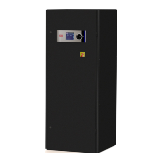
General Design compact 30.6 inches wide by 30.6 inches deep cabinet for The CyberOne EC CW is housed in a steel frame type cabinet units ranging from 12 – 17.5 kW (42 – 60 MBH) and a 48 and is rated for indoor use. The exterior of the cabinet is inches wide by 34 inches deep cabinet for units ranging from coated with a powder coat finish to protect against corrosion. -
Page 8: Figure 1. Typical Cw Internal Layout- Downflow Configuration
CyberOne EC CW IOM Manual SMOKE DETECTOR T/H SENSOR (OPTIONAL) FILTER STEAM FIRESTAT DISTRIBUTOR (OPTIONAL) ELECTRIC BOX AIR PROVING CHILLED WATER DISCONNECT SWITCHES COIL SWITCH (NOTE 1) HOT WATER REHEAT COIL HUMIDIFIER DRAIN PAN HUMIDIFIER CONTROL BOARD ENCLOSURE CONDENSATE PUMP... -
Page 9: Circuit Breakers/Motor Start Protectors
Protectors system. CyberOne EC CW systems incorporate state of the art component protection with the use of motor start protectors Optional Equipment and circuit breakers located in the electric box. If an overload 1.5.1 Heater... -
Page 10: Water Detector
CyberOne EC CW IOM Manual 1.5.4 Water Detector 1.5.5 As an option, STULZ offers spot type or strip/cable type water detectors. Upon sensing a water leak, the water detector control circuit will signal the A/C system controller of the alarm condition. -
Page 11: Installation
Unpack and store these items in a safe place unless you are using them immediately. Moving the Equipment CyberOne EC CW systems are designed to be kept in a Figure 3. Recommended Installation Clearance vertical position. The unit is shipped on a skid to facilitate moving prior to installation. -
Page 12: Conditioned Space
Ceiling R-38 Wall R-21 2.4.1 Floor Mounting The CyberOne EC CW unit uses a frame and panel Floor R-19 construction for unit rigidity and full service accessibility while Door the unit is mounted in place. The vapor barrier is the single most important requirement... -
Page 13: Air Distribution Connection
CyberOne EC CW IOM Manual RETURN RETURN AIR INLET AIR INLET SUPPLY SUPPLY AIR OUTLET AIR OUTLET TOP FREE RETURN TOP DUCTED RETURN Figure 4. Downflow Configuration Typical Air Patterns Air Distribution Connection 2.5.1 Downflow Configuration Air Patterns In a downflow unit, the conditioned supply air discharges through the bottom of the unit, typically into a raised floor. There are two basic return air patterns: top free return and top ducted return (see Figure 4). -
Page 14: Figure 5. Upflow Configuration Typical Air Patterns
CyberOne EC CW IOM Manual TOP DISCHARGE- 2 OR 3-WAY PLENUM BOX SUPPLY SUPPLY AIR OUTLET AIR OUTLET RETURN AIR INLET RETURN AIR INLET FRONT FREE RETURN REAR DUCTED RETURN TOP DUCTED DISCHARGE SUPPLY SUPPLY AIR OUTLET AIR OUTLET RETURN... -
Page 15: Optional Equipment (Field Installed)
CyberOne EC CW IOM Manual Optional Equipment (Field Installed) 2.6.3 Remote Temperature/Humidity Sensor NOTE The remote temperature/humidity (T/H) sensor must be Do not mount any optional equipment on the unit located so that it will properly sense the temperature/ access doors. -
Page 16: Plenum Box Assembly
CyberOne EC CW IOM Manual Spot type water detector 2.7.1 Condensate Drain 2.7.1.1 Gravity Drain Remove the protective cover and connect two control wires to the terminals on the base (terminal A 7/8 inch O.D. copper (sweat type) line is provided to drain lugs are provided). -
Page 17: Humidifier
Utility Connections 2.8.1 Main Power The CyberOne EC CW uses three phase power in a range of voltages. The operating voltage, frequency and phase provided to the unit must match the specifications on the unit nameplate (See Figure 8). The nameplate also provides... -
Page 18: Three-Phase Wiring Connections
2.8.1.1 Three-Phase Wiring Connections Adjusting the capacity potentiometer too high CyberOne EC CW units are designed to have the L1, L2 and may result in the formation of condensate within the system. L3 supply wires connected to corresponding L1, L2 and L3 line terminals on the non-fused service switch. -
Page 19: Start-Up/Commissioning And Unit Shutdown
To perform an emergency shutdown, set the main power 2. Apply power to the CyberOne EC CW system at the main disconnect switch to the Off position. power disconnect switch. Ensure that all blowers and fans are rotating correctly and freely without any unusual noise. -
Page 20: Maintenance
Ensure the drain pan outlet is always free of debris general maintenance inspections. For assistance, contact and the drain pan does not leak. STULZ Product Support. Follow all safety statements while performing any type of maintenance. 4.2.4 Coils Coil(s) should be inspected semi-annually and cleaned WARNINGS as required, following standard coil cleaning practices. -
Page 21: Condensate Pump
CyberOne EC CW IOM Manual 4.2.7 Condensate Pump The condensate pump should be inspected semi-annually and cleaned. Ensure that the float works freely. Wipe the float with a wet cloth and detergent to remove dirt. Clean the tank bottom. Check that the discharge line is open and water can pass through it freely. - Page 22 CyberOne EC CW IOM Manual Symptom Probable Cause Recommendation will automatically reset. Over-temperature of electronics. Over-temperature of motor. After causes 4 and 5 are corrected, the fan(s) must be manually reset by turning off power for 20 seconds. Defective fan.
- Page 23 CyberOne EC CW IOM Manual Symptom Probable Cause Recommendation Control power interrupted Check for loose or broken wires. Water supply has been turned off or is not Connect and/or turn on water supply. connected Humidifier switch is in Off Turn switch to Auto/On position.
-
Page 24: Field Service
CyberOne EC CW IOM Manual Enter the cabinet section that houses the humidifier and Field Service drain the humidifier cylinder by toggling the ON/OFF/ NOTE DRAIN switch on the humidifier to DRAIN. Do not attempt to make repairs without the proper Allow the cylinder to completely drain then turn the hu- tools. -
Page 25: Product Support
Preventive Maintenance Contracts Performance Evaluations The customer is responsible for the shipping cost incurred for returning the defective part(s) back to STULZ. Return of Technician and Owner Training defective part(s) must be within 30 days, at which time an evaluation of the part(s) is conducted and if the part is found Technical Support to have a manufacturing defect a credit will be issued. - Page 26 CyberOne EC CW IOM Manual Maintenance Checklist Prepared by Model Number Title Item Number Date Serial Number Monthly Filters Fans Condensate Drain Fan(s) rotate Cleanliness Drain is open No obstructions Condensate pan safety switch operates freely Additional Check chilled water/hot water circuits for air (bleed as required)
- Page 27 If you need technical support, call 888 529 1266 or email stulztechnicalsupport@stulz- ats.com. Support is available 24/7/365. Provide the model number, serial number, and STULZ item number from the unit nameplate. This will speed up the process and ensure accuracy.
- Page 28 CyberOne EC CW IOM Manual Glossary Term Definition Term Definition American Society of Heating, ASHRAE Refrigerating, and Air-Conditioning Information Technology Engineers Installation, Operation, and BTUH/Hr British Thermal Units Per Hour Maintenance Manual Cubic Feet Per Minute kilowatt CNDCT Conductor Kilo Volt Amps...
- Page 29 North American Headquarters STULZ Air Technology Systems, Inc. 1572 Tilco Drive | Frederick, MD 21704 301.620.2033 | Fax: 301.662.5487 | info@stulz-ats.com Technical Support: 888.529.1266 www.stulz-usa.com OCCO209A Feb 2020 © STULZ Air Technology Systems, Inc. - Specifications subject to change without notice.
Need help?
Do you have a question about the CyberOne EC CW and is the answer not in the manual?
Questions and answers