
Subscribe to Our Youtube Channel
Related Manuals for IBA ibaPADU-8


Summary of Contents for IBA ibaPADU-8
- Page 1 -16/ -32/ -32-R Parallel-Analog-Digital-Converter for 8, 16 or 32 channels Manual Issue 3.3...
- Page 2 Required corrections are contained in the following regulations or can be downloaded on the Internet. The current version is available for download on our web site http://www.iba-ag.com. Protection note Windows® is a label and registered trademark of the Microsoft Corporation. Other pro- duct and company names mentioned in this manual can be labels or registered trade- marks of the corresponding owners.
-
Page 3: Table Of Contents
8.2.5 Service interface (X12) ................... 19 8.2.6 Shield connector(s) for physical earth............. 19 Devices for different analog input physics............20 8.3.1 ibaPADU-8 and ibaPADU-8 High Impedance ..........20 8.3.2 ibaPADU-8 (standard) ..................20 8.3.3 ibaPADU-8- (High Impedance)................ 20 8.3.4 ibaPADU-8-F1 ....................21 8.3.5... - Page 4 Main data or all Device types ................27 10.2 Analog inputs ....................28 10.3 Binary inputs ....................29 10.4 Device data .....................29 10.5 Dimensions drawing ibaPADU-8 ..............30 10.6 Dimensions drawing ibaPADU-16 ..............31 10.7 Dimensions drawing ibaPADU-32 ..............32 10.8 Dimensions drawing ibaPADU-32-R ............... 33 Support and Contact..................34...
-
Page 5: About This Manual
-16/ -32/ -32-R Manual About this manual This manual describes in detail the configuration and use of the products ibaPADU-8/ - 16/ -32/ -32-R. It serves both as a tutorial and a reference document. Target group This manual addresses in particular the qualified professionals who are familiar with handling electrical and electronic modules as well as communication and measurement technology. -
Page 6: Used Symbols
Manual ibaPADU-8/ -16/ -32/ -32-R Used symbols If safety instructions or other notes are used in this manual, they mean: The non-observance of this safety information may result in an imminent risk of death or severe injury: • By an electric shock! •... -
Page 7: Introduction
Digital Units) are designed for data acquisition and control purposes for up to 1 kHz sampling rate. The four basic device types differ only in the amount of signals per de- vice i.e. ibaPADU-8 = 8 analog plus 8 binary inputs. Concerning resolution and accu- racy all devices are similar. -
Page 8: Contents Of Delivery
The following components are part of this delivery: ibaPADU device 115 V/250 V power cord with ibaPADU-16, -32, -32-R 2-pin Phoenix power plug with ibaPADU-8 Manual All necessary Phoenix terminal blocks (spring loaded terminal blocks) for the signal... -
Page 9: System Prerequisites
-16/ -32/ -32-R Manual System prerequisites In order to use the ibaPADU devices for data acquisition you need further components or systems. Hardware IBM-compatible PC with at least one of the following cards: ibaFOB x/4-F (only for ibaPADU devices with S/N <1000) ... -
Page 10: Mounting And Dismounting
Manual ibaPADU-8/ -16/ -32/ -32-R Mounting and Dismounting ibaPADU-8 6.1.1 Mounting Locate the DIN-rail mounting clip on the rear side of the device. Place the device on the DIN rail so that the top part the mounting clip engages the top part of the rail appropri- ately. -
Page 11: System Topologies And Addressing
All ibaPADU devices are normally connected in a straight line topology to their respec- tive ibaFOB-cards. In case of using the external synchronization function (ibaPADU-8 only) the devices are linked in a ring topology. The outputs of the devices are to be connected with the input of the following devices until all devices are interconnected and the last device is connected to the ibaFOB-card. -
Page 12: Examples For Topologies
Manual ibaPADU-8/ -16/ -32/ -32-R Examples for topologies Example 1: Homogeneous ibaPADU-8 chain Up to 8 devices in a line structure. Every device with 8 analog + 8 digital channels must be set to a unique station address between 1...8. - Page 13 -16/ -32/ -32-R Manual Example 3: Mixed chain with ibaPADU-16 and ibaPADU-32 2 devices in a line structure. Device settings are to be set as follows: #1 (occupies 1 and 2) #3 (occupies 3,4,5,6) or #4 (4,5,6,7) or #5 (5,6,7,8) For example: addresses #1 and #4 ibaPADU-16: Addr.
-
Page 14: Product Properties
(ibaLogic) in steps of 100 μs between 1.0 ms and 9.9 ms ibaPADU-8, -16 and -32 are operating in the so called F-Mode, using a data trans- mission rate of 3.3 Mbit/s for fiber optic communication ... -
Page 15: Device, Operating Elements And Connectors
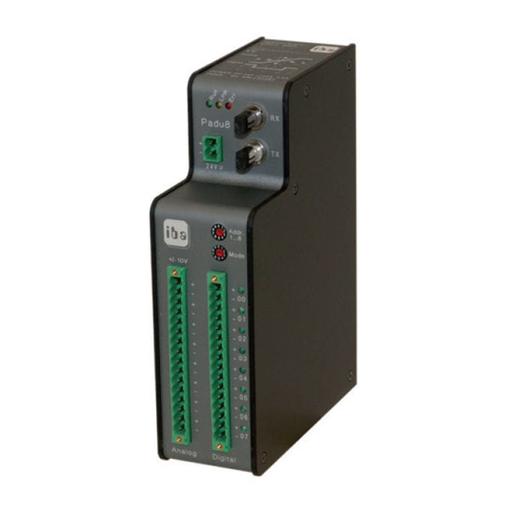
-16/ -32/ -32-R Manual Device, operating elements and connectors 8.2.1 ibaPADU-8 (all types) Front view Top view Serial number and E-Mail address Status LEDs (L1... L3) FO receiver RX (X11) 24V power supply (X14) FO sender TX (X10) Address switch (S1) Mode switch (S2) Analog inputs 00..07... -
Page 16: Ibapadu-16/Ibapadu-32/Ibapadu-32-R
Manual ibaPADU-8/ -16/ -32/ -32-R 8.2.1.2 Fiber optic input X11 (RX) and output X10 (TX) The 2 connectors (ST type) serve to connect the device to the fiber optic bus. The X10 output has all data of the device itself and – in case of a daisy chain – the data from all previous devices. - Page 17 An ibaPADU-16 always needs (occupies) two addresses, an ibaPADU-32 four addresses. Odd addresses are allowed, e. g., if the line begins with a single ibaPADU-8 followed by an ibaPADU-16. Subsequent devices will overwrite data from previous devices if the same address ex- ists multiple times in a chain.
-
Page 18: Run, Link And Error Led Indicators
Manual ibaPADU-8/ -16/ -32/ -32-R 8.2.3 Run, link and error LED indicators Status Indication L1: Run Blinking Power is on and device is ok (green) Insufficient power or device failure L2: Link Data is being received on FO-input (yellow) Blinking No incoming data stream;... -
Page 19: Service Interface (X12)
For loading new firmware from a PC into the device you'll need a standard V.24 interface cable. Note Please contact iba regarding loading new firmware. You will get the required files and further information about the loading procedure. Important note In normal operation mode the V.24-cable must not be connected. -
Page 20: Devices For Different Analog Input Physics
Manual ibaPADU-8/ -16/ -32/ -32-R Devices for different analog input physics 8.3.1 ibaPADU-8 and ibaPADU-8 High Impedance 8.3.2 ibaPADU-8 (standard) 8 analog inputs with ±10 V voltage inputs and R = 100 kΩ (R = device is on) and = 50 kΩ... -
Page 21: Ibapadu-8-F1
= device is on) and = 50 kΩ Low pass filter 250 Hz, 12 dB Figure 9: Simplified input circuitry of ibaPADU-8-F1 (250 Hz, 12 dB) 8.3.5 ibaPADU-8-I = 50 Ω, for current-based signals 8 analog inputs with ±20 mA; R Figure 10: Simplified input circuitry of ibaPADU-8-I (±20 mA) -
Page 22: Configuration/Engineering
The normal simultaneous sampling rate for all devices is 1 Hz. The sampling rate for ibaPADU-8 (only!) may be changed for the devices within one ring topology between 1.0 ms and 9.9 ms in steps of 100 μs with ibaLogic and ibaFOB-io or ibaFOB-4i + ibaFOB-4o or their successors (except ibaFOB-D). - Page 23 Multiple rings can be synchronized by means of an ibaBM-FOX-i-3o device. The first output of an ibaFOB card is multiplied and distributed to the first device of any chain to be synchronized. Set ibaLogic to ibaPADU-8 buffered mode for this operation. Example 5: Externally synchronized operation of multiple ibaPADU-8 chains...
-
Page 24: Accessing Data Of Ibapadu Devices By Software
Manual ibaPADU-8/ -16/ -32/ -32-R Accessing data of ibaPADU devices by software In the following, data access and configuration of ibaPADU connection is shown with ibaPDA as example. The ibaPADU devices can be used together with the following software applications:... -
Page 25: Settings In Ibapda-V6
The devices are connected via ibaFOB-io card, ibaFOB-4i card or ibaCom-PCMCIA-F to the PC. In the I/O-manager dialog, section “Hardware”, you should add an ibaPADU-8, -16 or -32 module to the corresponding FOB-F-PCI… data interface. Figure 13: I/O-Manager, hardware 9.2.1.2... - Page 26 Manual ibaPADU-8/ -16/ -32/ -32-R If the branch with the interface card is marked in the tree on the left side, you can see on the right side the view of the board showing the (four) processors which are assigned to the individual FO links.
-
Page 27: Technical Data
1 g rms 90 Min @ 0 Hz to 250 Hz/axis (all types) 2 g rms 90 Min @ 0 Hz to 250 Hz/axis (all ibaPADU-8 types), ibaPadu-32-R 2 g with ad- ditional rear holder only! EMI test parameters EN 55011 (Class A); EN 61000-4-6 (Class 3);... -
Page 28: Analog Inputs
Manual ibaPADU-8/ -16/ -32/ -32-R Type ibaPADU-8/ ibaPADU-8-HI/ ibaPADU-8-I/ ibaPADU-16/ ibaPADU-32/ -8-F1 /-8-1 -HI-F1/-HI-15/ -8-I-50 -16-HI/-16-F1 -32-HI/-32-HI-60/ -HI-24/-HI-25/ -32-R / -HI-60 -32-R-HI-60 Order no.: 10.120000 (-8) 10.120010 (-HI) 10.120020 (-8-I) 10.121200 (-16) 10.122200 (-32) 10.120001 (-8-F1) 10.120011 (-F1) 10.120021 (-50) 10.121201 (-HI) -
Page 29: Binary Inputs
-16/ -32/ -32-R Manual Type ibaPADU-8/ ibaPADU-8-HI/ ibaPADU-8-I/ ibaPADU-16/ ibaPADU-32/ -8-F1 /-8-1 -HI-F1/-HI-15/ -8-I-50 -16-HI/-16-F1 -32-HI/-32-HI-60/ -HI-24/-HI-25/ -32-R / -HI-60 -32-R-HI-60 10.3 Binary inputs Number Input level ±24 V; U ±60 V; I 1 mA Switching level: log 0; < ±9 V; log 1; > ±10 V;... -
Page 30: Dimensions Drawing Ibapadu-8
Manual ibaPADU-8/ -16/ -32/ -32-R 10.5 Dimensions drawing ibaPADU-8 (Dimensions given in mm) Figure 15: Dimensions drawing ibaPADU-8 Issue 3.3... -
Page 31: Dimensions Drawing Ibapadu-16
-16/ -32/ -32-R Manual 10.6 Dimensions drawing ibaPADU-16 (Dimensions given in mm) Figure 16: Dimensions drawing ibaPADU-16 Issue 3.3... -
Page 32: Dimensions Drawing Ibapadu-32
Manual ibaPADU-8/ -16/ -32/ -32-R 10.7 Dimensions drawing ibaPADU-32 (Dimensions given in mm) Figure 17: Dimensions drawing ibaPADU-32 Issue 3.3... -
Page 33: Dimensions Drawing Ibapadu-32-R
-16/ -32/ -32-R Manual 10.8 Dimensions drawing ibaPADU-32-R (Dimensions given in mm) Figure 18: Dimensions drawing ibaPADU-32-R Issue 3.3... -
Page 34: Support And Contact
Koenigswarterstr. 44 90762 Fuerth Germany Phone: +49 911 97282-0 Fax: +49 911 97282-33 E-Mail: iba@iba-ag.com Contact: Mr. Harald Opel Regional and Worldwide For contact data of your regional iba office or representative please refer to our web site www.iba-ag.com. Issue 3.3...
Need help?
Do you have a question about the ibaPADU-8 and is the answer not in the manual?
Questions and answers