Table of Contents
Advertisement
Advertisement
Table of Contents
Troubleshooting

Related Manuals for Shenzhen Mindray Bio-Medical Electronics PM-8000

Summary of Contents for Shenzhen Mindray Bio-Medical Electronics PM-8000
- Page 1 Service Manual PM-8000 Portable Patient Monitor...
- Page 3 Content of this manual is subject to changes without prior notice. PROPERTY OF ® SHENZHEN MINDRAY BIO-MEDICAL ELECTRONICS CO., LTD. ALL RIGHTS RESERVED Responsibility on the manufacturer party Service Manual of PM-8000 Portable Patient Monitor (V2.0)
- Page 4 Upon request, Mindray may provide, with compensation, necessary circuit diagrams, calibration illustration list and other information to help qualified technician to maintain and repair some parts, which Mindray may define as user serviceable. Service Manual of PM-8000 Portable Patient Monitor (V2.0)
- Page 5 ■ assembly operations, extensions, re-adjusts, modifications or repairs are carried out by persons other than those authorized by Mindray. ■ the PM-8000 Portable Patient Monitor is not used in accordance with the instructions for use, or the electrical installation of the relevant room does not comply with NFPA 70: National Electric...
- Page 6 +86 755 26582680 Fax: Free hot line: +86 800 830 3312 EC Representative Shanghai International Holding Corp. GmbH(Europe) Name: Eiffestrasse 80 D-20537 Hamburg Germany Address: +49 40 2513174 Phone: +49 40 255726 Fax: Service Manual of PM-8000 Portable Patient Monitor (V2.0)
- Page 7 Preface This manual gives detailed description to PM-8000 Portable Patient Monitor concerning its performance, operation, and other safety information. Reading through this manual is the first step for the user to get familiar with the equipment and make the best out of it.
-
Page 9: Table Of Contents
Chapter 3 Checks and Tests........................3-1 I. System checks......................... 3-1 II. Testing and calibrating each parameter..................3-9 Chapter 4 Troubleshooting .........................4-1 I. Disassembly graph of each part of PM-8000................4-1 II. Troubleshooting guidance ......................4-2 Chapter 5 Installation..........................5-1 Unpack inspection......................... 5-1 II. - Page 10 Chapter 8 Maintenance ........................8-1 Chapter 9 Network Link ........................9-1 I. Network performance ......................9-1 II. Application ..........................9-1 Appendix I: System Alarm Prompt....................AI-i Appendix II: Product Specifications....................AII-i 1. Classification...........................AII-i 2. Specifications..........................AII-i Service Manual of PM-8000 Portable Patient Monitor (V2.0)
-
Page 11: Chapter 1 Introduction
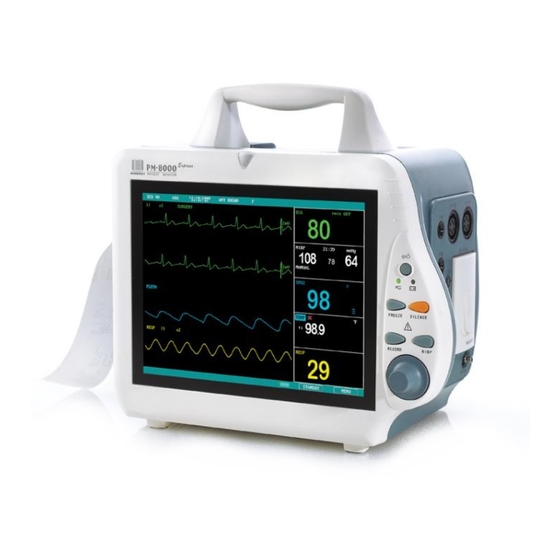
Pmax=100VA FUSE T 1.6A PM-8000 Portable Patient Monitor (Figure 1-1) is adaptable to adult, pediatric and neonatal usage. It can monitor vital signals such as ECG, Respiratory Rate, SpO2, NIBP, TEMP and IBP. It integrates parameter measuring modules, display and recorder into one device, featuring in compactness, lightweight and portability. -
Page 12: Appearance
Figure 1-1 Front view of PM-8000 Portable Patient Monitor 2.1 Screen display The display of PM-8000 may be color or monochrome liquid crystal. (The monitor of PM-8000 is available in both monochrome and color liquid crystal).Patient parameters, waveforms, alarm messages, bed numbers, date, system status and error messages can be displayed on the screen. - Page 13 ” is the sign indicating that the alarm volume is closed. When select the “OFF” option in the ALARM SETUP menu, this mark appears indicating that the operator has permanently closed the Service Manual of PM-8000 Portable Patient Monitor (V2.0)
- Page 14 The waveforms are refreshed in a user-set rate. Refer to the related chapters for details of sweep speed. Parameter Area(③) Parameters are displayed at a fixed position (①~⑩). They are (from top to bottom): Service Manual of PM-8000 Portable Patient Monitor (V2.0)
- Page 15 Blood Pressure: Systolic, Mean, and Diastolic values are displayed from left to right. (⑥, Unit: mmHg or kPa) RESP ⎯ Respiration Rate (⑦, Unit: breath/min) TEMP ⎯ Temperature (⑧, Unit:℃ or ℉) Service Manual of PM-8000 Portable Patient Monitor (V2.0)
-
Page 16: Button Functions
Figure 1-4 PM-8000 Buttons and Knob All the operations of PM-8000 can be performed through using the buttons and the rotary knob at the bottom of the screen. Above the buttons are their respective names. They are (from left to right): Press to turn on/off the monitor. - Page 17 The square frame that moves when the knob is being turned is called "cursor". Operation can be executed at any place where the cursor can stay. When no menu is displayed, turning the knob clockwise can select following hot keys: Service Manual of PM-8000 Portable Patient Monitor (V2.0)
-
Page 18: 2.3 Interfaces
For the convenience of operation, different interfaces are in different parts of the monitor. Recorder is on the left side of the monitor while sockets for patient cables and sensors are on the right side. See the figure below: Figure 1-5 Right side view Service Manual of PM-8000 Portable Patient Monitor (V2.0) - Page 19 Pin 2. Green Video Pin 3. Blue Video Pin 4. Ground Pin 5. Pin 6. Red Ground Pin 7. Green Ground Pin 8. Blue Ground Pin 9. Pin 10. Ground Pin 11. Service Manual of PM-8000 Portable Patient Monitor (V2.0)
-
Page 20: 2.4 Built-In Rechargeable Battery
Plug the cable into proper socket before powering on the VGA monitor. It is allowable to power on the VGA monitor and PM-8000 at the same time. Or power on PM-8000 after turning on VGA monitor. Adjust brightness and contrast properly. -
Page 21: Hardware Principle
If the battery is not installed in PM-8000, battery state will be displayed as “... -
Page 22: 3.1 Power Board
Charging 12V output Managerent circuit Figure 1-9 circuit diagram of PM-8000 power board Testing key points: Connect AC power (at this time, the Charge indicator of the battery should light on). Test before power on the monitor. Use multimeter to measure the DC voltage of the capacitor C12, which should be within the range of 107 ~ 354V. -
Page 23: 3.2 Pm-8000 Main Control Board
5V and 12V stabilized voltage supplies are introduced from the power board, and therefore 3.3V and 2.5V working supplies are respectively generated. Among them, 2.5V is to be used for the internal verification of FPGA. Service Manual of PM-8000 Portable Patient Monitor (V2.0) 1-13... -
Page 24: 3.3 Structure Diagram
It use tow parallel-connected 512Kx16 FLASH memories. The output terminal PP1 of CPU is used to realize write-protection of FLASH. It is effective in low-level state.。 ■ DRAM PM-8000 main control board uses two parallel-connected 1Mx16 DRAM, which construct 4M address space. ■ Display The resolution is 800x600. - Page 25 ■ Network controller The network controller adopts special chip AX88796. Its working clock is 25MHz. It also has internal 16K high-speed buffer SRAM. The data bus of this chip is 16-bit width. Service Manual of PM-8000 Portable Patient Monitor (V2.0) 1-15...
-
Page 26: 3.5 Button Schematic Diagram And Principle
Scanning of buttons and encoder: Determine whether a button or the encoder is pressred through the way of scanning the state of singlechips P1.0~P1.2. Determine whether encoder is turned and its turning direction by scanning the state of P1.4 and P1.5. 3.5.2 Important measurement points 1-16 Service Manual of PM-8000 Portable Patient Monitor (V2.0) -
Page 27: Maintenance Part Of Tr60-A Recorder
CPLD9536 drive board is 5V CMOS. The processor works under 3.3V. The system uses a CPLD X9536XL, by which the output logic of the OC gate is generated, therefore converting 3.3V level into : Test points are listed out in the table below 3.6.6 Service Manual of PM-8000 Portable Patient Monitor (V2.0) 1-17... - Page 28 Thermal head heating and motor power: 8~8.4V U9.2 Logic component power of the drive board: 3.0~3.6V U4.5 Logic power of the thermal head: 4.75~5.25V RESET TP30 CPU reset signal, high level after power-on: (>2.4V)。 1-18 Service Manual of PM-8000 Portable Patient Monitor (V2.0)
-
Page 29: Introduction
Principles I. Introduction PM-8000 portable patient monitor uses parameter module as the basic unit to acquire signals. The results are transmitted to the main control board via keyset to finally process and display the data and waveforms. The commands of the main control board and status messages of modules are transmitted also through the keyset. -
Page 30: Ecg/Resp Parameters
The Monitor measures temperature by measuring the changes in resistance of a thermistor located in the temperature lead. When a person is respiring, his chest goes up and down. This movement equals to Service Manual of PM-8000 Portable Patient Monitor (V2.0) -
Page 31: Nibp
97% .The SpO2 numeric shows the percentage of hemoglobin molecules which have combined with oxygen molecules to form oxyhemoglobin. The SpO2/PLETH parameter can also provide a pulse rate signal and a plethysmogram wave. Arterial oxygen saturation is measured Service Manual of PM-8000 Portable Patient Monitor (V2.0) -
Page 32: Temp
In this way we can at any time obtain the dynamic waveform of the changing pressure inside the vessel. By using specified calculating formula, we can calculate systolic, diastolic and mean pressures. Service Manual of PM-8000 Portable Patient Monitor (V2.0) -
Page 33: Chapter 3 Checks And Tests
Chapter 3 Checks and Tests I. System checks For the conventional testing contents of PM-8000 portable patient monitor, please refer to its Operation Manual. The information in this chapter is only a brief introduction. The following sections are used to emphasize important tests and the information not clearly specified in the Operation Manual. - Page 34 [Leakage] key of the 501 tester. Then press the [neutral] key of the 501 tester, disconnect N line. Respectively press and release the [Polarity] key to toggle between null line and live wire, and imitate the condition that L line is Service Manual of PM-8000 Portable Patient Monitor (V2.0)
- Page 35 (C)-----application part processing kit ① ------device being tested ⑤ ------application part A-------tinsel RED---red measurement clip of 501 SUM---kit post 2.2.2.2 leakage current between the shell to protection earth in the normal state: Service Manual of PM-8000 Portable Patient Monitor (V2.0)
- Page 36 (C). Connect the output SUM of (C0 to the RA post of the 501 tester. Locate all the switches on the connecting kit of the application part to [OFF] position. Service Manual of PM-8000 Portable Patient Monitor (V2.0)
- Page 37 0.05mA. 2.2.3.3.2 Press the [DC Only] key of 501, take turns to operate the [Ground] key (for disconnecting the ground wire), the [Neutral] key (for disconnecting the null Service Manual of PM-8000 Portable Patient Monitor (V2.0)
- Page 38 ① -----device being tested ⑤ -----application part P3----sensors connected to the patient RA----RA terminal of the ECG measuring post of 501 LL----LL terminal of the ECG measuring post of 501 SUM---kit post Service Manual of PM-8000 Portable Patient Monitor (V2.0)
- Page 39 [Neutral] key (for disconnecting the null line) and the [Polarity] key (for toggling between null line and live wire). Test the current in the above three fault conditions, the maximu m current value should be less than 0.05mA. Service Manual of PM-8000 Portable Patient Monitor (V2.0)
- Page 40 25A. Wait for 5 seconds and then read the value on the voltage meter (use AC voltage range of the mu ltimeter), which should be less than 2.5V. Service Manual of PM-8000 Portable Patient Monitor (V2.0)
-
Page 41: Testing And Calibrating Each Parameter
2.5V. II. Testing and calibrating each parameter Testing and calibrating follow parameters are to ensure the accuracy of PM-8000 portable patient monitor. Calibrating operation should be performed at least once a year. Calibration should be carried out each time after maintenance. - Page 42 NM=70 ND=60 ③ Check if the actual measured values of PM-8000 are consistent to those set up on the simulator. ④ Change the setup values on the simulator, and test again. ⑤ Check if the actual measured values are consistent with setup one.
- Page 43 Set up the BP sensitivity of the simulator to 5uv/v/mmHg, and BP to 0mmHg. Set up the name of IBP1 to ART. Access the PRESSURE ZERO option of IBP SETUP MENU of PM-8000, zero Channel 1 to perform zero calibration for IBP. After the zero calibration is successful, exit the menu to enter the main screen.
-
Page 45: Chapter 4 Troubleshooting
Troubleshooting Chapter 4 Troubleshooting I. Disassembly graph of each part of PM-8000 1 Front panel assembly 6 Main bracket assembly 2 Rear panel assembly 7 Cross panhead cuspless screw PT3x10 3 Battery door 8 Cross panhead screw M3x6 4 Sockets cover... -
Page 46: Troubleshooting Guidance
9 NIBP/IBP bracket assembly II. Troubleshooting guidance In transportation, storage and use of PM-8000, various factors such as unstable network voltage, changing environmental temperature, falling-down or impact, component aging may all result in PM-8000 failures and therefore affect normal application of the device. In failure conditions, professional personnel with the experience of repairing electronic medical devices should perform component-level upkeep as per the failure classification listed in the table below. - Page 47 ① connect external VGA display power supply is in normal and confirm the failure operation, however, there is no ② bad connecting wire of ② repair or replace connecting wire display or screen goes black display Service Manual of PM-8000 Portable Patient Monitor (V2.0)
- Page 48 ① replace this part connecting a part. short-circuit. Indicators of power and main ① +12V power control board light ① replace the power however, the fan does not run damaged. Service Manual of PM-8000 Portable Patient Monitor (V2.0)
- Page 49 ① connect TEMP sensor stablely. TEMP value is incorrect poorly connected. ① ECG waveform is not ① Adjust the connection to make the HR value is inaccurate, Arr. analysis good. ECG waveform become normal. Service Manual of PM-8000 Portable Patient Monitor (V2.0)
- Page 50 ②Environment light is very ② Weaken the light intensity in the interference. intensive. environment. ① coloring agent has been ① remove the coloring agent before SpO2 value is inaccurate injected into patient body. perform measurement. Service Manual of PM-8000 Portable Patient Monitor (V2.0)
-
Page 51: Chapter 5 Installation
1)Connect the 3-core power plug into the AC receptacle. 2)Press the power button on the panel of PM-8000, wait for about 10 seconds, the Start-up picture appears on the screen, followed by the displays of waveform scanning lines and data screen. -
Page 53: Chapter 6 Basic Operations
Basic Operations Chapter 6 Basic Operations I. Basic operation guidance On the right side of the front panel of PM-8000, there are following buttons from up to down: 1) POWER Used to turn on/off the PM-8000. 2) FREEZE When in normal mode, press this button to stop waveform refreshing and freeze all the waveforms on the screen. - Page 54 3.Turn on the power switch on the rear panel of the PM-8000. After waiting for about 10 seconds, the screen displays “System is initializing, please wait…”. Wait for about another 12 seconds, monitoring picture and waveform scanning lines appear on the screen.
-
Page 55: Chapter 7 Cleaning And Disinfection
′ Note ′ Please pay special attention to the following items to avoid damaging PM-8000: Avoid using ammonia-based or acetone-based cleaners such as acetone. Most detergents must be diluted before use. Follow the manufacturer's directions carefully for dilution. -
Page 56: Sterilization
■ Alcohol ■ Isopropanol ′ Note ′ PM-8000 monitor and sensor surface can be cleaned with hospital-grade ethanol and dried in air or with crisp and clean cloth. ′ Note ′ Mindray has no responsibility for the effectiveness of controlling infectious disease using these chemical agents. -
Page 57: Precautions And Cleaning
If ECG cable is damaged or aged, replace with a new ECG cable. 1 Cleaning PM-8000 monitor and sensor surface can be cleaned with hospital-grade ethanol and dried in air or with crisp and clean cloth. 2 Sterilization To avoid extended damage to the equipment, sterilization is only recommended when stipulated as necessary in the Hospital Maintenance Schedule. -
Page 58: Ibp Transducer Cleaning And Disinfection(Reusable
V. IBP transducer cleaning and disinfection(reusable) After the IBP monitoring operation is completed, remove the tubing and the dome from the transducer and wipe the transducer diaphragm with water. Soaking and/or wiping with soap can clean the Service Manual of PM-8000 Portable Patient Monitor (V2.0) - Page 59 Follow the operating instructions provided by the manufacturer of the gas disinfectant. Warning The sterilize temperature must not exceed 70°C (150°F). Plastics in the pressure transducer may Service Manual of PM-8000 Portable Patient Monitor (V2.0)
-
Page 60: Temp Sensor Cleaning And Disinfection (Reusable)
This cleaning method can also be applied to the luminotron and receiving unit. 2. The cable can be cleaned with 3% hydrogen dioxide, 70% isopropanol, or other active reagent. However, connector of the sensor shall not be subjected to such solution. Service Manual of PM-8000 Portable Patient Monitor (V2.0) -
Page 61: Chapter 8 Maintenance
PM-8000 portable patient monitor is a type of precision electronic medical device having complex structure. Maintaining PM-8000 carefully will not only let the device develop its performance to the best but also ensure the long-term operating accuracy of the device and avoid various errors. To prevent cross contamination, ensure that the device has undergone cleaning and disinfection before maintenance. -
Page 63: Chapter 9 Network Link
Network Link Chapter 9 Network Link PM-8000 can be connected to Mindray Hypervisor III (type 3000) Central Station to construct monitoring network system. A HyperVisorIII Central Station can connect up to 8 bedside monitors. At the Central Station, the user can view all waveforms and parameters of the networked bedside monitors and modify the alarm setups of the networked bedside monitors as well. -
Page 65: Appendix I: System Alarm Prompt
Check "ASYSTOLE" ASYSTOLE. connection of the electrodes and lead wires. Check the current situation of Patient suffers from Arr. of patient. Check "VFIB/VTAC" VFIB/VTAC. connection of the electrodes and lead wires. Service Manual of PM-8000 Portable Patient Monitor (V2.0) AI-i... - Page 66 The pacemaker is not paced. electrodes and lead wires. Check the current situation of the patient. Check the connection of the No pacemaker signal is pacemaker. "PNC" captured. Check connection electrodes and lead wires. AI -ii Service Manual of PM-8000 Portable Patient Monitor (V2.0)
- Page 67 TEMP sensor Check connection "TEMP SENSOR OFF" connected correctly. TEMP sensor. IBP sensor is not connected Check the connection of IBP "IBP LEAD OFF" correctly. sensor. Service Manual of PM-8000 Portable Patient Monitor (V2.0) AI-iii...
- Page 68 "SYSTEM SOFTWARE ERR" manufacturer. "SYSTEM CMOS FULL" "SYSTEM CMOS ERR" "SYSTEM EPGA FAILURE" "SYSTEM FAILURE2" "SYSTEM FAILURE3" "SYSTEM FAILURE4" "SYSTEM FAILURE5" "SYSTEM FAILURE6" "SYSTEM FAILURE7" AI -iv Service Manual of PM-8000 Portable Patient Monitor (V2.0)
- Page 69 The power part of the prompt appears system has failure. repeatedly, contact "5V TOO LOW" manufacturer for repair. "POWER ERR3" "POWER ERR4" "12V TOO HIGH" "12V TOO LOW" "POWER ERR7" "POWER ERR8" "3.3V TOO HIGH" Service Manual of PM-8000 Portable Patient Monitor (V2.0) AI-v...
- Page 70 If the failure still exists, contact the manufacturer for repair. paper roll Place the paper roll in the "RECORDER PAPER W.P." recorder is not placed in the correct position. AI -vi Service Manual of PM-8000 Portable Patient Monitor (V2.0)
- Page 71 The NIBP communication Execute the reset program in "NIBP COMM ERR" part has problem. the NIBP menu. If the failure Service Manual of PM-8000 Portable Patient Monitor (V2.0) AI-vii...
- Page 72 "PNEUMATIC LEAK" NIBP airway has leaks. If the failure still exists, contact the manufacturer for repair. "MEASURE FAIL" Problem happens when Check the connection of each AI -viii Service Manual of PM-8000 Portable Patient Monitor (V2.0)
- Page 73 Check the connection of each measuring the curve. The part and the patient situation. "NIBP SYSTEM FAILURE" system cannot perform Measure again, if the failure measurement, analysis or still exists, contact calculation. manufacturer for repair. Service Manual of PM-8000 Portable Patient Monitor (V2.0) AI-ix...
-
Page 75: Appendix Ii: Product Specifications
Transport and Storage 10% - 95 %(no coagulate) Altitude Working -500 to 4,600m Transport and Storage -500 to 13,100m Power Supply 100~240 VAC, 50/60 Hz Pmax=100VA FUSE T 1.6A Display Device Service Manual of PM-8000 Portable Patient Monitor (V2.0) AII-i... - Page 76 Operating time after the first alarm of low battery will be about 5 minutes Maximum charging time of single battery is 4 hours. Recorder (Option) Record Width 48 mm Paper Speed 25/50 mm/S Trace Recording types: AII -ii Service Manual of PM-8000 Portable Patient Monitor (V2.0)
- Page 77 ×2.5mm/mV, ×5.0mm/mV, ×10mm/mV, ×20mm/mV, auto Gain HR and Alarm Range Adult 15 ~ 300 bpm Neo/Ped 15 ~ 350 bpm Accuracy ± 1% or ± 1bpm,which great Resolution 1 bpm Sensitivity ≥ 200 uV Service Manual of PM-8000 Portable Patient Monitor (V2.0) AII-iii...
- Page 78 Base line Impedance Range: 200Ω ~2.5 KΩ Bandwidth 0.2 ~ 2.0Hz(-3dB) Resp. Rate Measuring and Alarm Range Adult 0 ~ 120 BrPM Neo/Ped 0 ~ 150 BrPM Resolution 1 rpm AII -iv Service Manual of PM-8000 Portable Patient Monitor (V2.0)
- Page 79 20 ~ 110 mmHg Resolution Pressure 1mmHg Accuracy Pressure ±5mmHg Maximum Mean error ±8mmHg Maximum Standard deviation Overpressure Protection Adult Mode 297±3 mmHg Pediatric Mode 240±3 mmHg Neonatal Mode 147±3 mmHg Service Manual of PM-8000 Portable Patient Monitor (V2.0) AII-v...
- Page 80 Saturation(%SpO2) - During Motion Conditions Adults/ pediatric/ Neonates 70%~100%±3% 0%~69% unspecified Pulse(bpm) - During No Motion Condition 25 to 240 ± 3BPM Pulse(bpm) - During Motion Condition 25 to 240 ± 5BPM Resolution AII -vi Service Manual of PM-8000 Portable Patient Monitor (V2.0)
- Page 81 CVP/RAP/LAP/ICP -10 ~ 40 mmHg P1/P2 -50 ~ 300 mmHg Press Sensor Sensitivity 5 uV/V/mmHg Impedance 300-3000 Ω Resolution 1 mmHg ±2% or ±1mmHg, which great Accuracy Actualization interval about 1s Service Manual of PM-8000 Portable Patient Monitor (V2.0) AII-vii...
- Page 83 P/N:8000-20-10282...
Need help?
Do you have a question about the PM-8000 and is the answer not in the manual?
Questions and answers