Table of Contents
Advertisement
Advertisement
Table of Contents

Subscribe to Our Youtube Channel
Related Manuals for ESP Safety SGOES

Summary of Contents for ESP Safety SGOES
- Page 1 SGOES Infrared Hydrocarbon Gas Detector Operating Manual 820-0006...
- Page 2 SGOES Infrared Hydrocarbon Gas Detector Operating Manual 820-0006 ESP Safety, Inc. 555 North First Street San Jose, CA 95112 USA 408-886-9746 Revision History: 820-0006 Date Revision Description Approved 03/20/14 Reformat 03/24/14 Update for clarity 10/08/18 Terminal Labels...
-
Page 3: Table Of Contents
Earth Grounding ..................................13 General Wiring Requirements ..............................14 SGOES Wiring Terminal Labels ..............................14 Power Up and Stand Alone Operation of SGOES ........................16 5.0 Calibration Procedures ..............................17 SGOES Calibration Using ESP Commander ..........................17 SGOES Calibration Using a HART Communicator ........................19 SGOES Calibration Using Magnetic Wand .......................... - Page 4 Appendix 2: Gas Measurement Range ............................28 Appendix 3: Gas Flash Point Temperatures ..........................29 Appendix 4: SGOES Terminal Block & Wiring for 3-wire and 4-wire Systems ................30 Appendix 5: Maximum Cable Lengths for Analog Connection (using 24VDC Supply) ...............31 Appendix 6: HART Menu Tree ..............................32 Appendix 7: SGOES to Vector FCU ............................33...
-
Page 5: Introduction
(LEL) in air. As determined by application requirements, the SGOES is factory calibrated with one of eight hydrocarbon-based gases (typically methane or propane). Conversion factors are used to correct for gases other than the factory calibration gas. -
Page 6: Principles Of Operation
SGOES Infrared Combustible Gas Detector 820-0006 Operating Manual Principles of Operation Operation is based on selective signal disruption by hydrocarbon molecules. An infrared light source is reflected to a set of optical detectors that simultaneously monitors the infrared power at multiple wavelengths of the infrared spectrum. If no gas is present, the photodetectors will receive all of the power radiated by the IR source. -
Page 7: Sgoes Components
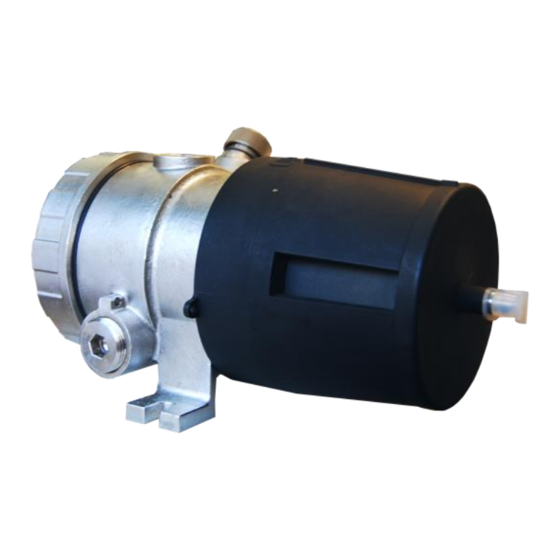
SGOES Infrared Combustible Gas Detector 820-0006 Operating Manual SGOES Components Explosion proof housing Conduit entry for Field Wiring (3/4” NPT), x2 Tri-color LED Status Indicator HART communication port (3/4” NPT), x1 Gas detection chamber Integral mounting lugs Magnetic Calibration Point... -
Page 8: Specifications & Technical Data
SGOES Infrared Combustible Gas Detector 820-0006 Operating Manual 2.0 Specifications and Technical Data Mechanical Characteristics Material Stainless Steel (Type 316) ¾” NPT Conduit Connection 2 connections for Field Wiring 1 connection for HART/USB Dimensions 8.01” x 5.30” x 5.12” (203.5mm x 134.50mm x 130mm) Weight (no sensors) 14.33lb (6.5 kg) -
Page 9: Ordering Guide
SGOES Infrared Combustible Gas Detector 820-0006 Operating Manual Ordering Guide For simplicity of ordering, the SGOES is factory configured for detection specific gases. For gases not included in the table below, please contact ESP Safety. Scale Range %vol IEC6007920- SGOES Model to... -
Page 10: Certifications And Compliance
SGOES Infrared Combustible Gas Detector 820-0006 Operating Manual Certifications and Compliance Explosion-proof for Class 1, Div.1, Group B, C, D (T4) Hazardous (classified) locations per FM 3615, 6310 Dust ignition-proof for Class II, Div.1, Group E, F, G Hazardous (classified) locations per FM 3615, 6310 Non-incendiary for Class 1, Div.2, Group A, B, C, D (T4), Class 2, Div.2, Group E, F, G (T4) Hazardous... -
Page 11: Protective Weather Cover
Cabling entering into and out of the SGOES must utilize connections certified for the hazardous location where the SGOES unit is installed. The cable gland should be able to withstand the pressure of an explosion and prevent the spread of combustion into the hazardous area. -
Page 12: Installation
• The nameplates and warning labels are in place. • The external surfaces and joined surfaces of the SGOES casing are free of dents or damage. • Make sure all removable parts are joined to the casing as tightly as possible. -
Page 13: Mounting
Leak sources include flanges, valves, tubing and connections of the sealed type where seals Sources may either fail or wear. All potential leak sources and SGOES mounting locations are best determined by facility engineers with experience in similar processes. Ventilation &... -
Page 14: Earth Grounding
An earth/ground point is provided on the outside of the VECTOR Field Control Unit Explosion Proof enclosure. The SGOES must be earth grounded in order to operate properly. The grounding lug is located on the SGOES housing below the HART port. -
Page 15: General Wiring Requirements
If installing connection cables in an explosion proof conduit, do not use the same conduit to carry wiring for any other purpose or equipment. • If installing the SGOES in a hazardous area, armored cabling is required for the connections to the SGOES •... - Page 16 Caution: All cable/conduit entries must be sealed with an appropriate and certified sealing plug and cable gland. The use of industrial grade, armored field cable is recommended. If installing the SGOES in a hazardous area, armored cabling is required. Page 15...
-
Page 17: Power Up And Stand Alone Operation Of Sgoes
Verify that the enclosure has been connected to an earth/ground. • If using a SGOES in conjunction with a Field Control Unit such as the SSS- 903 or VECTOR, verify that the connections between the SGOES and the Field Control Unit is secure and functional. -
Page 18: Calibration Procedures
Commander Figure 5-1: Main ESP Commander Form On the Devices list of the main ESP Commander form, double click on the sensor to be calibrated (in this case, the SGOES). This will open the form for the selected sensor. Figure 5-2: SGOES Form Note the calibrate panel in the upper left quadrant of the form. - Page 19 SGOES Infrared Combustible Gas Detector 820-0006 Operating Manual 3) SET ZERO 6) NUMBER OF SPAN GASES 2) SPAN CON 4) SET SPAN 1) MID-SPAN 5) SET MID- CONC. SPAN 7) SELECT/ DESELECT Figure 5-3: SGOES Calibrate Panel Step 1 Step 2 Press the (7) Select/DeSelect button to start the Attach a zero gas to the sensor.
-
Page 20: Sgoes Calibration Using A Hart Communicator
SGOES Infrared Combustible Gas Detector 820-0006 Operating Manual SGOES Calibration using a The following table shows the display menu tree for HART calibration of the SGOES HART Communicator Page 19... -
Page 21: Sgoes Calibration Using Magnetic Wand
Magnetic field calibration can only be performed with the same calibration gas (type and concentration) used to establish the factory settings for the detector. Standard gases used to establish factory setting for the SGOES detectors are methane and propane. Prior to magnetic field calibration, determine the proper calibration gas and concentration. - Page 22 Apply the magnetic wand to the ESP logo and remove. The LED status light will appear SOLID GREEN. This indicates that the SGOES detector is now in operational mode and that the output signals are enabled. Replace the weatherproof protective cover on the detector.
-
Page 23: Troubleshooting
The SGOES does not contain any user-serviceable parts. Any repair of the SGOES should be performed by ESP Safety personnel. Any attempt to repair or service the SGOES by unauthorized personnel will void the product warranty. Page 22... -
Page 24: Maintenance
• Performance test. Maintenance Activities The SGOES needs very little routine maintenance; but periodic checks for proper system function and calibration are strongly advised. The frequency of these checks should be determined by the specific installation. Although the fault-detection circuitry continuously monitors for various problems, it does not monitor external response equipment or wiring. -
Page 25: Warranties
8.0 Warranties ESP Safety, Inc. (“ESP”) warrants the SGOES to be free from defects in material and workmanship under normal use and service for a period of five (5) years, beginning on the date of shipment to the buyer. This warranty extends only to the sale of new and unused products to the original buyer. -
Page 26: Repair And Return
Section 8.0 Troubleshooting of this manual. Please return the device to the factory for repair or replacement. Return Material Contact ESP Safety Inc. at +1-408-886-9746 to obtain a Return Material Authorization Authorization (RMA) (RMA) n umber. Please provide the following information during your call:... -
Page 27: Parts Ordering Information
SGOES Infrared Combustible Gas Detector 820-0006 Operating Manual 10.0 Parts Ordering Information The following items for the SGOES may be ordered: Accessories: Calibration Magnet (magnetic wand), P/N 611-0005 Calibration Cup Replacement Weather Protective Cover HART connection cable RS-485 converter For items not listed above, please contact ESP Safety. -
Page 28: Appendix 1: Calculating Values
Calculation of absolute error The absolute error is calculated using the formula: Са= Сi-Сt Сi – indicated concentration—value reported by SGOES in %vol or %LEL. Сt– known trueconcentration of gas used for calibration in %vol or % LEL Example Using a calibration gas mixture labeled 61.7 LEL. -
Page 29: Appendix 2: Gas Measurement Range
SGOES Infrared Combustible Gas Detector 820-0006 Operating Manual Appendix 2 – Gas Measurement Scale Range Scale Range Limits of Basic Absolute Error Detected %vol %vol SGOES Model %LEL Absolute Relative Hydrocarbon 100-0001- 0 to ± 3% ± 5% Methane 0 to 5 0 to 4.4... -
Page 30: Appendix 3: Gas Flash Point Temperatures
SGOES Infrared Combustible Gas Detector 820-0006 Operating Manual Appendix 3 – Gas Flash Point Temperatures Boiling/Vapor Point at Detected Hydrocarbon Flash Point 1 atmosphere Methane -165 Propane Butane -0.5 -108 Isobutane Pentane Cyclopentane n-Hexane Propylene/Propene Methanol Ethanol 78 °C Page 29... -
Page 31: Appendix 4: Sgoes Terminal Block & Wiring For 3-Wire And 4-Wire Systems
SGOES Infrared Combustible Gas Detector 820-0006 Operating Manual Appendix 4 – SGOES Terminal Block & Wiring for 3-Wire and 4-Wire Systems SGOES Terminal Block Page 30... -
Page 32: Appendix 5: Maximum Cable Lengths For Analog Connection (Using 24Vdc Supply)
SGOES Infrared Combustible Gas Detector 820-0006 Operating Manual Appendix 5 – Maximum Cable Lengths for Analog Connection (using 24VDC Supply) Wire Ohms Ohms Gauge Per Foot Feet Per Meter Meters 22AWG .016 2460 .053 .33mm 20AWG .010 3936 .033 1200 .52mm... -
Page 33: Appendix 6: Hart Menu Tree
SGOES Infrared Combustible Gas Detector 820-0006 Operating Manual Appendix 6: HART Menu Tree Page 32... -
Page 34: Appendix 7: Sgoes To Vector Fcu
SGOES Infrared Combustible Gas Detector 820-0006 Operating Manual Appendix 7: SGOES to VECTOR FCU Page 33... -
Page 35: Appendix 8: Sgoes To Upes
SGOES Infrared Combustible Gas Detector 820-0006 Operating Manual Appendix 8: SGOES to UPES Page 34... -
Page 36: Appendix 9: Sgoes To Analog Input Module
SGOES Infrared Combustible Gas Detector 820-0006 Operating Manual Appendix 9: SGOES to Analog Input Module Page 35...
Need help?
Do you have a question about the SGOES and is the answer not in the manual?
Questions and answers