
Subscribe to Our Youtube Channel
Related Manuals for NXP Semiconductors FRDM-HB2001-EVM


Summary of Contents for NXP Semiconductors FRDM-HB2001-EVM
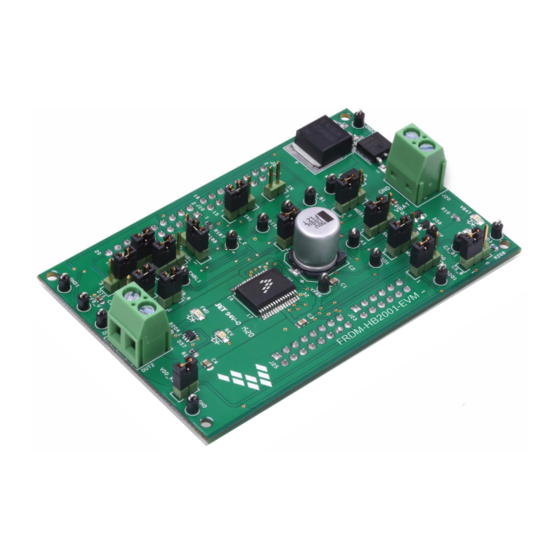
- Page 1 NXP Semiconductors Document Number: KTFRDMHB2001EVMUG User’s guide Rev. 1.0, 2/2016 FRDM-HB2001-EVM evaluation board Figure 1. FRDM-HB2001-EVM © 2016 NXP B.V.
-
Page 2: Table Of Contents
11 Revision history ..................30 FRDM-HB2001-EVM evaluation board, Rev. -
Page 3: Important Notice
NXP was negligent regarding the design or manufacture of the part. NXP™ and the NXP logo are trademarks of NXP Semiconductor, Inc. All other product or service names are the property of their respective owners. © 2016 NXP B.V. FRDM-HB2001-EVM evaluation board, Rev. 1.0 NXP Semiconductors... -
Page 4: Getting Started
Getting started Getting started Kit contents/packing list The FRDM-HB2001-EVM contents includes: • Assembled and tested evaluation board/module in anti-static bag • FRDM-KL25Z • Warranty card Jump start NXP’s analog product development boards help to easily evaluate NXP products. These tools support analog mixed signal and power solutions including monolithic ICs using proven high-volume SMARTMOS mixed signal technology, and system-in-package devices utilizing power, SMARTMOS and MCU dies. -
Page 5: Getting To Know The Hardware
Board overview The FRDM-HB2001-EVM evaluation kit exercises all the functions of the MC33HB2001 H-Bridge device. The parallel input can be easily controlled by lab equipment or any MCU with GPIOs. The board can be used in conjunction with a FRDM-KL25Z board connected to a PC’s USB port. - Page 6 • Internal protection for overtemperature, undervoltage and short-circuit by signaling the er- ror condition and disabling the outputs • I/0 Pins can withstand up to 36 V 3.3.2 Modes of operation Figure 3. Modes of operation FRDM-HB2001-EVM evaluation board, Rev. 1.0 NXP Semiconductors...
- Page 7 Getting to know the hardware 3.3.3 Architecture Figure 4. Architecture 3.3.4 Thermal management Figure 5. Architecture FRDM-HB2001-EVM evaluation board, Rev. 1.0 NXP Semiconductors...
- Page 8 Getting to know the hardware Board description Figure 6 describes the main elements on the FRDM-HB2001-EVM. 5.0 V Regulator Jumpers Test Points Reverse Battery Protection Power and Output Ground Terminal Inputs MC33HB2001 Figure 6. Board description Table 2. Board Description...
- Page 9 GREEN LED, indicates when +5.0 V supply is connected FS_B RED LED, illuminates when the H-Bridge detects a fault GREEN LED, indicates current flowing in forward direction RED LED, indicates current flowing in reverse direction FRDM-HB2001-EVM evaluation board, Rev. 1.0 NXP Semiconductors...
- Page 10 MISO control through MCU SPI output J10 Pin 10 (SPI_MISO) MISO 2–3 MISO not connected for operation without SPI CFB connected to 200 resistor 1–2 VDD connected to VDDQ VDDQ 2–3 VDDQ not connected FRDM-HB2001-EVM evaluation board, Rev. 1.0 NXP Semiconductors...
- Page 11 Output signal definitions The FRDM-HB2001-EVM uses the following output signals to drive a load such as a brushed DC motor. The board provides an analog output for real time load current monitoring. This signal allows closed loop control of the load.
- Page 12 Chip select bar SCLK SCLK1 Clock for SPI MOSI MOSI1 Master output slave input signal MISO MISO1 Master input slave output signal Ground signal GND1 Ground signal GND2 Ground signal GND3 Ground signal FRDM-HB2001-EVM evaluation board, Rev. 1.0 NXP Semiconductors...
- Page 13 The board has the following screw terminal connections to connect the power supply and the load. Figure 10. Screw terminal locations Table 8. Screw Terminal Connections Screw Terminal Name Description Power supply connector for the MC33HB2001 Output connector to connect load FRDM-HB2001-EVM evaluation board, Rev. 1.0 NXP Semiconductors...
-
Page 14: Frdm-Kl25Z Freedom Spi Dongle
GPIOs and SPI pins. The FRDM-KL25Z also monitors the SPI registers, thereby facilitating the use of safety and advanced diagnostic functions. The FRDM-HB2001-EVM connects to the FRDM-KL25Z using the four dual row Arduino™ R3 connectors on the bottom of the board (see Table... - Page 15 FRDM-KL25Z Freedom SPI dongle Figure 12. Connecting the FRDM-HB2001-EVM to the FRDM-KL25Z Figure 13. FRDM-KL25Z to FRDM-HB2001-EVM connections FRDM-HB2001-EVM evaluation board, Rev. 1.0 NXP Semiconductors...
- Page 16 FRDM-KL25Z Freedom SPI dongle Table 9. FRDM-HB2001-EVM to FRDM-KL25Z Connections FRDM-HB2001-EVM FRDM-KL25Z Pin Hardware Name Description Header Header FRDM-HB2001-EVM FRDM-KL25Z PTC7 No Connection PTA1 No Connection PTC0 No Connection PTA2 No Connection PTC3 No Connection PTD4 No Connection PTC4 No Connection...
- Page 17 FRDM-KL25Z Freedom SPI dongle Table 9. FRDM-HB2001-EVM to FRDM-KL25Z Connections (continued) FRDM-HB2001-EVM FRDM-KL25Z Pin Hardware Name Description Header Header FRDM-HB2001-EVM FRDM-KL25Z PTD7 No Connection FRDM_VDD PTE1 No Connection PTE20 No Connection PTB0 No Connection PTE21 No Connection PTB1 No Connection...
-
Page 18: Installing The Software And Setting Up The Hardware
Installing the software and setting up the hardware Configuring the hardware The FRDM-HB2001-EVM consists of an H-Bridge, a parallel and SPI interface, power conditioning circuitry and an FRDM-KL25Z board. The board can be configured for use in conjunction with a FRDM-KL25Z board or a function generator. - Page 19 5.1.2 Step-by-step instructions for setting up the hardware for use with a function generator This section describes how to configure the FRDM-HB2001-EVM for use with a function generator. The same connections apply if the board is connected to a microcontroller instead of a function generator. See the board description (Section 3.4, Board description, page...
- Page 20 To access the HB2000/HB2001 tab in the SPIGen window, expand the HB2000/HB2001 folder in the Device View. Then click on the Registers icon (see Figure 17). If the pre-programmed code on FRDM-KL25Z is accidentally erased, download "UsbSpiDongleKL25Z_SPIDrive_v512.srec" from the following link: www.nxp.com/Usb-Spi-Dongle-firmware-KL25Z-HB2000-1. FRDM-HB2001-EVM evaluation board, Rev. 1.0 NXP Semiconductors...
- Page 21 Installing the software and setting up the hardware Figure 17. MC33HB2001 SPI window Reading all the SPI Registers displays the following default status. Figure 18. SPI control FRDM-HB2001-EVM evaluation board, Rev. 1.0 NXP Semiconductors...
- Page 22 This section is designed for ease of use. Each dropdown menu sets or resets appropriate bits in the registers for a selected configuration. However, after configuration selection, press the write button of the corresponding register to be able to SPI Control configure the part. FRDM-HB2001-EVM evaluation board, Rev. 1.0 NXP Semiconductors...
- Page 23 • After selection of parallel control configuration, press “Start” to activate the outputs Stop: • Press “Stop” to deactivate the outputs Current Feedback: • Shows current through the high-side FET using the current recopy feature Status Fault: • Shows any fault condition in Sleep mode FRDM-HB2001-EVM evaluation board, Rev. 1.0 NXP Semiconductors...
- Page 24 Forward - High-side Recirculation IN1 = 1, IN2 = PWM signal with selected duty cycle and frequency Reverse - High-side Recirculation IN1 = 0, IN2 = PWM signal with selected duty cycle and frequency FRDM-HB2001-EVM evaluation board, Rev. 1.0 NXP Semiconductors...
-
Page 25: Schematic
Schematic Schematic Figure 21. Evaluation Board Schematic FRDM-HB2001-EVM evaluation board, Rev. 1.0 NXP Semiconductors... -
Page 26: Board Layout
Board layout Board layout Silkscreen FRDM-HB2001-EVM evaluation board, Rev. 1.0 NXP Semiconductors... -
Page 27: Board Bill Of Materials
RES MF 200 1/10 W 1% 0603 R202 RK73H1JTTD2000F R203, R204 1.0 K RES MF 1.0 K 1/10 W 1% 0603 AR03FTNX1001 R206, R207, R208, R209 4.70 K RES MF 4.70 K 1/10 W 1% 0603 RK73H1JTTD4701F FRDM-HB2001-EVM evaluation board, Rev. 1.0 NXP Semiconductors... -
Page 28: Accessory Item Bill Of Materials
NXP does not assume liability, endorse, or warrant components from external manufacturers are referenced in circuit drawings or tables. While NXP offers component recommendations in this configuration, it is the customer’s responsibility to validate their application. FRDM-HB2001-EVM evaluation board, Rev. 1.0... -
Page 29: References
FRDM-KL25Z Tool Summary Page www.nxp.com/SPIGEN SPIGen Software 10.1 Support Visit www.nxp.com/support for a list of phone numbers within your region. 10.2 Warranty Visit www.nxp.com/warranty to submit a request for tool warranty. FRDM-HB2001-EVM evaluation board, Rev. 1.0 NXP Semiconductors... -
Page 30: Revision History
Revision history Revision history Revision Date Description of Changes 2/2016 • Initial release FRDM-HB2001-EVM evaluation board, Rev. 1.0 NXP Semiconductors... - Page 31 How to Reach Us: Information in this document is provided solely to enable system and software implementers to use NXP products. There are no expressed or implied copyright licenses granted hereunder to design or fabricate any integrated circuits Home Page: based on the information in this document.
Need help?
Do you have a question about the FRDM-HB2001-EVM and is the answer not in the manual?
Questions and answers