Advertisement
Quick Links
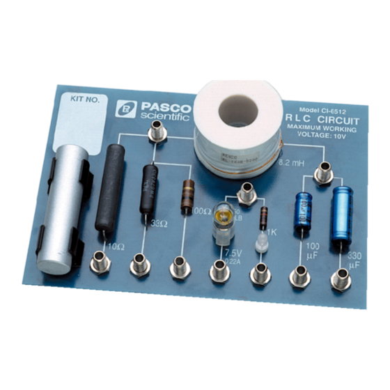
Inductor
1
An air core inductor with an inductance of
8.2 mH.
Steel Rod
2
For placing inside the inductor to increase the
inductance.
Resistors
3
Includes three resistors with a resistance of
100 Ω, 33 Ω, and 10 Ω.
Introduction
The RLC Circuit board is designed to be used with a PASCO
850 or 550 Universal Interface to study the behavior of
resistors, inductors, and capacitors in an AC circuit. The board
includes three resistors, two capacitors, an air-core inductor, a
#50 miniature screw lamp, and a bi-color LED. The included
RLC Circuit
Lamp
4
A replaceable #50 miniature screw base lamp.
LED
5
A bi-color LED in series with a 150 Ω resistor.
The illuminated color is dependent on the
polarity of the connection.
Capacitors
6
Includes two electrolytic capacitors with a
capacitance of 330 µF and 100 µF.
steel rod can be used to increase the inductance of the inductor
by placing the rod inside the coil.
NOTE: Prior to the first use, remove the bolt that secures
the inductor during shipping.
012-04818E
CI-6512 RLC Circuit Product Manual
Page 1 of 4
Advertisement

Subscribe to Our Youtube Channel
Related Manuals for PASCO CI-6512


Summary of Contents for PASCO CI-6512
- Page 1 Introduction by placing the rod inside the coil. The RLC Circuit board is designed to be used with a PASCO NOTE: Prior to the first use, remove the bolt that secures 850 or 550 Universal Interface to study the behavior of the inductor during shipping.
- Page 2 2. Connect the signal generator port to the banana jack of a PASCO Data Collection Software PASCO Capstone or SPARKvue software is required for capacitor. data collection and to control the signal output of the 3.
- Page 3 CI-6512 RLC Circuit Product Manual LR Circuit Setup Each resistor is connected in series with the inductor on the RLC Circuit board. To create an LR circuit: 1. Connect the ground port of the signal generator to the banana jack of a resistor.
- Page 4 PASCO scientific, is prohibited. Trademarks: PASCO and PASCO scientific are trademarks or registered trademarks of PASCO scientific, in the United States and/or in other countries. All other brands, products, or service names are or may be trademarks or service marks of, and are used to identify, products or services of, their respective owners.
Need help?
Do you have a question about the CI-6512 and is the answer not in the manual?
Questions and answers