
Related Manuals for dallmeier DDF4900HDV Series


Summary of Contents for dallmeier DDF4900HDV Series
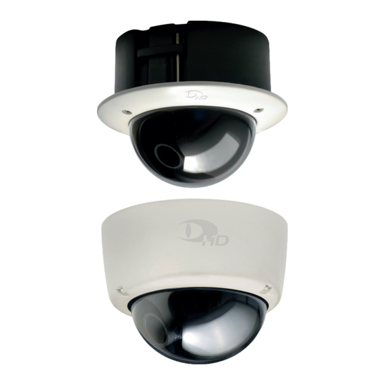
- Page 1 Installation and Configuration English Vandal-resistant High Definition IP Dome Camera DDF4900HDV 1080p DDF4500HDV 720p (In-ceiling Mount Variant) (Surface Mount Variant) Rev. 1.0.3 / 2010-10-27...
- Page 2 Third-party trademarks are named for information purposes only. Dallmeier electronic respects the intellectual property of third parties and always attempts to ensure the complete identification of third-party trademarks and indication of the respective holder of rights. In case that protected rights are not indicated separately, this circumstance is no reason to assume that the respective trademark is unprotected.
-
Page 3: Table Of Contents
Time Server ....................29 Camera Name....................30 User Management ..................30 8.4.1 Login Mode ....................30 8.4.2 User Groups....................31 8.4.3 User ......................32 8.4.3.1 Define a User ....................32 8.4.3.2 Edit User .......................33 8.4.4 Rights ......................33 9 Network ......................35 Basic Settings ....................35 9.1.1 Manual Configuration ..................36 www.dallmeier.com... - Page 4 Info ........................61 13 Image Transmission ...................62 13.1 Web Browser ....................62 13.2 RTSP Application ..................62 14 Maintenance ....................64 15 Pin Assignment ...................65 15.1 DC Auto Iris Interface ..................65 15.2 LAN/PoE .......................65 15.3 Audio OUT ....................66 15.4 Power IN .......................66 16 Technical Data .....................67 www.dallmeier.com...
- Page 5 DDF4900HDV / DDF4500HDV 17 Technical Drawings ..................69 17.1 In-ceiling Mount Variant ................69 17.2 Surface Mount Variant ..................70 www.dallmeier.com...
-
Page 6: Introduction
The document entitled “Installation and Configuration” contains detailed descriptions of the installation, connection, commissioning and configuration of the device. Safety instruc- tions, general notes and technical data are additionally provided. The target audience is exclusively specially trained and authorized professionals (install- ers). www.dallmeier.com... -
Page 7: Conventions
Expressions in bold/italics generally indicate a control element on the device (switches or labels) or on its user interface (buttons, menu entries). Paragraphs in italics provide information on basic principles, special features and efficient procedure as well as general recommendations. www.dallmeier.com... -
Page 8: Safety Instructions
System components Only use internal components that have been tested and approved by Dallmeier. Inappro- priate internal components can cause malfunctions, damages and data loss and can result in loss of warranty. - Page 9 The housing of the unit may only be opened by qualified personnel for commissioning, inspection, maintenance and repair. Disposal Disconnect the unit from the power supply. Remove all connected devices. Return the unit to your respective sales partner. www.dallmeier.com...
-
Page 10: General Notes
3.2 Transportation and Packaging Store the original packaging for transportation at a later date. Dallmeier electronic is not responsible for damage resulting from unprofessional/improper transportation. The goods should only be shipped in their original packaging. If the original packaging is no longer available, ensure that the packaging used sufficiently protects the unit against damage, moisture, heat and cold. -
Page 11: Warranty
3.5 Warranty The terms and conditions valid at the signing of the contract shall apply. 3.6 Approvals/Certifications Following approvals/certifications were valid at the time of document compilation. Refer to www.dallmeier.com for possible updates. • CE • DIN 50130-4 compliant www.dallmeier.com... -
Page 12: Requirements
• The quality of the video image depends on the lens, the lighting and the used moni- tor. • Automatic white balance depends on the lighting used and can cause colour distor- tions in artificial light. • Poor lighting can lead to faulty white balance. www.dallmeier.com... -
Page 13: Views And Connection Assignment
DDF4900HDV / DDF4500HDV 5 Views and Connection Assignment 5.1 In-ceiling Mount Variant Thread for PG16 cable gland Thread for M6 screw eye bolt Housing Ceiling clamp 3-axis mount (pan / tilt / rotation) Lens Trim ring with bubble Housing screw (T20 Torx) Fig. 5-1 www.dallmeier.com... - Page 14 Video preview output Thread for (BNC, CVBS) housing screw Locking screw Locking screw (focal length) (focus) Cable fastener Cable fastener M4 locking screw Thread for (ceiling clamp) housing screw Thread for PG16 cable gland Fig. 5-2 Housing (top view) www.dallmeier.com...
-
Page 15: Surface Mount Variant
DDF4900HDV / DDF4500HDV 5.2 Surface Mount Variant Mounting hole for Ø 4 mm screw Housing base Thread for PG16 cable gland 3-axis mount (pan / tilt / rotation) Lens Housing with bubble Housing screw (T20 Torx) Fig. 5-3 www.dallmeier.com... - Page 16 Ø 4 mm screw Locking screw (focal length) Locking screw (focus) Thread for Thread for housing screw housing screw Cable fastener Cable fastener Mounting hole for Ø 4 mm screw Thread for PG16 cable gland Fig. 5-4 Housing base (top view) www.dallmeier.com...
-
Page 17: Camera Module
Locking screw (rotation, z-axis) DC auto iris interface for iris control Audio OUT SDHC card* LAN / PoE Power IN (3.5 mm phone jack) (RJ45 jack) (12 V DC) *Not included in the standard scope of delivery. Fig. 5-5 www.dallmeier.com... -
Page 18: Installation And Commissioning
In order to comply with the UL requirements, you have to use a UL-certified, limited power source (LPS) Class 2 power supply unit. 6.1 In-ceiling Mount Variant You need: • Drywall utility saw or jigsaw • M6 screw eye bolt • T20 torx wrench • Ceiling hook • Safety wire • Carabiner • Phillips screwdriver (M4) www.dallmeier.com... - Page 19 Unscrew the 3 housing screws using a T20 torx wrench and remove the trim ring. Ø 143 mm Suspended ceiling M6 screw eye bolt PG16 cable gland Ceiling clamp Trim ring with bubble Housing screw (T20 Torx) Fig. 6-1 www.dallmeier.com...
- Page 20 Screw the PG16 cable gland in the appropriate thread of the housing. Insert the housing into the circular recess. Supporting structure Ceiling hook Safety wire PG16 cable gland Carabiner M6 screw eye bolt Ceiling clamp Suspended ceiling Fig. 6-2 www.dallmeier.com...
- Page 21 Tighten the M4 locking screw (Fig. 5-2) of both ceiling clamps with a Phillips screw- driver until the housing is fixed (Fig. 6-4). Ceiling clamp Ceiling clamp Suspended ceiling Phillips screwdriver Fig. 6-3 Locked ceiling clamp Locked ceiling clamp Suspended ceiling Fig. 6-4 www.dallmeier.com...
- Page 22 Disconnect the CVBS monitor. Attach the trim ring to the housing and tighten the 3 housing screws using a T20 torx wrench. Locked ceiling clamp Locked ceiling clamp Suspended ceiling Trim ring with bubble Housing screw (T20 Torx) Fig. 6-5 www.dallmeier.com...
-
Page 23: Surface Mount Variant
Adjust the lens direction using the 3-axis mount and set the focal length and focus. Disconnect the CVBS monitor. Attach the housing to the housing base and tighten the 3 housing screws (Fig. 5-3) us- ing a T20 torx wrench. www.dallmeier.com... -
Page 24: Connection And Login
• a more powerful PC is required if several devices are configured with live video display simultaneously. • a DirectX compatible graphics card and the Dallmeier control for ActiveX are not re- quired for the configuration without live video display. - Page 25 Activate the Networks with routers (NAt) checkbox if required. Adjust the live video resolution (D) if required. This resolution setting only affects the live video display in the web browser and is not re- lated to the encoder settings. www.dallmeier.com...
-
Page 26: Login
Change the factory default password as soon as possible. Click coNFiG in the user interface of the live mode. The login dialogue is displayed. Fig. 7-2 Enter the Username if required. Enter the Password. Confirm with oK. Dallmeier Video Protocol www.dallmeier.com... - Page 27 G Configuration menu H Configuration dialogues Note that • the live video display in the configuration mode can be disabled if only a low bandwidth is available. • a new login is required after 5 minutes without user action. www.dallmeier.com...
-
Page 28: Basic Settings
The system time can be set manually or synchronized with a UTC time server. The time zone must be set in both cases. Open the time settings dialogue via common Settings > time .. Select the time zone tab. Fig. 8-2 Set the time zone. Confirm with oK. www.dallmeier.com... -
Page 29: Manual Configuration
Note that the time server must always be accessible via the network. Select the time server tab. Fig. 8-4 Enter the iP address of the time server. Activate the Use time server checkbox to enable the UTC time server synchronization. Confirm with oK. www.dallmeier.com... -
Page 30: Camera Name
The authentication with the group password is also possible in “User login” mode. Open the Login options dialogue via common settings > User management > Login options ..Fig. 8-6 Set the Login mode. Confirm with oK. Dallmeier Video Management Software www.dallmeier.com... -
Page 31: User Groups
..Fig. 8-7 Select the tab of the relevant group. Enter a new Group name if required. Enter a New password. Repeat the new password in the confirm password field. Finally confirm with Apply. www.dallmeier.com... -
Page 32: User
Select the tab of the relevant group. Click New. The New user dialogue is displayed. Fig. 8-9 Enter a new User name. Enter a New password. Repeat the new password in the confirm password field. Finally confirm with oK. www.dallmeier.com... -
Page 33: Edit User
• certain rights can not be set to all permission levels. • certain rights are partially or fully relevant for external applications (e.g. DaVid) only. Open the Rights configuration dialogue via common settings > User management > Rights ..Fig. 8-10 www.dallmeier.com... - Page 34 Find the relevant right (line). Change the permission level with a click on the symbol in the column of the relevant group. Proceed as described above for all rights and groups. Finally confirm with oK. www.dallmeier.com...
-
Page 35: Network
For troubleshooting purposes, write down the MAc address and all new settings before changing the configuration. Note the explanations below. Select the transfer rate and the duplex mode from the drop-down list connection type. The “Connection type > automatic” (Autonegotiation) is suitable for most applications. www.dallmeier.com... -
Page 36: Manual Configuration
The newly assigned IP address can be determined by the MAC address of the device with the IP-Finder or at the DHCP server. The IP-Finder must be executed in the same LAN where the device is located. IP-Finder: Dallmeier software for determination and configuration of network-compatible Dallmeier devices www.dallmeier.com... -
Page 37: Alarm Hosts
Confirm with oK. The item in the configuration menu and the title of the dialogue is automatically updated with the entered alarm host name after saving the settings. Dallmeier Video Protocol Dallmeier evaluation and management software for messages www.dallmeier.com... -
Page 38: Messages
• scheduler settings only apply to the currently selected alarm host. • the minimum selectable period is 15 minutes. • the week timer applies to the entire year if no exceptions are set. 9.2.3.1 Week Timer Click Scheduler ..The Week timer tab is displayed. Fig. 9-4 www.dallmeier.com... - Page 39 Repeat the last two steps until all relevant inactive periods are deleted. It is also possible to delete sections (at least 15 minutes) between inactive periods. Confirm with oK if you do not want to make any additional settings. www.dallmeier.com...
-
Page 40: Exceptions
Note that exceptions will overwrite the settings of the entire relevant day in the week timer. Select the exceptions tab. Fig. 9-6 Click New ..The calendar is displayed. Fig. 9-7 Select a date. Confirm with oK. The selected date is added to the exceptions list. www.dallmeier.com... - Page 41 During active periods the messaging function is enabled. In the example shown (Fig. 9-9) the period from 02:00 to 06:00 am is active. During this period messages are sent out. Confirm with oK if you do not want to make any additional settings. www.dallmeier.com...
-
Page 42: Copy Exceptions
Confirm with oK if you do not want to make any additional settings. 9.2.3.3 Copy exceptions Select a date from the exceptions list. Click copy ..The calendar is displayed. Fig. 9-10 Select the new date to which you want to copy the exception settings. Confirm with oK. www.dallmeier.com... -
Page 43: Copy
The related dialogue is displayed. Fig. 9-12 Click copy ..The configuration menu is expanded with the name of the copied alarm host entry with the addition (1) (represents copy 1) and the related dialogue of the copy is displayed. www.dallmeier.com... -
Page 44: Delete Alarm Host Entry
Click Network > Alarm hosts. Select the alarm host entry to be deleted from the configuration menu. The related dialogue is displayed. Fig. 9-14 Click Delete. The alarm host entry is deleted and its menu item removed from the configuration menu. www.dallmeier.com... -
Page 45: Video Streaming
The video streaming function provides the streaming of audio and video data to the net- work without requesting the data actively with a RTSP (Real Time Streaming Protocol) or DaVid Protocol capable client (e.g. Dallmeier recorder or PView). Note that the format of the RTP payload to be transported must correspond with the encod- ing standard. -
Page 46: Transfer Method
The data packets are transferred via point-to-point connection to exact one receiver (client) in the network including the specified destination IP address and port number. The receiver only receives the data packets if the appropriate application service is avail- able with the specified port number. www.dallmeier.com... -
Page 47: Ttl
IP packets from breaking through the limits of the LAN and being sent to the WAN (TTL = 1). According to requirements a TTL value from 1 – 255 can be entered. When entering 0 (zero), the default values are used (TTL = 1 for multicast, TTL = 64 for unicast). www.dallmeier.com... -
Page 48: 10 Video
Confirm with oK. 10.2 Sensor The sensor settings provide the configuration of the image sensor and the adjustment of the image processing parameters to the local situation. Open the Sensor settings dialogue via Video > Sensor ..Fig. 10-2 www.dallmeier.com... -
Page 49: Global
10.2.2 Image optimization In the image optimization tab, the following settings can be configured: Fig. 10-3 Brightness Defines the overall image brightness by linear adjustment of the tonal values. contrast Adjusts the difference in brightness between light and dark areas. www.dallmeier.com... -
Page 50: Encoder Settings
Note that the camera can be recorded in the “Motion” recording mode (image comparison) by Dallmeier recorders of the DMS and VNB series (as of version 7.1.1). For this, the Encoder 1, which has to be set to H.264 encoding, is used. Encoder 2 and 3 are automatically disabled. - Page 51 The allowed bit rate variations can be limited by the according percentage value. Example: With a set bit rate of 4 Mbps and a bit rate mode of “variable 50 %”, the bit rate can vary from 6 to 2 Mbps. www.dallmeier.com...
-
Page 52: Encoder 2
3 is disabled by default. encoder 3 only supports the encoding standard H.264. Note that the encoder 3 option is dependent on the set frame rate and resolution of en- coder 2. Select the encoder 3 tab. www.dallmeier.com... -
Page 53: Audio
The higher the audio bit rate, the better the audio quality. A higher bit rate, however, requires more hard disk space than a lower bit rate. Select the Audio tab. Fig. 10-7 Select the Audiobitrate. Confirm with oK. www.dallmeier.com... -
Page 54: 11 Interfaces
Select the relevant data by activating the related checkbox. Select the Duration. Confirm with oK. The external transferred data is embedded in the current image (frame) present at the mo- ment when the data is received and keeps embedded for the selected Duration (frames). www.dallmeier.com... -
Page 55: Position
..Fig. 11-2 The right-hand side of the dialogue (blue rectangle with Dallmeier logo) represents a screen for displaying live videos with full “PAL” or “NTSC” resolution. The white lines illustrate the stylized graphical user interface (GUI) of a typical application for displaying live videos. - Page 56 The display area can be resized by dragging its yellow corner (in the bottom right). Fig. 11-4 An exact positioning and resizing is possible by using the corresponding input fields. Adjust all relevant settings. Confirm with oK. www.dallmeier.com...
-
Page 57: 12 Service And Info
Activations The Activations dialogue allows you to activate possible extra features. For information about available extra features contact the Dallmeier Support. For purchasing activation codes, contact the Dallmeier Sales Department. Open the Activations dialogue via Service > Activations .. -
Page 58: Configuration File
In addition, the configuration file can also be transferred to several devices simultaneously. This is a very effective method of configuring several devices identically in terms of certain configuration groups. www.dallmeier.com... -
Page 59: Configuration Recovery
To send the configuration file to several devices, the connection to one of the devices must be established first (see section “Connection” on page 24). Open the configuration file management dialogue via Service > configuration file > Upload ..www.dallmeier.com... - Page 60 Enter the First iP address and the Last iP address of the relevant device group. Enter the Username. Enter the Password. Confirm with oK. At the end of the transfer the list of transferred (or skipped) configuration settings is dis- played. www.dallmeier.com...
-
Page 61: Info
• Device type • Software version number of the device • Version number of the encoder • Version number of the Linux Kernel • Serial number • Uptime Information about the network connections is displayed in the Network connections tab. www.dallmeier.com... -
Page 62: 13 Image Transmission
Port Note that • UDP provides data transmission with a relatively low delay. • packet loss (lack of images) may occur during transmission. • the used Encoder must be activated. • the RTSP live access right must be activated. www.dallmeier.com... - Page 63 “Tri-Streaming” functionality (three streams with different quality). The required bandwidth increases proportionally if several applications request the data of one encoder. In this case a multicast configuration should be preferred, because it does only require the bandwidth for one stream. www.dallmeier.com...
-
Page 64: 14 Maintenance
Clean the housing (outside) with a soft, dry and antistatic cloth. Do not use detergents. Clean the plastic bubble with water and some dishwashing agent using a soft, non-linting cloth or sponge. Do not wipe the bubble dry. www.dallmeier.com... -
Page 65: 15 Pin Assignment
DDF4900HDV / DDF4500HDV 15 Pin Assignment 15.1 DC Auto Iris Interface Fig. 15-1 Pin No. Assignment Control − Control Drive Drive − 15.2 LAN/Poe RJ45 jack Fig. 15-2 10BASE-T-/100BASE-TX-PoE PoE conformity IEEE 802.3af www.dallmeier.com... -
Page 66: Audio Out
Power IN 12 V DC (+) 12 V DC (−) Weidmüller male connector SL 3.50/02/90G Fig. 15-4 In order to comply with the UL requirements, you have to use a UL-certified, limited power source (LPS) Class 2 power supply unit. www.dallmeier.com... -
Page 67: 16 Technical Data
DDF4900HDV / DDF4500HDV 16 Technical Data Following technical data was valid at the time of document compilation. Refer to www.dallmeier.com for possible updates. Sensor 1/2.5" 5-Megapixel CMOS image sensor with technology Signal Processing Digital Signal Processing Image Capture Progressive Transfer Format Progressive IR Filtering... - Page 68 In-ceiling mount variant (indoor): 0 °C to +35 °C Surface mount variant (in- / outdoor): −10 °C to +40 °C Humidity 0 % – 90 % RH non-condensing IP Rating IP67 (surface mount variant only) Approvals/Certifications CE, DIN EN 50130-4 compliant www.dallmeier.com...
- Page 69 DDF4900HDV / DDF4500HDV 17 Technical Drawings Following technical drawings were valid at the time of document compilation. Refer to www.dallmeier.com for possible updates. 17.1 In-ceiling Mount Variant 114,60 Fig. 17-1 28,80 Fig. 17-2 www.dallmeier.com...
- Page 70 DDF4900HDV / DDF4500HDV 17.2 Surface Mount Variant 113,80 Fig. 17-3 Ø 120 Ø 4,5 Fig. 17-4 www.dallmeier.com...
- Page 71 Dallmeier electronic GmbH & Co.KG Cranachweg 1 93051 Regensburg Germany The measurements were carried out in accredited laboratories. For the evaluation of above mentioned Council Directives for Electromagnetic Compatibility following standards were consulted: DIN EN 55022: 2007-04 DIN EN 50130-4: 2003-09 Regensburg, 2010-08-06 Dieter Dallmeier -CEO-...
Need help?
Do you have a question about the DDF4900HDV Series and is the answer not in the manual?
Questions and answers