Table of Contents
Advertisement
Quick Links
Please read thoroughly before starting installation and check that kit contents are complete.
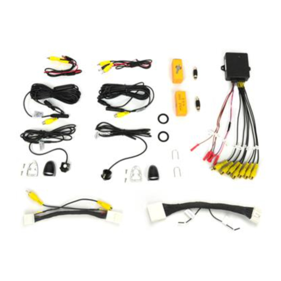
Items Included in the Kit:
2 Adjustable angle cameras
2 Camera pods
2 Chassis harness
2 Foam gaskets
Mounting screws
2 Power/video harness
2 Hole saws
2 Angle adjustment tools
6-way video switcher
16-pin connector harness with RCAs
28-pin connector harness
These instructions
Safety Precautions:
• Work in well ventilated area that is clear of obstructions.
• Secure vehicle with tire chucks in both front and rear of tires.
• Turn vehicle accessories OFF and ensure ignition key is in OFF position.
• Wear safety goggles and snug fitting clothes.
• Use tools only for their intended purpose and which are in good repair.
• Only perform this task if confidence, skill, and physical ability permit.
Toyota 16-pin Dual Camera Blind Spot
Monitoring System (Kit # 9002-2910)
Tools & Supplies Needed:
Wire strippers
Wire cutters
Electrical tape
Zip ties
Plastic panel removal tools
Digital Volt Meter / BCM safe test light
Screwdriver
Socket set
Wrench
Page 1 of 5
GS
Advertisement
Table of Contents

Subscribe to Our Youtube Channel
Related Manuals for BrandMotion 9002-2910


Summary of Contents for BrandMotion 9002-2910
- Page 1 INSTALLATION INSTRUCTIONS Toyota 16-pin Dual Camera Blind Spot Monitoring System (Kit # 9002-2910) Please read thoroughly before starting installation and check that kit contents are complete. Items Included in the Kit: Tools & Supplies Needed: 2 Adjustable angle cameras Wire strippers...
- Page 2 INSTALLATION INSTRUCTIONS 1. Remove the inner door panel to gain access 6. Mount pods by screwing from the inside of the to the wiring and side view mirror mounting mirror. Using a Phillips number 1 tip with a ¼ wrench works the best. bolts.
- Page 3 INSTALLATION INSTRUCTIONS 10. Connect the BLACK wire to ground and the RED input trigger wire is PURPLE, the right input wire to accessory 12-volt power. Repeat for trigger wire is PINK. the other door. 21. Connect the BLUE reverse trigger output wire 11.
- Page 4 INSTALLATION INSTRUCTIONS Connect to REV OUT (step 14) Connect to REV IN (step 13) Page 4 of 5...
- Page 5 INSTALLATION INSTRUCTIONS DIAGRAM #2 (POSITIVE VIDEO) TERMINAL #12 Terminal #8—Positive video TERMINAL #24 (NEGATIVE VIDEO) Terminal #16—Negative video 16 Terminal Connector 24 TERMINAL CONNECTOR (Radio Side) (RADIO SIDE) CONNECT TO THE VIDEO OUT RCA OF THE 6-WAY SWITCHER CUT WIRES 12 AND 24 ADD A FEMALE RCA TO THE RADIO SIDE CONNECTOR ADD A MALE RCA CONNECTOR TO...
Need help?
Do you have a question about the 9002-2910 and is the answer not in the manual?
Questions and answers