
Subscribe to Our Youtube Channel
Related Manuals for Pololu SMC01A


Summary of Contents for Pololu SMC01A
-
Page 1: Table Of Contents
Dual Serial Motor Controller User’s Guide Contents: Safety Warning Parts List Contacting Pololu How to Solder Assembly Instructions Connecting the Motor Controller Using the Motor Controller How the Motor Controller Works Description and Specifications © 2001 http://www.pololu.com/ SMC01A Pololu... -
Page 2: Parts List
Children should use this kit only under adult supervision. By using this product, you agree not to hold Pololu liable for any injury or damage related to the use or to the performance of this product. -
Page 3: Contacting Pololu
Contacting Pololu You can check the Pololu web site at for latest http://www.pololu.com/ information about the motor controller, including color pictures, application examples, and troubleshooting tips. We would be delighted to hear from you about your project and about your experience with our motor controller. -
Page 4: Assembly Instructions
Insert the 8-pin socket from the top side of the PCB in SMC01A the area indicated U1, and solder. On one side of the socket is a notch that should be aligned with the notch on the PCB drawing. - Page 5 Next, add the tantalum capacitor C2. You may need to SMC01A bend the leads to make them straight so that they will fit. The capacitor is polarized, which means it must only go in one way. Make sure the side labeled with a “+”...
-
Page 6: Connecting The Motor Controller
When building circuits that connect to a PC, be especially careful because you could potentially destroy the PC’s serial port. Before attempting to connect your own electronics to a computer, make sure you know what you are doing! © 2001 http://www.pololu.com/ Pololu... - Page 7 DB9 serial SMC01A to 5V port connector (off C2+) 4.7k to serial control input (’2’) Bold circles indicate pads that are connected 2N2222 to 5V, which you can use to ground (’-’) with the circuit shown on the left The above diagram shows a simple circuit for connecting the motor controller to a PC serial port.
-
Page 8: Using The Motor Controller
This motor controller interface protocol is compatible with other Pololu serial devices such as our servo controller, so you can control multiple Pololu serial devices on a single line. - Page 9 You can individually control up to 62 motors at a time with a single serial line using 31 motor controllers: one with the default program and 30 that are specially programmed. © 2001 http://www.pololu.com/ Pololu...
- Page 10 = 127 to 0 serout 14,32,[$80, 0, 0,speed] pause 20 next for speed = 0 to 127 serout 14,32,[$80, 0, 1,speed] pause 20 next for speed = 127 to 0 serout 14,32,[$80, 0, 1,speed] pause 20 next © 2001 http://www.pololu.com/ Pololu...
-
Page 11: How The Motor Controller Works
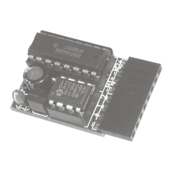
‘+’ and ‘-’ pins. The complete schematic diagram of the motor controller is shown below: LM2931 VOUT PIC12C508A SN754410 1,2EN MCLR 3,4EN VMOT © 2001 http://www.pololu.com/ Pololu... - Page 12 To control additional motors, you can connect multiple motor controllers to the same serial line. The motor controller is compatible with the Pololu Servo Controller, so you can control an almost unlimited number of motors and servos with one serial line. Because of its small size, the motor controller can fit almost any robot design.
Need help?
Do you have a question about the SMC01A and is the answer not in the manual?
Questions and answers