Table of Contents

Related Manuals for Schindler CAL MEDIA MVPHD-24

Summary of Contents for Schindler CAL MEDIA MVPHD-24
- Page 1 Schindler Imaging Inc. MVPHD-24 Video Frame Rate Converter Preliminary Operations Manual Firmware version 0.9.0 Schindler Imaging a trademark of California Media Engineering Inc. MVPHD-24 Operations Manual Version 0.9.0 October 26, 2020...
- Page 2 Cal Media. Cal Media assumes no responsibility or liability for errors or inaccuracies that may appear in this manual. Trademarks Schindler Imaging • is a trademark of California Media Engineering Inc.
- Page 3 Important Regulatory and Safety Notices Before using this product and any associated equipment, refer to the “Important Safety Instructions” listed below so as to avoid personnel injury and to prevent product damage. Products may require specific equipment, and /or installation procedures be carried out to satisfy certain regulatory compliance requirements.
- Page 4 Maintenance/User Serviceable Parts Routine maintenance to this product is not required. This product contains no user serviceable parts other than 5 output factory calibration adjustments. If this product does not appear to be working properly, please contact Technical Support using the contact information on the last page of this manual. The MVPHD-24 is covered by a generous 5-year warranty and will be repaired without charge for materials or labor within this period.
-
Page 5: Table Of Contents
Contents Chapter 1 - Introduction ..........................9 A Word of Thanks ..................................9 Overview ....................................9 Features ....................................10 Quick Start Guide – Basic Setup .............................. 11 Detailed Description ................................. 12 Video Processing .................................. 12 Audio Processing (FUTURE RELEASE) ..........................15 Remote Control .................................. - Page 6 Menu: Output Gain (%): RGB............................26 Menu: Output Gamma: RGB ............................26 Menu: Output Pedestal (%): RGB ..........................26 OUTPUTS: ..................................27 Menu: Output Frame Rate: ............................27 Menu: Output Format: ..............................27 Menu: Primary Output Mode: ............................27 Menu: Composite Standard: ............................27 Menu: Output YPbPr Level: ............................
- Page 7 Menu: Fan Speed ................................39 DashBoard™ Controls ................................40 Control Menus ..................................40 TIMING: ..................................41 Genlock Source: ................................41 Vertical Phase (deg): ..............................42 Horiz Phase (clocks): ..............................42 Subcarrier Phase (deg): ............................... 42 Free Run Freq Adj (ppm): ............................42 Proc Amp: (FUTURE RELEASE) ...........................
- Page 8 Horzontal and Vertical Position Controls ..........................55 Sampling Phase (Sharpness)..............................55 Figure 7-1. Example of VGA “stair-step” signal ......................55 Figure 7-2. Example of Video “linear” signal ......................... 55 Figure 7-3. Example of incorrect sampling phase (distorted) ..................55 Figure 7-4. Example of centered sampling phase (sharp) ....................55 Auto Sample Phase ...................................
-
Page 9: Chapter 1 - Introduction
Schindler Imaging has incorporated the functionality of other equipment with our high quality processing, producing a single unit solution to simplify the task of 24 frame playback. -
Page 10: Features
Features Supports 23.98, 24.00, 25.00, 29.97, and 30.00 Fps frame-rates. Designed specifically for 24 frame video playback Similar look and feel to older model MVP-24 Supports SD, HD, and graphic resolutions up to 1080p for inputs and outputs ... -
Page 11: Quick Start Guide - Basic Setup
Quick Start Guide – Basic Setup Input Connection: Connect the source to the appropriate input connector: Composite video connects to INPUTS - CBVS/R/Pr BNC connector. Y/C video connects to INPUTS - Y/G/Y and C/B/Pb BNC connectors. Component YPbPr video connects to INPUTS - CBVS/R/Pr, Y/G/Y and C/B/Pb BNC connectors. Component RGB video connects to INPUTS - CBVS/R/Pr, Y/G/Y and C/B/Pb BNC connectors. -
Page 12: Detailed Description
Detailed Description Video Processing The MVPHD-24 uses a 3 dimensional COMB filter for the composite input, and a motion compensated processor to de- interlace all interlaced video formats to full progressive video. All processing is performed on the progressive images at 10 bit resolution per channel. - Page 13 HDMI Input The HDMI input supports video formats from SD to HD resolutions and graphic formats up to 1920x1080p. VGA Input The VGA input accepts standard VGA resolutions up to 1920x1080p. Still Image Buffers The MVPHD-24 has four still image buffers which may be selected as input sources. Each image is stored in FLASH memory, and automatically reloaded on power-up.
- Page 14 Primary Output Mode The MVPHD-24 is not capable of producing perfect images on all outputs simultaneously. Therefore the primary output mode is used to select the desired output that is most important. The other outputs may continue to work but the quality may be degraded. Output Frame Rate and Formats All output signals from the MVPHD-24 operate at the chosen frame rate (23.976, 24.000, 25.000, 29.970, or 30.000 Fps).
-
Page 15: Audio Processing (Future Release)
Audio Processing (FUTURE RELEASE) The MVPHD-24 contains synchronization and channel multiplexing for embedded audio signals. SDI Audio Inputs (FUTURE RELEASE) The SDI signal provides for sixteen channels of audio (4 embedded groups of 4 channels). When SDI is selected as the input, these sixteen audio channels are available as audio sources. HDMI Audio Inputs (FUTURE RELEASE) The HDMI signal provides for eight channels of audio (4 stereo pairs). -
Page 16: Chapter 2 - Installation And Setup
Chapter 2 Installation and Setup Chapter 2 - Installation and Setup In This Chapter This chapter contains the following sections: • Static Discharge • Unpacking • Rear Panel Connections • SD/MMC Memory Card Static Discharge Whenever handling the MVPHD-24 and other related equipment, please observe all static discharge precautions as described in the following note: Static discharge can cause serious damage to sensitive semiconductor devices. -
Page 17: Rear Panel Connections
Rear Panel Connections Figure 2-1. Rear Panel Connectors Power Entry Module Using an IEC-C13 power cord, connect to an AC power source. This product is intended to operate from a power source of 100 - 120 VAC (60 Hz), or 200 - 240 VAC (50 Hz). A protective ground connection, by way of the grounding conductor in the power cord, is essential for safe operation. - Page 18 VGA Outputs These DB15-HD female connectors produce standard VGA resolutions up to 1920x1080p. HDMI Output This HDMI Type A connector produces video formats from SD to HD resolutions and graphic formats up to 1920x1080p. SDI Outputs These BNCs connectors produce standard SDI signals at SD (270Mb/s) and HD (1.485Gb/s – 2.97Gb/s) formats up to 1080p-60.
-
Page 19: Sd/Mmc Memory Card
SD/MMC Memory Card The memory card is used for updating the firmware, and for storage of still images. This section provides information for using a memory card on the MVPHD-24. Hot Swappable The memory card is “hot-swappable”, which means it can be installed and removed while the MVPHD-24 is powered and running, without causing interruption. -
Page 20: Chapter 3 - Operation
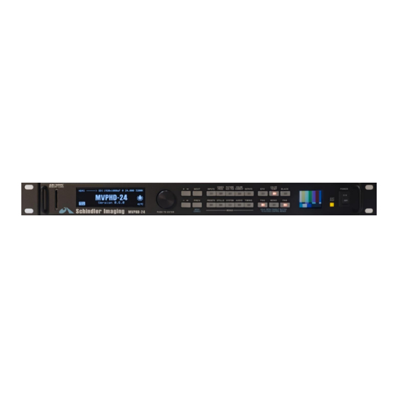
Chapter 3 Operation Chapter 3 - Operation The MVPHD-24 is controlled by the front panel, or remotely by using DashBoard™ Control Software. Front Panel Control Figure 3-1. Front Panel Controls Display The MVPHD-24 utilizes a graphic OLED display to report status information, and to assist the operator while making adjustments. -
Page 21: Controls
Controls The MVPHD-24 is controlled by a menu driven system. Control menus are divided into categories and selected by pressing one of the ten category buttons. When a category is active, the corresponding button will illuminate yellow and a control menu will appear on the front panel display. Pressing NEXT or PREV (previous) will step through all the control menus available for that category. -
Page 22: Menu: Vga Input Vert Position
Menu: VGA Input Vert Position: This menu is used to adjust the vertical position of the VGA input’s capture window. In auto mode (default), the MVPHD-24 automatically adjusts the position. In manual mode, the current position is indicated in BOLD on the second line. *See Chapter 7 for further discussion of the VGA capture window. -
Page 23: Video Proc
VIDEO PROC: This button is used to access menus for the video proc amp. The Proc Amp controls allow adjustments of the selected input signal. Video Level, Setup, Chroma Level, Hue, and Y/C Delay may be used to correct errors in the incoming signal. Note: a “PROC”... -
Page 24: Picture Size/Pos
PICTURE SIZE/POS: This button is used to access menus for the picture size and position controls. Menu: Vert Size: This menu is used to adjust the size of the video outputs’ active picture in the vertical (up-down) direction. This menu displays the size in both percent and number of active lines. -
Page 25: Menu: Zoom Center: Horz Or Vert
Menu: Zoom Center: Horz or Vert This menu is used to position the video input when “Video Zoom” is greater than 100%. The position is displayed in percent. Adjustments are made in the horizontal or vertical direction, indicated on the top line. The direction is selected by pushing the Knob. (Note: This setting has no effect if “Video Zoom”... -
Page 26: Color Correct
COLOR CORRECT: This button is used to access menus for color correction. The Color Correct controls (Gain, Gamma, and Pedestal) may be used to adjust the video image in the RGB color space. All output signals are affected by these controls. Note: a special icon will appear on the right side of the display when any Color Correction control is set to a non-unity value. -
Page 27: Outputs
OUTPUTS: This button is used to access menus for output configuration. Menu: Output Frame Rate: This menu is used to select the base frame rate of all the outputs of the MVPHD-24. The base frame rates 23.976, 24.000, 25.000, 29.970, and 30.000 are supported. Multiples of these frame rates are possible, depending on the selected format. -
Page 28: Menu: Vga Frequency Trim
Menu: VGA Frequency Trim: This menu is only available when VGA is the selected output mode (see Primary Output Mode to select VGA). This menu is used to adjust the VGA outputs’ horizontal frequency. The MVPHD-24 allows the total number of lines per frame to be increased or decreased, thus changing the horizontal frequency while maintaining the correct refresh (frame) rate. -
Page 29: Timing
TIMING: This button is used to access menus for output timing. Menu: Genlock Source: This menu selects the source to be used for locking the output timing of the MVPHD-24. [Genlock BNC] This selection locks the output timing to a reference signal connected to the rear panel’s GENLOCK LOOP BNCs. -
Page 30: Menu: Free Run Freq Adj
Menu: Free Run Freq Adj: This menu is used to vary the MVPHD-24’s master clock frequency while in Free Run mode. Use the Knob or +/- buttons to adjust. Menu: Genlock Status: This menu provides detailed status information on the selected genlock source. The lock status is displayed to the right of “Genlock Status:”... -
Page 31: System
SYSTEM: This button is used to access various MVPHD-24 system menus. Menu: Display Brightness: This menu is used to adjust the brightness of the front panel OLED control display. Use the Knob or +/- buttons to adjust. Menu: Video Reference A.R.C.: This menu is used to select the Aspect Ratio Conversion (A.R.C.) used for the front panel video display and the composite reference outputs, when the selected Output Format is 16x9. -
Page 32: Menu: Motion Filter
Menu: Motion Filter: This menu is used to select the type of motion filtering that is used when frame rate converting. Note: the motion filter setting is automatically reset to “Quadratic” on power-up. [Quadratic] This is the highest quality filter which uses information from three consecutive frames to minimize any video motion artifacts. -
Page 33: Menu: Load Buffer #1 From Sd Card
Menu: Load Buffer #1 from SD Card: This menu is used to load a still image into BUFFER #1 from the SD/MMC memory card. The image currently contained in the buffer is displayed in bold. Use the Knob (rotate) or +/- buttons to select desired still image. ... -
Page 34: Menu: Delete Image From Sd Card
Menu: Delete Image from SD Card: This menu is used to remove an image from the SD/MMC Card. Use the Knob (rotate) to select the image to be deleted. Once selected, press both + and – together to delete the image. PRESETS: This button is used to access menus for Presets. -
Page 35: Active Buttons
Active Buttons There are six active buttons which are located to the right of the ten category buttons. They are used to turn on and off effects, test signals, color temperature, monochrome, go to black, and the chassis fan. When an active button is pressed alone, it activates or de-activates the named function. -
Page 36: Efx (Effects)
(Active Buttons continued) EFX (Effects): Limited effects can be applied to the video signal using the EFX button, such as: Freeze, Fade to Black, Video Noise, and Synchronized Snow. The EFX button (when pressed alone) toggles the selected effect ON or OFF. Pressing EFX while holding down the MENU ENABLE button will open the EFX control menus. -
Page 37: Tsg (Test Signal Generator)
(Active Buttons continued) TSG (Test Signal Generator): This button (when pressed alone) will enable or disable the video test signal generator. Pressing TSG while holding down the MENU ENABLE button will open the TSG control menus. Pressing NEXT or PREV (previous) will step through the TSG control menus. Menu: Video Test Signal This menu is used to select which video test signal is displayed. -
Page 38: Color Temp (Color Temperature)
(Active Buttons continued) COLOR TEMP (Color Temperature): This button (when pressed alone) will enable or disable color temperature settings. When enabled, the status line of the display will indicate the color temp (if preset used) or USER. When disabled, the status line of the display will indicate 6500 , which is the default color temperature for a video monitor. -
Page 39: Mono (Monochrome)
(Active Buttons continued) MONO (Monochrome): This button (when pressed alone) will enable or disable monochrome mode. When enabled, all color information is removed from the video outputs leaving a black and white picture. There are no menus available for this function. BLACK (Go to Black): This button (when pressed alone) will enable or disable Black mode. -
Page 40: Dashboard™ Controls
DashBoard™ Controls The MVPHD-24 can be controlled using the DashBoard™ Control System. Add section about Dashboard software and how to download. Note: The MVPHD-24 must be connected to the network before turning the power on, to enable a connection with Dashboard. The MVPHD-24 usually takes approximately 90 seconds after power is turned on, before communications with Dashboard begin. -
Page 41: Timing
TIMING: This menu tab is used to access output timing controls. Genlock Source: This control selects the source to be used for locking the output timing of the MVPHD-24. Use the Genlock Source drop-down control to choose which signal will be used as the genlock reference (The Product menu tab indicates the genlock status for the selected reference). -
Page 42: Vertical Phase (Deg)
The following controls adjust the timing of the video frame synchronizer. Because of internal processing delays (approx. 3+ lines), a phase setting of zero clocks / zero lines will guarantee one frame of delay in the synchronizer. Vertical Phase (deg): This slider control is used to vary the vertical phase of all the output signals from the MVPHD-24 (including the sync reference outputs). -
Page 43: Proc Amp: (Future Release)
Proc Amp: (FUTURE RELEASE) The Proc Amps menu tab contains controls for adjusting the selected video input. Note: these controls apply to the video signal before images are captured for stills or freezing. The Proc Amp Controls button is used to enable or disable all four Proc Amp controls. When set to ON, the Proc Amp controls are active. -
Page 44: Product Menu (Status)
Product Menu (Status) The Product menu tab displays various information about the MVPHD-24. Hours of Operation indicates how long this particular MVPHD-24 card has been powered. This is only an approximate time. The value is updated every 3.75 minutes. Note: Brand new units will have a typical value between 72 and 80 hours. This is due to standard 72 hour “burn-in”... -
Page 45: Chapter 4 - Overview Of 24 Fps Video Playback
Chapter 4 Overview of 24 Fps Video Playback Chapter 4 – Overview of 24 Fps Video Playback Introduction There are three factors that affect the camera’s ability to film a television monitor; the frame rates of the camera and monitor, the phase of the camera’s shutter and the monitor, and the shutter angle of the camera. What follows is a simplified description of these factors. -
Page 46: Shutter Phase
Shutter Phase Once the video’s frame rate is made equal to the camera’s frame rate, then the phases of the camera’s shutter and the monitor become important. It will be assumed that the camera’s shutter is open 50% of the time and closed the other 50%. - Page 47 SCA NNED VIDEO RESULTING SHUTTER IMA GES PICTURE TIME BOTTOM OPEN BOTTOM BOTTOM CLOSED Figure 4-3. Example of shutter angle > 180 degrees. TIME BOTTOM OPEN BOTTOM BOTTOM CLOSED Figure 4-4. Example of shutter angle < 180 degrees. In Figure 4-3, the shutter angle is greater than 180 degrees. As can be seen from this example, a small portion of the image is seen by the film twice, double exposing it and creating a light horizontal band in the picture.
- Page 48 TIME OPEN BOTTOM BOTTOM CLOSED BOTTOM BLANKING INTERVAL Figure 4-5. Example of shutter angle > 180 degrees, with 0 degrees of shutter phase. Figure 4-5 demonstrates the condition when the shutter and the image are in alignment. Even though the shutter angle is greater than 180 degrees, the area of the image that would be double exposed is now blanked.
-
Page 49: Chapter 5 - Tips And Suggestions
Chapter 5 Tips and Suggestions Chapter 5 – Tips and Suggestions Introduction The MVPHD-24 comes equipped with many features to help with the varying demands of video playback. This chapter offers suggestions on various configurations and the use of the MVPHD-24’s special features to simplify the task of video playback. -
Page 50: Color Temperature
Color Temperature The color temperature of a standard television monitor is 6500 degrees. Therefore it must be adjusted to match the ambient lighting in the scene being filmed. It is possible to individually adjust each monitor’s screen controls to set them to the proper temperature;... -
Page 51: Synchronization
Synchronization For proper setup, the Camera(s) and the television monitor(s) must be synchronized. This is typical done by supplying a master reference to all the cameras and video equipment used. MVPHD-24 as Master Reference MVPHD-24 The MVPHD-24 has an internal sync generator which may be used for the as Master master reference. -
Page 52: Phasing Using F1-Blu/F2-Yel Test Signal
Phasing Using F1-BLU/F2-YEL Test Signal Phasing Using The MVPHD-24 generates a special test signal for the purpose of phasing the camera with the monitor (“F1-BLU/F2-YEL”). It is a field alternating signal F1-BLU/F2-YEL Test Signal that appears to the eye as a gray flashing image. The signal is actually blue in field one, and yellow in field two. -
Page 53: Wide Camera Shutter Angles (>> 180 Degrees)
Wide Camera Shutter Angles (>> 180 degrees) In order to film standard 24 Fps video, the camera shutter angle needs to be approximately 180 degrees. Often times however, larger shutter angles are desired or required by the director. Using the MVPHD-24, it is possible to increase the shutter angle and still avoid any artifacts in the picture. -
Page 54: Chapter 6 - Vga Input Processing
Chapter 6 VGA Input Processing Chapter 6 – VGA Input Processing Introduction The MVPHD-24 is a digital processing unit. In order to process analog signals, the MVPHD-24 must first convert the signal from analog to digital. This is achieved by a method called “digital sampling”. The analog signal is “sampled”... -
Page 55: Horzontal And Vertical Position Controls
Horzontal and Vertical Position Controls Two menus are provided to control the position of the sampled picture: “VGA Input Vert Position” and “VGA Input Horz Position” In “Auto” mode, these menus indicate the position values determined by the “Auto” positioning algorithm. These menus can also be used to override the “Auto”... -
Page 56: Sample Phase Control
Sample Phase Control A menu is provided to control the sampling phase: “VGA Input Sample Phase” In “Auto” mode, this menu indicates the phase value determined by the “Auto” phase algorithm. This menu can also be used to override the “Auto” mode and manually adjust the sample phase. “Manual”... -
Page 57: Chapter 7 - Using Still Image Buffers
Chapter 7 Using Still Image Buffers Chapter 7 – Using Still Image Buffers Introduction The MVPHD-24 has four FLASH Still Image buffers available for use as input sources. The contents of these Still Image buffers are stored in non-volatile FLASH memory and retained even when power is removed from the unit. Still Images The Still Image buffers can hold full-frame full-color images up to 1080p resolution. -
Page 58: Loading Still Images From Sd Card
Loading Still Images from SD Card The Still Image Buffers can be loaded from the SD/MMC Card. Still image files must be located on the SD/MMC Card in a folder named “STILLS”. The MVPHD-24 uses a proprietary format for loading or storing images of various resolutions at 20bit 4:2:2 quality. -
Page 59: Menu: Save Output Image To Sd Card
Still images may be captured and saved to a SD/MMC Card for later use, or to transfer to other MVPHD-24s. To access Still Image Buffer menus, press the STILLS button. This will open the Still Image Buffer control menus. Pressing NEXT or PREV (previous) will step through the control menus. Menu: Save Output Image to SD Card: This menu is used to capture an image from the MVPHD-24’s output, and save it to the SD/MMC Card. -
Page 60: Chapter 8 - Adding Custom Test Signals
Chapter 8 Adding Custom Test Signals Chapter 8 – Adding Custom Test Signals Introduction The MVPHD-24 has eight FLASH Image buffers available for use as customer created test signals. The contents of these TSG buffers are stored in non-volatile FLASH memory and retained even when power is removed from the unit. To load a custom TSG image, a Custom Key is required. -
Page 61: Menu: Capture Output To Customtsg
Menu: Capture Output to CustomTSG ?: This menu is used to capture an image from the MVPHD-24’s output, and store it into the selected Custom TSG buffer. A suggested name for the test signal is provided, which can be edited. ... -
Page 62: Menu: Load Customtsg5 From Sd Card
Menu: Load CustomTSG5 from SD Card: This menu is used to load a still image into the CustomTSG5 buffer from the SD/MMC memory card (see above for more details). Menu: Load CustomTSG6 from SD Card: This menu is used to load a still image into the CustomTSG6 buffer from the SD/MMC memory card (see above for more details). - Page 63 Updating the Sizing Charts uses the Batch Load process. To begin the update process, first turn the MVPHD’s power switch off. A SD/MMC Card must be installed on the front panel which contains both the Custom Key and the “CUSTOM” folder (both located in the root directory). Press the TSG button while turning the power switch on, and continue pressing the TSG button until the message “Loading *.TSn…”...
-
Page 64: Chapter 9 - Updating The Firmware
Chapter 9 Updating the Firmware Chapter 9 – Updating the Firmware The MVPHD-24 can be quickly and easily updated using a MMC or SD memory card, or remotely through Dashboard. Obtaining New Firmware The current version of firmware can be obtained from California Media Engineering (www.calmedia.com). Preparing Firmware Files The firmware will be provided as a .zip file. -
Page 65: Installing Firmware Using A Sd Or Mmc Memory Card
Installing Firmware using a SD or MMC Memory Card Install the memory card containing the update folder on the front panel of the MVPHD-24 (see section Installation and Setup for details). Press the "SYSTEM" button to bring up system menus. Using the NEXT or PREV buttons, locate the "Update Firmware"... -
Page 66: Installing Firmware Using Dashboard™ (Future Release)
Installing Firmware using Dashboard™ (FUTURE RELEASE) Note: This process typically takes about 2 minutes. Launch the Dashboard™ application and open the MVPHD-24 device listed in the Basic Tree View. Click on the Upload button at the bottom of the Dashboard™ control screen. The Upload Software Wizard will open. -
Page 67: Troubleshooting Firmware Installation
Troubleshooting Firmware Installation Troubleshooting Memory Card Firmware Installation If nothing happens when the + and – buttons are pressed together, check the following: 1. The MMC or SD memory card is not fully installed. 2. Possible bad memory card. Check if the memory card is correctly identified on the front panel display. Try a different memory card. -
Page 68: Appendix A - Specifications
Appendix A Specifications Appendix A - Specifications ANALOG INPUTS: Composite 1.0 Vpp (including sync) CBVS / R / Pr BNC, 75 (Y) 1.0 Vpp (including sync) Y / G / Y BNC, 75 (C) 700 mVpp C / B / Pb BNC, 75... - Page 69 ANALOG OUTPUTS: Composite 1.0 Vpp (including sync) CBVS / R / Pr BNC, 75 (Y) 1.0 Vpp (including sync) Y / G / Y BNC, 75 (C) 700 mVpp C / B / Pb BNC, 75 (Red) 700 mVpp CBVS / R / Pr BNC, 75...
- Page 70 VIDEO PERFORMANCE Composite, Y/C Inputs: Bandwidth 5.0 MHz Signal Filter Digital Adaptive 3D-COMB filter Signal to Noise Ratio >58 dB (weighted, 10KHz to 5 MHz) Differential Phase <2 deg Differential Gain <2% K-Factor (2T Pulse) <2% 4 x over-sampling 10 bit ADC 4:2:2, 54 MHz Component YRB/RGB Inputs: Bandwidth 5.5 MHz...
-
Page 71: Appendix B - Pinouts
Appendix B Pinouts Appendix B - Pinouts GPIO Pin out GPIO1 GPIO2 GPIO3 SPARE GPIO4 +5v 500mA GPIO5 SPARE GPIO6 GPIO7 GPIO8 MVPHD-24 Operations Manual Version 0.8.5 page 71 of 74 October 26, 2020... -
Page 72: Year Limited Warranty
5 YEAR LIMITED WARRANTY California Media Engineering Inc. warrants that this product (MVPHD-24) is free from defects in material or workmanship for a period of five (5) years from the date of original purchase. In the event this product becomes defective through normal usage, California Media Engineering Inc. -
Page 73: Repair Policy
Repair Policy Should any problem arise with your MVPHD-24, please contact Cal Media’s Technical Support Department at support@calmedia.com or use the contact information on the back cover of this manual. If required, a Return Material Authorization number (RMA) will be issued to you, as well as specific shipping instructions. - Page 74 California Media Engineering Inc. Voice: (805) 931-0857 info@calmedia.com support@calmedia.com...
Need help?
Do you have a question about the CAL MEDIA MVPHD-24 and is the answer not in the manual?
Questions and answers