
Related Manuals for Arbor Technology EmETXe-a58M0


Summary of Contents for Arbor Technology EmETXe-a58M0
- Page 1 EmETXe-a58M0 COM Express Compact ® Type 6 CPU Module User’s Manual Version 1.0 2016.02...
- Page 2 Revision History Version Date Description FEB, 2016 Initial release...
-
Page 3: Table Of Contents
Contents Preface Copyright Notice ..............iii Declaration of Conformity ..........iii CE ..................iii FCC Class A .................iii RoHS ..................iv SVHC / REACH ..............iv Warning ................v Replacing the Lithium Battery ...........v Technical Support ..............v Warranty ................vi Chapter 1 - Introduction 1.1 The Product ..............2 1.2 About This Manual............2 1.3 Specifications ..............3 1.4 Inside the Package ............4... - Page 4 Content Chapter 4 - BIOS 4.1 Main ................20 4.2 Advanced..............22 4.2.1 ACPI Settings ............23 4.2.2 CPU Configuration ...........24 4.2.3 IDE Configuration .............25 4.2.4 SDIO Configuration ..........26 4.2.5 USB Configuration ...........27 4.2.6 Super IO Configuration ..........29 4.2.7 H/W Monitor ..............30 4.2.8 Network Stack Configuration ........31 4.3 Chipset ...............32 4.3.1 South Bridge .............33 4.3.2 North Bridge ..............38...
-
Page 5: Preface
Preface Copyright Notice All Rights Reserved. The information in this document is subject to change without prior notice in order to improve the reliability, design and function. It does not represent a commitment on the part of the manufacturer. Under no circumstances will the manufacturer be liable for any direct, indirect, special, incidental, or consequential damages arising from the use or inability to use the product or documentation, even if advised of the possibility of such damages. -
Page 6: Rohs
RoHS ARBOR Technology Corp. certifies that all components in its products are in compliance and conform to the European Union’s Restriction of Use of Haz- ardous Substances in Electrical and Electronic Equipment (RoHS) Directive 2002/95/EC. -
Page 7: Warning
Preface Warning Single Board Computers and their components contain very delicate Integrated Circuits (IC). To protect the Single Board Computer and its components against damage from static electricity, you should always follow the following precautions when handling it : 1. Disconnect your Single Board Computer from the power source when you want to work on the inside. -
Page 8: Warranty
Preface Warranty This product is warranted to be in good working order for a period of two years from the date of purchase. Should this product fail to be in good working order at any time during this period, we will, at our option, replace or repair it at no additional charge except as set forth in the following terms. -
Page 9: Chapter 1 Introduction
Introduction Chapter 1 Introduction - 1 -... -
Page 10: The Product
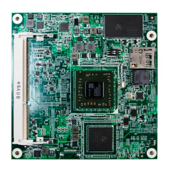
Introduction 1.1 The Product The EmETXe-a58M0 is a space-conscious CPU board of 95 mm x 95 mm to take up only small footprint in your system. By the architecture of Type 6, the board has two high-performance connectors to promise stable data passing rate. -
Page 11: Specifications
Introduction 1.3 Specifications System AMD APU G-series SoC GX-412HC processor 1 x DDR3L SO-DIMM socket, up to 8GB 1666MT/s Memory SDRAM BIOS UEFI BIOS ® Watchdog Timer 1~255 levels reset 7 x USB 2.0 ports USB Port 2 x USB SS ports (Super Speed) Expansion Bus 7x PCIe x 1 Lanes, SDIO 2 x Serial ATA ports with 600MB/s HDD transfer rate... -
Page 12: Inside The Package
Introduction 1.4 Inside the Package Before you begin installing your single board, please make sure that the following materials have been shipped: 1 x EmETXe-a58M0-412HC COM Express CPU Module 1 x Driver CD 1 x Quick Installation Guide If any of the above items is damaged or missing, contact your vendor immediately. -
Page 13: The Installation Paths Of Cd Driver
CD that comes with your purchase. For different OS, the driver installation may vary slightly, but generally they are similar. Find the drivers on CD by the following paths: Windows 8.1 Driver Path \EmETXe-a58M0\FT3B Chipset\Win8.1 64 bit\14.502.1030- Chipset 150428a-183767C-AES Win 32: \EmETXe-a58M0\Audio\32bit Audio Win 64: \EmETXe-a58M0\Audio\64bit... - Page 14 Introduction Windows 7 Driver Path Win 32: EmETXe-a58M0\FT3B Chipset\ Win7\32bit\14.502.1030-150428a-183767C-AES Chipset Win 64: EmETXe-a58M0\FT3B Chipset\Win7\64 bit\14.502.1030-150428a-183767C-AES Win 32: \EmETXe-a58M0\Audio\32bit Audio Win 64: \EmETXe-a58M0\Audio\64bit \EmETXe-a58M0\LAN\RTL81111E for module\Install_ Win7_7061_07272012 USB3.0 \EmETXe-a58M0\USB 3.0\win7 - 6 -...
-
Page 15: Chapter 2 - Board Overview
Board Overview Chapter 2 Board Overview - 7 -... -
Page 16: What Is "Com Express
Module Type 1 and 10 support single connector with two rows (220 pins). Module Type 2, 3, 4, 5 and 6 support two connectors with four rows (440 pins). EmETXe-a58M0 is a Type-6 module. Difference between Standard Type 6 and EmETXe-a58M0 is listed as below: Module Type... -
Page 17: Board Dimensions
Board Overview 2.2 Board Dimensions The following illustration shows the dimension of EmETXe-a58M0, with the mea- surements in width, depth, and height called out. 41,02 Unit:mm - 9 -... -
Page 18: Block Diagram
Board Overview 2.3 Block Diagram DIMM1 DDR3L-1666T/s DDR3L SO-DIMM socket DDI0 DDI1 2 x USB SS ports 1 x PCIex1 Gen2 Pericom 1 x PCIex4 Gen2 PI7C9X2G608GP 3 x PCIex1 Gen2 3 x PCIex1 Gen2 AMD APU HD Audio Link G-series Analog RGB Steppe... -
Page 19: Connector Pin Definition
Board Overview 2.4 Connector Pin Definition Being a most commonly-used Type 6, the EmETXe-a58M0 features two board- to-board connectors on bottom side. Top Side SO-DIMM socket SDIO socket SATA NANDrive (Optional) Bottom Side SO-DIMM socket - 11 -... - Page 20 Board Overview (bottom side) COM Express AB Connector B56 PCIE_RX4- PCIE_TX4- A56 B1 GND GND A1 B2 GBE0_ACT# GBE0_MDI3- A2 B57 GPO2 GND A57 B58 PCIE_RX3+ PCIE_TX3+ A58 B3 LPC_FRAME# GBE0_MDI3+ A3 B4 LPC_AD0 GBE0_LINK100# A4 B59 PCIE_RX3- PCIE_TX3- A59 B60 GND GND A60 B5 LPC_AD1...
- Page 21 Board Overview COM Express CD Connector (bottom side) D1 GND GND C1 D56 PEG_TX1-(N/C) PEG_RX1-(N/C) C56 D2 GND GND C2 D57 TYPE2#(N/C) TYPE1#(N/C) C57 D3 USB_SSTX0- USB_SSRX0- C3 D58 PEG_TX2+(N/C) PEG_RX2+(N/C) C58 D4 USB_SSTX0+ USB_SSRX0+ C4 D59 PEG_TX2-(N/C) PEG_RX2-(N/C) C59 D5 GND GND C5 D60 GND...
-
Page 22: Jumper Setting
Board Overview 2.5 Jumper Setting SW1: SATA port selection Pin Mode Set to SATA port (default) Set to NANDrive - 14 -... -
Page 23: Chapter 3 - Installation & Maintenance
Installation & Maintenance Chapter 3 Installation & Maintenance - 15 -... -
Page 24: Installing The Cpu Module On Carrier Board
1. Find the COM Express connectors on carrier board PBE-1702, which is available in Section 1.5.1 Optional Accessories on page 2. Embed EmETXe-a58M0 into PBE-1702 via COM Express connectors as below; that is, COM Express AB to AB and CD to CD. - 16 -... -
Page 25: Installing The Heatsink
Installation & Maintenance 3.2 Installing the Heatsink 1. Locate EmETXe-a58M0 mounted on PBE-1702. 2. Prepare the heatspred included in optional accessories. (See Section 1.5.1 Optional Accessories on page 4) Put heatspred on the CPU module and lock it. Make sure thermal grease in contact with CPU and chipset on CPU module. - Page 26 This page is intentionally left blank. - 18 -...
-
Page 27: Chapter 4 - Bios
BIOS Chapter 4 BIOS - 19 -... -
Page 28: Main
The Main Setup screen lists the following information: Aptio Setup Utility - Copyright (C) 2016 American Megatrends, Inc. Main Advanced Chipset Boot Security Save & Exit BIOS Information Choose the system default BIOS Name EmETXe-a58M0 language BIOS Version 1.07 Build Date and Time 01/13/2016 13:40:09 Memory Infomration... - Page 29 BIOS Delivers the level by which the BIOS Setup utility is Access Level being accessed at the moment. Key Commands BIOS Setup Utility is mainly a key-based navigation interface. Please refer to the following key command instructions for navigation process. Keystroke Function Move to highlight a particular configuration screen from...
-
Page 30: Advanced
BIOS 4.2 Advanced The “Advanced” setting page provides you the options to configure the details of your hardware, such as ACPI, CPU, SATA, AMT, USB and Super IO. Aptio Setup Utility - Copyright (C) 2016 American Megatrends, Inc. Main Advanced Chipset Boot Security Save &... -
Page 31: Acpi Settings
BIOS 4.2.1 ACPI Settings Aptio Setup Utility - Copyright (C) 2012 American Megatrends, Inc. Aptio Setup Utility - Copyright (C) 2016 American Megatrends, Inc. Advanced ACPI Settings Select ACPI sleep state the system will ACPI Sleep State [S3 only(Suspend to ...] enter when the SUSPEND Enable Hibernation [Enabled]... -
Page 32: Cpu Configuration
BIOS 4.2.2 CPU Configuration Access this submenu to configure the CPU features. Aptio Setup Utility - Copyright (C) 2016 American Megatrends, Inc. Advanced CPU Configuration View Memory Information related to Node 0 Node 0 Information →←: Select Screen ↓↑: Select Item Enter: Select +/-: Change Opt. -
Page 33: Ide Configuration
BIOS 4.2.3 IDE Configuration Access this submenu to view the presence of SATA device(s). Aptio Setup Utility - Copyright (C) 2016 American Megatrends, Inc. Advanced IDE Configuration SATA Port0 Not Present SATA Port1 8GB NANDrive (8.0GB) →←: Select Screen ↓↑: Select Item Enter: Select +/-: Change Opt. -
Page 34: Sdio Configuration
BIOS 4.2.4 SDIO Configuration Aptio Setup Utility - Copyright (C) 2012 American Megatrends, Inc. Aptio Setup Utility - Copyright (C) 2016 American Megatrends, Inc. Advanced ACPI Settings Select ACPI sleep state the system will ACPI Sleep State [S3 only(Suspend to ...] enter when the SUSPEND Enable Hibernation [Enabled]... -
Page 35: Usb Configuration
BIOS 4.2.5 USB Configuration Select this submenu to view the status of the USB ports and configure USB features. Aptio Setup Utility - Copyright (C) 2016 American Megatrends, Inc. Main Advanced Chipset Boot Security Save & Exit USB Configuration Enables Legacy USB support. AUTO option disables legacy USB Devices: support if no USB devices are... - Page 36 BIOS Enables/disables a workaround for the operat- EHCI Hand-off ing systems that have no EHCI hand-off support Disabled is the default. USB Mass Enables/disables the support for USB mass storage driver. Storage Driver Enabled is the default. Support - 28 -...
-
Page 37: Super Io Configuration
BIOS 4.2.6 Super IO Configuration Aptio Setup Utility - Copyright (C) 2012 American Megatrends, Inc. Aptio Setup Utility - Copyright (C) 2016 American Megatrends, Inc. Advanced Super IO Configuration Specify what state to go to when power is re-applied after a Super IO Chip F71869E power failure... -
Page 38: H/W Monitor
BIOS 4.2.7 H/W Monitor Aptio Setup Utility - Copyright (C) 2012 American Megatrends, Inc. Aptio Setup Utility - Copyright (C) 2016 American Megatrends, Inc. Advanced Pc Health Status CPU Temperature : +36˚C System Temperature : +36˚C BACKFAN : N/A FrontFAN : N/A : +5.087 V +1.05V... -
Page 39: Network Stack Configuration
BIOS 4.2.8 Network Stack Configuration Aptio Setup Utility - Copyright (C) 2016 American Megatrends, Inc. Advanced Network stack Enable/Disable UEFI [Enabled] IPv4 PXE Support [Enabled] network stack IPv6 PXE Support [Enabled] PXE boot wait time Media detect time →←: Select Screen ↓↑: Select Item Enter: Select +/-: Change Opt. -
Page 40: Chipset
BIOS 4.3 Chipset Aptio Setup Utility - Copyright (C) 2012 American Megatrends, Inc. Main Advanced Boot Security Save & Exit Chipset South Bridge ► South Bridge Parameters ► North Bridge →←: Select Screen ↓↑: Select Item Enter: Select +/-: Change Opt. F1: General Help F2: Previous Values F9: Optimized Defaults... -
Page 41: South Bridge
BIOS 4.3.1 South Bridge Aptio Setup Utility - Copyright (C) 2016 American Megatrends, Inc. Chipset AMD Reference code Version: Mullins PI 1.0.0.6 SB SATA Confuguration SB USB Configuration SB SD Configuration SB HD Azalia Configuration →←: Select Screen ↓↑: Select Item Enter: Select +/-: Change Opt. - Page 42 BIOS 4.3.1.1 SB SATA Configuration Aptio Setup Utility - Copyright (C) 2016 American Megatrends, Inc. Chipset OnChip SATA Channel [Enabled] Enable or Disable Serial ATA OnChip SATA Type [ACHI] Select Screen Select Item Enter Select Change Opt. General Help Previous Values Optimized Defaults Save &...
- Page 43 BIOS 4.3.1.2 SB USB Configuration Aptio Setup Utility - Copyright (C) 2016 American Megatrends, Inc. Chipset XHCI Controller 0 [Enabled] XHCI Enable Help XHCI0 Port 0 [Enabled] XHCI0 Port 1 [Enabled] EHCI HC(Bus 0 Dev 18 Fn 0) [Enabled] USB Internal Port 0 [Enabled] HUB PORT 0 [Enabled]...
- Page 44 BIOS 4.3.1.3 SB SD Configuration Aptio Setup Utility - Copyright (C) 2016 American Megatrends, Inc. Chipset SD Mode [ADMA] SD Mode Configuration. SD Trace Length [Less 6] SD Host Controller Version [SD 2.0] →←: Select Screen ↓↑: Select Item Enter: Select +/-: Change Opt.
- Page 45 BIOS 4.3.1.4 SB HD Azalia Configuration Aptio Setup Utility - Copyright (C) 2016 American Megatrends, Inc. Chipset HD Audio Azalia Device [Enabled] Azalia HD Audio controller Select Screen Select Item Enter Select Change Opt. General Help Previous Values Optimized Defaults Save &...
-
Page 46: North Bridge
BIOS 4.3.2 North Bridge Aptio Setup Utility - Copyright (C) 2016 American Megatrends, Inc. Chipset Memory Information Memory Clock 667 Mhz Total Memory 2032 MB (DDR3) Socket 0 Information →←: Select Screen ↓↑: Select Item Enter: Select +/-: Change Opt. F1: General Help F2: Previous Values F9: Optimized Defaults... - Page 47 BIOS Aptio Setup Utility - Copyright (C) 2016 American Megatrends, Inc. Chipset Starting Address: 0 Ending Address: 1fffff Dimm0: size = 2048MB, speed=800MHz →←: Select Screen ↓↑: Select Item Enter: Select +/-: Change Opt. F1: General Help F2: Previous Values F9: Optimized Defaults F10: Save and Exit ESC: Exit...
-
Page 48: Boot
BIOS 4.4 Boot Aptio Setup Utility - Copyright (C) 2016 American Megatrends, Inc. Main Advanced Chipset Security Save & Exit Boot Number of seconds to Boot Configuration wait for setup Setup Prompt Timeout activation key. Bootup NumLock State [On] 65535(0xFFFF) means indefinite waiting. -
Page 49: Csm16 Parameters
BIOS 4.4.1 CSM16 Parameters Setting Description Select setting for GateA20 GateA20 Active Options: UPON REQUEST (default) and Always ► Set display mode for Option ROM. Option ROM Messages Options: Force BIOS (default) and Keep ► Current. 4.4.2 CSM Parameters Setting Description Enables/disables launching CSM (capability support module), which provides UEFI with the additional func-... - Page 50 BIOS Configures whether to launch the UEFI or legacy Launch Video OpROM of video. OpROM policy Options: Do not launch, UEFI only and Legacy ► only (default). Configures which OpROM to run for the PCI devices Other PCI device other than network, mass storage, or video. ROM priority Options: UEFI OpROM and Legacy OpROM (de- ►...
-
Page 51: Security
BIOS 4.5 Security The Security menu sets up the administrator password. Aptio Setup Utility - Copyright (C) 2015 American Megatrends, Inc. Main Advanced Chipset Security Save & Exit Boot Set Administrator Password Description Password Minimum length Maximum length Administrator Password →←: Select Screen ↓↑: Select Item Enter: Select... -
Page 52: Save & Exit
BIOS 4.6 Save & Exit Aptio Setup Utility - Copyright (C) 2015 American Megatrends, Inc. Main Advanced Chipset Security Boot Save & Exit Exit system setup Save Changes and Exit after saving the Discard Changes and Exit changes. Save Changes and Reset Discard Changes and Reset Restore Defaults Lauch EFI Shell from filesystem device... - Page 53 BIOS Discard Changes done so far to any of the setup Discard Changes options. Restore/Load Default values for all the setup options. Restore Defaults Enter the item and then a dialog box pops up: ► Load Optimized Defaults? (Yes/ No) Save as USER Defaults Save the changes done so far as User Defaults.
- Page 54 This page is intentionally left blank. - 46 -...
-
Page 55: Appendix
Appendix Appendix - 47 -... -
Page 56: Appendix A: I/O Port Address Map
Appendix Appendix A: I/O Port Address Map Each peripheral device in the system is assigned a set of I/O port addresses which also becomes the identity of the device. The following table lists the I/O port addresses used. Address Device Description 0x000003F8-0x000003FF Communications Port (COM1) 0x000002F8-0x000002FF... - Page 57 Appendix 0x000000A2-0x000000BF Motherboard resources 0x000000A2-0x000000BF Motherboard resources 0x000000E0-0x000000EF Motherboard resources 0x000000E0-0x000000EF Motherboard resources 0x000004D0-0x000004D1 Motherboard resources 0x000004D0-0x000004D1 Motherboard resources 0x00000290-0x0000029F Motherboard resources 0x00000063-0x00000063 Motherboard resources 0x00000065-0x00000065 Motherboard resources 0x00000067-0x0000006F Motherboard resources 0x000000B1-0x000000B1 Motherboard resources 0x0000040B-0x0000040B Motherboard resources 0x000004D6-0x000004D6 Motherboard resources 0x00000C00-0x00000C01 Motherboard resources 0x00000C14-0x00000C14...
- Page 58 Appendix 0x000003B0-0x000003BB PCI bus 0x000003E0-0x00000CF7 PCI bus 0x00000D00-0x0000FFFF PCI bus 0x0000E000-0x0000EFFF PCI Express standard Root Port 0x00000378-0x0000037F Printer Port (LPT1) 0x00000020-0x00000021 Programmable interrupt controller 0x000000A0-0x000000A1 Programmable interrupt controller 0x0000F140-0x0000F147 Standard AHCI 1.0 Serial ATA Controller 0x0000F130-0x0000F133 Standard AHCI 1.0 Serial ATA Controller 0x0000F120-0x0000F127 Standard AHCI 1.0 Serial ATA Controller 0x0000F110-0x0000F113...
-
Page 59: Appendix B: Bios Memory Mapping
Appendix Appendix B: BIOS Memory Mapping Address Device Description 0x000003F8-0x000003FF Communications Port (COM1) 0x000002F8-0x000002FF Communications Port (COM2) 0x00000000-0x0000000F Direct memory access controller 0x00000081-0x00000083 Direct memory access controller 0x00000087-0x00000087 Direct memory access controller 0x00000089-0x0000008B Direct memory access controller 0x0000008F-0x0000008F Direct memory access controller 0x000000C0-0x000000DF Direct memory access controller 0x0000E000-0x0000EFFF... - Page 60 Appendix 0x000000E0-0x000000EF Motherboard resources 0x000000E0-0x000000EF Motherboard resources 0x000004D0-0x000004D1 Motherboard resources 0x000004D0-0x000004D1 Motherboard resources 0x00000290-0x0000029F Motherboard resources 0x00000063-0x00000063 Motherboard resources 0x00000065-0x00000065 Motherboard resources 0x00000067-0x0000006F Motherboard resources 0x000000B1-0x000000B1 Motherboard resources 0x0000040B-0x0000040B Motherboard resources 0x000004D6-0x000004D6 Motherboard resources 0x00000C00-0x00000C01 Motherboard resources 0x00000C14-0x00000C14 Motherboard resources 0x00000C50-0x00000C51 Motherboard resources 0x00000C52-0x00000C52...
- Page 61 Appendix 0x00000D00-0x0000FFFF PCI bus 0x0000E000-0x0000EFFF PCI Express standard Root Port 0x00000378-0x0000037F Printer Port (LPT1) 0x00000020-0x00000021 Programmable interrupt controller 0x000000A0-0x000000A1 Programmable interrupt controller 0x0000F140-0x0000F147 Standard AHCI 1.0 Serial ATA Controller 0x0000F130-0x0000F133 Standard AHCI 1.0 Serial ATA Controller 0x0000F120-0x0000F127 Standard AHCI 1.0 Serial ATA Controller 0x0000F110-0x0000F113 Standard AHCI 1.0 Serial ATA Controller 0x0000F100-0x0000F10F...
-
Page 62: Appendix C: Interrupt Request Lines (Irq)
Appendix Appendix C: Interrupt Request Lines (IRQ) Peripheral devices use interrupt request lines to notify CPU for the service required. The following table shows the IRQ used by the devices on board. Level Function IRQ0 System timer IRQ0 High precision event timer IRQ1 Standard PS/2 Keyboard IRQ3... -
Page 63: Appendix D: Watchdog Timer (Wdt) Setting
Appendix Appendix D: Watchdog Timer (WDT) Setting WDT is widely used for industry application to monitor the activity of CPU. Ap- plication software depends on its requirement to trigger WDT with adequate timer setting. Before WDT time out, the functional normal system will reload the WDT. - Page 64 Appendix delay(DELAY_TIME); /* Watchdog Timer Control Register */ SMB_Byte_WRITE(SMB_PORT_AD,SMB_DEVICE_ADD,0x36,0x72); int WDT_Count(void) int iData; /* Watchdog Timer Range Register */ iData = SMB_Byte_READ(SMB_PORT_AD,SMB_DEVICE_ADD,0x37); return iData; void WDT_Clear(int iCount) /* Watchdog Timer Range Register */ SMB_Byte_WRITE(SMB_PORT_AD,SMB_DEVICE_ADD,0x37,iCount); void WDT_Stop(void) /* Watchdog Timer Control Register */ SMB_Byte_WRITE(SMB_PORT_AD,SMB_DEVICE_ADD,0x36,0x52); - 56 -...
Need help?
Do you have a question about the EmETXe-a58M0 and is the answer not in the manual?
Questions and answers