Advertisement
Quick Links
8
D
C
B
A
This manual includes material related to installation, use , cleaning, and care. Exploded view[s], as well as any available
8
parts list[s] and wiring diagram[s] pertaining to the unit[s] covered by this manual are also included.
This manual must be read and understood by all persons using or installing this appliance. Contact your Star dealer
if you have any questions concerning installation, use, or maintenance of this equipment.
DO NOT DISCARD THIS MANUAL.
ELECTRIC GRIDDLE
7
6
EG-24S
7
6
is a registerd trademark of APW Wyott®, A Middleby Company. All rights reserved.
EG-24S, EG-36S, EG-48S
OWNERS MANUAL
2M-Z23810 Rev. - December 16, 2020
5
4
5
4
MODELS:
3
2
DRAWN
12/15/2020
bnabors
CHECKED
TITLE
QA
MFG
APPROVED
SIZE
DWG NO
D
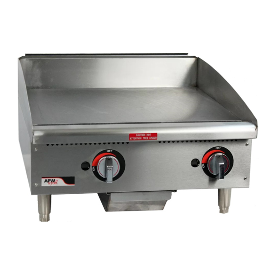
EG-24S - PERSPECTIVE VIEW
SCALE
.65
3
2
1
D
C
B
A
REV
1
1
SHEET
OF
1
Advertisement

Related Manuals for APW Wyott EG-24S


Summary of Contents for APW Wyott EG-24S
- Page 1 This manual must be read and understood by all persons using or installing this appliance. Contact your Star dealer if you have any questions concerning installation, use, or maintenance of this equipment. DO NOT DISCARD THIS MANUAL. is a registerd trademark of APW Wyott®, A Middleby Company. All rights reserved.
- Page 2 LIMITED EQUIPMENT WARRANTY WARRANTY EXCLUSIONS APW warrants to the original purchaser of new APW's products to be THE FOLLOWING WILL NOT BE COVERED UNDER WARRANTY. free from defects in material or workmanship, under normal and proper APWs’ sole obligation under this warranty is limited to either repair use and maintenance service as specified by APW and upon proper or replacement parts, subject to the additional limitations installation and start-up in accordance with the instructions...
-
Page 3: Table Of Contents
TABLE OF CONTENTS Warranty General Information and Installation Phase Diagram Daily Operation Cleaning Specifications Exploded Views Parts List... - Page 4 fields ready when you call to ensure a faster service. Using any part other than genuine APW Wyott factory supplied parts relieves the manufacturer of all liability. Due to periodic changes in designs, methods, procedures, policies, and regulations, the specifi cations contained in this document are subject to change without notice.
-
Page 5: General Information And Installation
GENERAL SAFETY INFORMATION This equipment is designed and sold for commercial use only, and is intended for use by personnel trained and experienced in its operation. This is not sold for consumer use in and around the home nor for use directly by the general public in food service locations. Before using your new equipment, read and understand all the instructions and labels associated with the unit prior to putting it into operation. -
Page 6: Phase Diagram
PHASE DIAGRAM POWER MUST BE REMOVED FROM THE UNIT BEFORE ATTEMPTING REPAIR OR SERVICE. MAKE CERTAIN TO CHECK ALL CONNECTIONS THOROUGHLY BEFORE RESTORING POWER TO THE UNIT. THE INFORMATION BELOW IS REFERENCED FROM DIAGRAM 2M-Z21072. 36 INCH MODEL 3 PHASE SINGLE PHASE FRAME FRAME... -
Page 7: Daily Operation
DAILY OPERATION TEMPERATURE CONTROL The temperature controls are combination “ON/OFF” switches and thermostats. Turning the dial knob GRIDDLE CARE automatically maintains the selected heat range. It takes very little time and effort to keep the griddle There is one thermostat for every twelve [12] inch attractive and performing at top efficiency. -
Page 8: Specifications
SPECIFICATIONS EG-24S shown 4.0 [10.0] 3.8 [9.7] 5.8 [14.8] 19.0 [48.3] Model (A) Width (B) Depth (C) Height (D) Leg Width Plate Depth Installed Weight Shipping Weight Inches (cm) Inches (cm) Inches (cm) Inches (cm) Inches (mm) lbs. (kg) lbs. (kg) EG-24S 24 (61.0) -
Page 9: Exploded Views
FRONT-PANEL AND CONTROLS RIGHT SIDE-PANELS EG-36S shown LEFT SIDE-PANELS EG-36S shown... - Page 10 BOTTOM EG-36S shown HEATING ELEMENT HARDWARE EG-36S shown REAR-ELECTRICAL BOX EG-36S shown POWER JUNCTION BOX...
-
Page 11: Parts List
Items labeled “NP” are not pictured. MODEL PART NUMBER DESCRIPTION PAGE NO G3-Z6036 DRAWER SLIDE G3-624304 GREASE CHUTE G3-Y7046 GREASE DRAWER EG-24S EG-36S G3-GD0036 PROBE TUBE ASSEMBLY EG-48S EG-24S G3-Z5952 PANEL, REAR 24 INCH EG-36S G3-Z5954 PANEL, REAR 36 INCH... - Page 12 #10-24 X 0.375 INCH MACHINE SCREW EG-48S EG-24S EG-36S 2R-8706315 KNOB, ELECTRIC THERMOSTAT EG-48S EG-24S EG-36S RM-Z15451 LABEL, APW Wyott ELECTRIC KNOB EG-48S EG-24S G3-Z15708 PANEL, FRONT 24 INCH EG-36S G3-Z15709 PANEL, FRONT 36 INCH EG-48S G3-Z15796 PANEL, FRONT 48 INCH...
- Page 13 PAGE INTENTIONALLY LEFT BLANK...
- Page 14 Printed in the U.S.A. • 2M-Z23810 • Rev - (12/16/2020) Specifications are subject to change without notice. 265 Hobson St. • Smithville, TN 37166 is a registerd trademark of APW Wyott®, A Middleby Company. All rights reserved. Telephone: (800) 527-2100...
Need help?
Do you have a question about the EG-24S and is the answer not in the manual?
Questions and answers