Advertisement
Quick Links
Advertisement

Subscribe to Our Youtube Channel
Related Manuals for StarTrac 9-3613


Summary of Contents for StarTrac 9-3613
- Page 1 CORE HEALTH & FITNESS 4-TR TREADMILLS ASSEMBLY MANUAL...
-
Page 2: Table Of Contents
TABLE OF CONTENTS IMPORTANT SAFETY INSTRUCTIONS ........................2 PRODUCT SPECIFICATIONS ........................4 PART IDENTIFICATION ........................6 ASSEMBLY ........................7 10” LCD CONSOLE ..............14 10” TOUCHSCREEN CONSOLE ..............16 SUPPORT & SERVICE ........................17 Page 1... -
Page 3: Important Safety Instructions
IMPORTANT SAFETY INSTRUCTIONS WARNING! Before using this product, it is essential to read the ENTIRE Owner’s Manual and ALL installation instructions. The Owner’s Manual describes equipment setup and instructs members on how to use correctly and safely. Read all warnings posted on the machine. Health related injuries may result from incorrect or excessive use of exercise equipment. - Page 4 Do not exceed the maximum allowable weight limit of: • 4-TR - 450 lbs. / 204 kg. Familiarize yourself with the location of the STOP buttons on the console. If you experience difficulties during the workout, pushing the STOP button will bring the machine to a stop. Lock your treadmill when not in use.
-
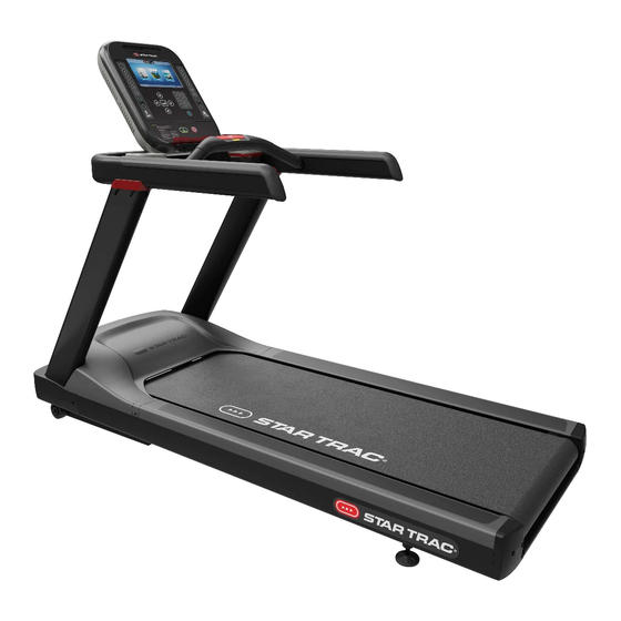
Page 5: Product Specifications
PRODUCT SPECIFICATIONS Fig. 2 15” OpenHub Console shown Desc: 4-TR Treadmill SKU: 9-3613 110V, 15AMP, UL/CSA 9-3614 220V, UL/CSA/CE Max User Unit Weight Width Length Height Belt Width Weight 60.5 21.5 0-450 lbs 0-204 kg Page 4... - Page 6 Other Consoles Fig. 3 10” Touchscreen Console Fig. 4 LCD Console Page 5...
-
Page 7: Part Identification
PART IDENTIFICATION Fig. 5 4-TR Features, 15” OpenHub Console Shown Part Part Part Console Safety Stop (Cord) Foot Front Handlebar Moving Surface Elevation Frame Heart Rate Grips Deck Motor Shroud Safety Stop (Button) Rear Roller Shroud Handrail Rear Roller Page 6... -
Page 8: Assembly
ASSEMBLY Assembly instructions cover either 10” touchscreen or LCD console. For 15” Embedded, please see the console manual 620-8816 for additional wiring and configuration information. Required Tools: • 13mm Socket • Torque Wrench • 5mm Allen Key • #2 Phillips Screwdriver •... - Page 9 3. Route the wires up through the right- side upright handrail (740-9453-XX) using chaser wire. Fig. 7 4. Install right upright handrail onto frame using a 13mm socket to secure two pieces each of the M8 x 70mm (110- 4075) and M8 x 20mm (110-4076) hex head screws.
- Page 10 6. Place the left-side beauty ring onto the left upright handrail (BE CAREFUL OF RING ORIENTATION), set the right-side beauty ring in place on the right-side upright handrail, then put the handrail weldment onto the top of the upright handrails (BE CAREFUL NOT TO PINCH WIRE BUNDLE).
- Page 11 9. Using a 13mm socket, secure the console mount (020-7924) to the handrail weldment using four (4) pieces of the M8 x 20mm hex head screws (110-4076) TORQUE TO 15-20 lb-ft /20-27 Nm. Fig. 13 10. Use a #2 phillips screwdriver to loosen the left-side screw on the front shroud cover then secure the left-side corner shroud (740-9405-XX) to the frame...
- Page 12 12. Secure the side bed shroud to the frame using one (1) piece of the M5 x 18mm screw then slide the left side bed bridge cap (740-9451-XX) into the gap between the left side bed cover and top shroud. 13.
- Page 13 16. Use a #2 phillips screwdriver to remove the small back panel (020-7927-XX) from the back console shroud (701- 0326-XX) Fig. 19 17. Set the back console shroud into position on the console mount then reattach the back panel removed in Step 16.
- Page 14 (Green/White) (Red/Black) Fig. 22 Wiring from Neck of Unit 19. Plug the three cables from Fig. 22 into the console as indicated in Fig. 23. Note: Lines E & F indicate the wiring path from the board to the rear console jacks.
-
Page 15: 10" Lcd Console
21. Plug the power cord (220-0276 OR 220-0279 ) into the power inlet. Fig. 25 22. Ensure no one is standing on the treadmill. 23. Install Console. For 10” touchscreen, skip ahead to page 16. 10” LCD CONSOLE On the numeric keypad, press and hold the keys together. - Page 16 Use the arrow keys to select “Calibration”, then press the button. Fig. 28 Press the button again and the treadmill will run both the ele- vation and speed calibrations. WARNING: Do not stand on moving surface during calibration. Fig. 29 Page 15...
-
Page 17: 10" Touchscreen Console
10” TOUCHSCREEN CONSOLE Touch the top left corner, then the center and then the top left corner again. The Service Menu will display. Tap Calibration & Setup. Fig. 30 Tap Calibration Fig. 31 Tap Calibration and the treadmill will run both the elevation and speed calibrations. -
Page 18: Support & Service
SUPPORT & SERVICE For Technical Support, Service, Parts Orders or any Customer Service needs, please contact us direct by phone, email, or through our 24 hour support site: GLOBAL SUPPORT CENTER 4400 NE 77th Avenue, Suite 300 Vancouver, WA 98662 Tel: (360) 326-4090 •... - Page 19 THIS PAGE INTENTIONALLY BLANK Page 18...
- Page 20 © 2020 CORE HEALTH & FITNESS LLC PART NUMBER 620-8653, REV E All rights reserved. Star Trac, the Star Trac logo and StairMaster are registered trademarks of Core Health & Fitness, LLC. Schwinn and Nautilus are registered trademarks of Nautilus Inc. used under license to Core Health & Fitness LLC. Throwdown is a registered trademark of Throwdown Industries, LLC.
Need help?
Do you have a question about the 9-3613 and is the answer not in the manual?
Questions and answers