
Subscribe to Our Youtube Channel
Related Manuals for Arec TP-100


Summary of Contents for Arec TP-100
- Page 1 TP-100 Auto Tracking System User Manual English AREC Inc.© All Rights Reserved 2013. l www.arec.com All information contained in this document is Proprietary...
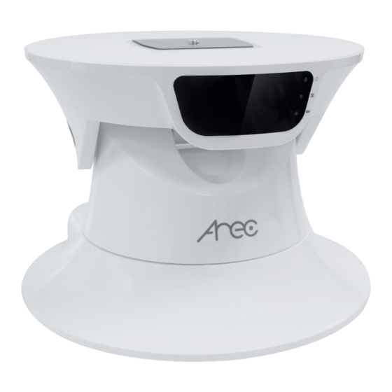
- Page 2 TP-100 User Manual Auto Tracking System Your AREC TP-100 auto Tracking System can work with different cameras for vertical and horizontal tracking. It may track shooting lecturers/target in indoor environment when accompanied with a compact IR Locator(AREC AM-500). In addition to online device setup, the AREC Auto Tracking System features both auto and manual tracking modes for even greater user conveniences.
-
Page 3: Table Of Contents
TP-100 User Manual Table of Contents 1. PRODUCT INFORMATION..................3 2.GETTING TO KNOW YOUR PRODUCT...............4 3. LIGHT INDICATORS OF YOUR TP-100..............7 4. WIRELESS MICROPHONE LOCATOR INFORMATION..........7 5. LIGHT INDICATORS OF YOUR AM-500..............8 6. HOW TO INSTALL YOUR SYSTEM................8 7. HOW TO ENABLE THE AUTO TRACKING FUNCTION? .........10 8. -
Page 4: Product Information
TP-100 User Manual 1. Product information Safety precautions Battery safety information: Keep the battery at a dry and cool environment. DO NOT dispose of your battery with household waste. Send used batteries to a specific re-cycling location. Remove your battery out of your device if you are not to use it for long time. Do the same with empty batteries as the remote controller may be damaged by leakage of current and battery liquid. - Page 5 Tilting: 60 degree (-25 ~ +35 degree ) Tracking range A circle of 2~12 meter radius (from locator to TP-100)* Via control web page (TP-100 setup page along with KS-700 online directing) Manual operation Joystick & console control via RS-485 interface...
-
Page 6: Getting To Know Your Product
C. M3 screw holes (for fixing with included screws) Rear A. TP-100 external network port B. TP-100 external power socket C. RS-485 connector D. Power and network connector for TP-100 and Cloud console * To connect to LAN or AREC KS-700 device... -
Page 7: Light Indicators Of Your Tp-100
4. Wireless microphone locator information AREC TP-100 can work with the AREC wireless microphone, an exclusive locator, for concurrent lecturing and tracking shooting. When the person wearing the microphone moves, the TP-100 would follow its movement without interruption by other moving objects. -
Page 8: How To Install Your System
The light flashes blue slowly when paired with one device successfully 6. How to install your system Your TP-100 can be ceiling mounted or wall mounted or affixed on a stand. See below for each installation method. 1.Ceiling mounted installation... - Page 9 2.Wall mounted or on a stand (1) The standard 1/4” 20 UNC and three M3 screw holes at bottom of TP-100 enable it to mount to a wall or on a stand.。 (2) Fix the hanger or stand to a wall or floor, then mount your TP-100 to the fast removal board or the screw...
-
Page 10: How To Enable The Auto Tracking Function
3. Fix your AM-500 to the target person or object properly. After your AM-500 is detected by your TP-100, its power indicator flashes, and it follows the movement of the person automatically. -
Page 11: How To Install A Network Camera
QUICK SHOE's instruction label. 3. Pull open your TP-100's QUICK SHOE lock, insert the network camera until the lock snaps back to its original position. 4. Prepare the power wire to connect your TP-100 5. -
Page 12: The Tp-100 Management Web Page
You can connect your TP-100 to a PC or notebook with standard network cable and enter the TP-100 management site via your Internet browser or connect your TP-100 to a KS-700 and enter the setup page via the KS-700 management web page. See below for details. - Page 13 IP address to the same as that of the newly found IP address of your TP-100, open up your network browser, type in the newly found IP address of your TP-100 and it should work now.
- Page 14 TP-100 User Manual (2) Click sensor setup in your KS-700 management page. (3) The search page displays. Click the Auto Tracking System tab and the Auto Tracking System information page displays.
- Page 15 TP-100 User Manual (4) Click Advance and the system login page pops up. Type the default account ID and password (admin and admin) and the Auto Tracking System management page displays.
-
Page 16: The Administrator Web Page
Validate the file name, press the Upload button to start software updating. v. The power light indicator of TP-100 flashes orange during software updating. vi. Once the update is completed, the power light stops flashing to turn to steady green and the TP-100 back to its original position. - Page 17 TP-100 User Manual 7.Installed direction: Select to install your TP-100 in upright direction (e.g. installed on a tripod) or upside down direction (e.g. ceiling mounted). Set up the upside down direction installation if your TP-100 is ceiling mounted or it may move opposite to your instruction when operating it manually.
- Page 18 TP-100 User Manual Patrol setup: 1. Preset point setting: Set up the arrow key direction control. Press the HOME key to return to the origin. 2. Coordinates of the system: Negative, "-" coordinates to the left and positive "+" the right.
- Page 19 S04: Press the arrow key once to move “S04” distance. Unit distance: S01 < S02 < S03 < S04, the greater the number is the faster the TP-100 is scanning. 2. Manual direction control panel: Press the arrow key to change direction. Press HOME key to back to the origin.
-
Page 20: How To Setup Auto Full View Function
When TP-100 cannot “see” the tracking target, the video will take useless scenes without any lecturer or teacher inside. Therefore, we could suggest users to activate auto full view function to cover this problem. This function MUST be set in AREC KS-700 Media Station web page and work with KS-700 to get a better performance. - Page 21 6. The setting completed. You could click on P01 button below to check the close-up shot and “Home” button which in the direction keys to check the full view setting. 7. Log into TP-100 administrator web page, and check if the function already activated.
-
Page 22: How To Do When You Forget The Ip Address
5. Release the button and TP-100 will restart. The power indicator would show orange which means the system turned to DHCP successfully. 6. Do the above steps again and you would change TP-100 network setting from DHCP to fixed IP (192.168.1.100) and the indicator would show green while restarting. -
Page 23: Appendix
Proper installation position of TP-100 (the best tracking distance): 4~7 meters away from the target object. * Faultless tracking: Nothing stands in between AM-500 and TP-100, e.g. the target turn around. Once the target is lost, the TP-100 can detect the target again in 3 seconds automatically. - Page 24 Assume the classroom is of width at 10m TP-100 is away from the blackboard at 4~7m You may employ the projector ceiling mount in the system installation: You may employ a projector ceiling mount in the system installation to adapt to different classroom height.
- Page 25 2.5m 2.35m 16° 1.15m 1.2m The shortest distance your TP-100 can be tracked: 1.6m 2m x cos35°=1.64m Assumptions: 1. Height of the target: 1.7m 2. AM-500 is worn at 1.2m above the ground 3.The ceiling is 2.5m high These two figures are for illustration only. The proportion may be incorrect.
- Page 26 AREC Inc.© All Rights Reserved 2013. l www.arec.com All information contained in this document is Proprietary Made in Taiwan Version:2013-9...
Need help?
Do you have a question about the TP-100 and is the answer not in the manual?
Questions and answers