Table of Contents
Advertisement
Quick Links
Operation and Parts
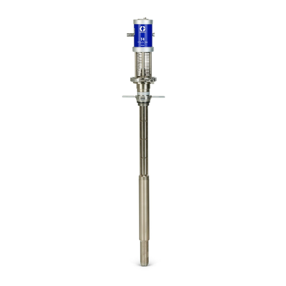
T4
3:1 Pneumatic Transfer Pump
For use with polyurethane foam, polyurea, and similar non-flammable materials. For
professional use only.
Not approved for use in European explosive atmospheres.
See page 2 for model information.
100 psi (0.69 MPa, 6.9 bar) Maximum Air Working Pressure
315 psi (2.17 MPa, 21.7 bar) Maximum Fluid Working Pressure
Important Safety Instructions
Read all warnings and instructions in this
manual before using the equipment.
Save these instructions.
3A8502A
EN
Advertisement
Table of Contents

Related Manuals for Graco 26D001


Summary of Contents for Graco 26D001
- Page 1 Operation and Parts 3A8502A 3:1 Pneumatic Transfer Pump For use with polyurethane foam, polyurea, and similar non-flammable materials. For professional use only. Not approved for use in European explosive atmospheres. See page 2 for model information. 100 psi (0.69 MPa, 6.9 bar) Maximum Air Working Pressure 315 psi (2.17 MPa, 21.7 bar) Maximum Fluid Working Pressure Important Safety Instructions Read all warnings and instructions in this...
-
Page 2: Table Of Contents
Important Isocyanate (ISO) Information ....5 Pump (26D001) ......18 Isocyanate Conditions . -
Page 3: Warnings
Warnings Warnings The following warnings are for the setup, use, grounding, maintenance, and repair of this equipment. The exclamation point symbol alerts you to a general warning and the hazard symbols refer to procedure-specific risks. When these symbols appear in the body of this manual or on warning labels, refer back to these Warnings. Product-specific hazard symbols and warnings not covered in this section may appear throughout the body of this manual where applicable. - Page 4 Warnings WARNING FIRE AND EXPLOSION HAZARD Flammable fumes, such as solvent and paint fumes, in work area can ignite or explode. Paint or solvent flowing through the equipment can cause static sparking. To help prevent fire and explosion: • Use equipment only in well-ventilated area. •...
-
Page 5: Important Isocyanate (Iso) Information
Important Isocyanate (ISO) Information Important Isocyanate (ISO) Information Isocyanates (ISO) are catalysts used in two component materials. Isocyanate Conditions Spraying or dispensing fluids that contain isocyanates creates potentially harmful mists, vapors, and atomized particulates. • Read and understand the fluid manufacturer’s warnings and Safety Data Sheets (SDSs) to know specific hazards and precautions related to isocyanates. -
Page 6: Material Self-Ignition
Important Isocyanate (ISO) Information Material Self-Ignition Moisture Sensitivity of Isocyanates Exposure to moisture (such as humidity) will cause ISO to partially cure, forming small, hard, abrasive crystals that become suspended in the fluid. Eventually a film will form on the surface and the ISO will begin to gel, Some materials may become self-igniting if applied too thick. -
Page 7: Foam Resins With 245 Fa Blowing Agents
Important Isocyanate (ISO) Information Foam Resins with 245 fa Changing Materials Blowing Agents NOTICE Some foam blowing agents will froth at temperatures Changing the material types used in your equipment above 90 °F (33 °C) when not under pressure, requires special attention to avoid equipment damage especially if agitated. -
Page 8: Typical Installation
Typical Installation Typical Installation Typical Installation without Circulation (ISO) (RES) . 1: Typical Installation without Circulation NOTE: See Typical Pump Installation, page 10, for required components. Ref. Description Ref. Description Transfer Pumps (other items purchased separately) Proportioner Agitator Transfer Pump Air Supply Lines Desiccant Dryer Waste Containers Bleed Lines... -
Page 9: Typical Installation With Circulation
Typical Installation Typical Installation with Circulation (ISO) (RES) . 2: Typical Installation with Circulation NOTE: See Typical Pump Installation, page 10, for required components. Ref. Description Proportioner Transfer Pump Air Supply Lines Fluid Supply Lines Transfer Pumps (other items purchased separately) Agitator Desiccant Dryer Circulation Lines... -
Page 10: Typical Pump Installation
Typical Installation Typical Pump Installation . 3: Typical Pump Installation Ref. Description Ref. Description Pump Fluid Inlet Pump Air Regulator Pump Air Inlet, 1/4 npt(f) Air Line Filter Pump Fluid Outlet, 3/4 npt(f) Bleed-Type Master Air Valve (required) Pressure Relief Valve (100 psi, 6.8 bar, 0.68 MPa) Fluid Drain Valve (required) Bung Adapter *Sold Separately... -
Page 11: Typical Multiple Pump Lowers Installation
Typical Installation Typical Multiple Pump Lowers Installation To Proportioner . 4: Typical Multiple Pump Lowers Installation Ref. Description Return Tube Kit Multiple Pump Lowers Fluid Kit Grounded Fluid Hose 3A8502A... -
Page 12: Installation
Installation Installation The following items are sold separately: Air compressor: Ground according to manufacturer recommendations. A bleed-type master air valve (AD) and a fluid drain valve (AE) are required in your system to help reduce Air and fluid hoses: Use only electrically conductive the risk of serious injury, including splashing fluid in hoses with a maximum of 300 ft (91 m) combined hose the eyes or on the skin, and injury from moving parts... -
Page 13: Pump Setup
Installation Pump Setup 4. Use the pump identification labels and bands provided to identify the appropriate pump for your material. 1. Connect the supplied pump air regulator (AA) to the air motor inlet (DA). 2. It is recommended to install a filter (AC) with the required bleed-type master valve (AD) and air line with a 3/8 in. -
Page 14: Operation
Operation Operation Flush Before Using Equipment Pressure Relief Procedure Follow the Pressure Relief Procedure whenever you see this symbol. To avoid fire and explosion, always ground equipment and waste container. To avoid static sparking and injury from splashing, always flush at the lowest possible pressure. -
Page 15: Changing Material Drums
Operation Changing Material Drums 4. Slide the air motor away from the pump and remove the air motor. NOTE: If the height of your ceiling or trailer prohibits the removal of the pump, the air motor and pump lower can be uncoupled. -
Page 16: Daily Startup
Operation Daily Startup Daily Shutdown 1. Turn off air supply to the pump. 1. Verify that the air regulator is set to zero. 2. Close the bleed-type master air valve (AD). 2. Open the bleed-type master air valve (AD). 3. When air pressure is bled off, set the air regulator to zero. -
Page 17: Troubleshooting
Troubleshooting Troubleshooting 1. Follow Pressure Relief Procedure, page 14, before checking or repairing pump. 2. Check all possible problems and causes before disassembling pump. Problem Cause Solution The pump fails to operate Damaged air valve Replace or service air valve (314). Damaged pilot valve Replace pilot valves (313). -
Page 18: Parts
Parts Parts Pump (26D001) Pump (26D001) Parts List Ref. Part Description Qty. 273295 PUMP, lower 273294 AIR MOTOR, T4 510490 CLAMP, pump 24Z963 REGULATOR, quick connect 25B395 ADAPTER, bung, 2 in., EZ removal 26D216 BAND, identity, res (blue) 26D216 BAND, identity, iso (red) -
Page 19: Air Motor (273294)
Parts Air Motor (273294) Apply thread adhesive. Torque to 5-10 ft-lb (6.7-13.5 N•m) Torque to 110-120 in-lb (12.4-13.5 N•m) Air Motor (273294) Parts List Ref. Part Description Qty. - - - - - MOTOR, air, 2.5 in, d pulse - - - - - ROD, tie - - - - - RING, mounting clamp, air... -
Page 20: Air Motor (273294) Continued
Parts Air Motor (273294) continued Torque to 11-13 ft-lb (15-18 N•m). Apply lubricant. Apply adhesive and then torque to 35-40 ft-lb (47.4-54.2 N•m). Torque to 95-105 in-lb (10.7-11.8 N•m). 3A8502A... - Page 21 Parts Air Motor (273294) Parts List continued Ref. Part Description Qty. Ref. Part Description Qty. 317† - - - - - RING, retaining 301† - - - - - COVER, lower, 2.5 318† - - - - - ROD, piston, air motor 302†...
-
Page 22: Air Valve (Included In Kit 24A351)
Parts Air Valve (Included in kit 24A351) Apply lubricant Air Valve Parts List Ref. Part Description Qty. Ref. Part Description Qty. 408† - - - - - PLUG, air valve, small 401‡† 124796 O-RING, 018 buna 409‡† - - - - - SEAL, u-cup, bevel lip 402‡†... -
Page 23: Accessories
Parts Accessories Grounding Clamp (not included) To ensure maximum pump performance, make sure all Part Description Qty. accessories are properly sized to meet your system 103538 CLAMP, ground requirements. Air Line Install the following accessories in the order shown in Typical Pump Installation, page 10, using adapters as necessary. - Page 24 Parts Air Line Filter and Regulator (not included) Return Tube Kit (not included) Maximum Working Pressure: 180 psi (1.3 MPa, 13 bar) Part Description Qty. Part Description Qty. 246477 KIT, carbon steel return tube 24D106 KIT, stainless steel return tube 202660 FILTER, air;...
- Page 25 Parts Swivel Fitting (not included) Air Supply Kit 246483 (not included) Part Description Qty. Ref. Description Qty. 157785 FITTING, swivel HOSE, coupled, 15 ft COUPLER, line, air VALVE, needle FITTING, line air FITTING, 1/4 npsm x 1/4 npt FITTING, tee, 1/4 in. SWIVEL, union HOSE, coupled, 4 ft Ground Wire Assembly (not included)
-
Page 26: Performance Chart
Performance Chart Performance Chart Calculate Fluid Outlet Pressure Calculate Pump Air Consumption To calculate fluid outlet pressure (psi) at a specific fluid flow (gpm) and operating air pressure (psi), use the To calculate pump air consumption (scfm) at a specific following instructions and F . -
Page 27: Pressure Conversion Chart
Performance Chart Pressure Conversion Chart Fluid Pressure Air Pressure 50 psi (3.4 bar, 0.34 MPa) 16.7 psi (1.1 bar, 0.11 MPa) 75 psi (5.1 bar, 0.51 MPa) 25.0 psi (1.7 bar, 0.17 MPa) 100 psi (6.8 bar, 0.68 MPa) 33.3 psi (2.2 bar, 0.22 MPa) 125 psi (8.6 bar, 0.86 MPa) 41.7 psi (2.8 bar, 0.28 MPa) 150 psi (10.3 bar, 1.03 MPa) -
Page 28: Dimensions
Dimensions Dimensions Ref. Dimension Measurement Overall Length 50.1 in. (127.2 cm) Pump Length 33.9 in. (86.1 cm) Air Inlet 1/4 in. npt(f) Fluid Outlet 3/4 in. npt(f) 3A8502A... -
Page 29: Recycling Or Disposal
Dimensions Recycling or Disposal End of Product Life At the end of a product’s useful life, recycle it in a responsible manner. California Proposition 65 CALIFORNIA RESIDENTS WARNING: Cancer and reproductive harm – www.P65warnings.ca.gov. 3A8502A... -
Page 30: Technical Specifications
88° C Inlet/Outlet Sizes Air inlet size 1/4-18 in. npt(f) Fluid outlet size 3/4-14 in. npt(f) Materials of Construction Wetted materials on 26D001 Carbon steel, stainless steel, PTFE Weight All models 24 lb. 10.8 kg Noise (dBa) Maximum sound pressure* 72.9 dBa @ 70 psi (0.48 MPa, 4.8 bar) -
Page 31: Notes
Notes Notes 3A8502A... -
Page 32: Graco Standard Warranty
With the exception of any special, extended, or limited warranty published by Graco, Graco will, for a period of twelve months from the date of sale, repair or replace any part of the equipment determined by Graco to be defective.
Need help?
Do you have a question about the 26D001 and is the answer not in the manual?
Questions and answers