
Related Manuals for IBA ibaPADU-D-8AI-U


Summary of Contents for IBA ibaPADU-D-8AI-U
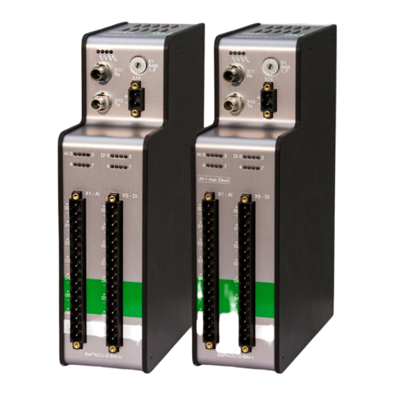
- Page 1 Manual ibaPADU-D-8AI-U/-D-8AI-I Parallel-Analog-Digital-Converter for 8 channels Manual Issue 1.4 Issue 1.4...
- Page 2 However, the information in this publication is updated regularly. Required cor- rections are contained in the following regulations or can be downloaded on the Internet. The current version is available for download on our web site http://www.iba-ag.com. Protection note Windows®...
-
Page 3: Table Of Contents
Manual Table of contents About this manual ................... 5 Target group ....................5 Notations ....................... 5 Used symbols....................6 Introduction ..................... 7 Scope of delivery..................... 9 Safety instructions ..................9 Designated use ..................... 9 Special advices ..................... 9 System requirements ..................10 Hardware .................... - Page 4 Manual ibaPADU-D-8AI-U/-D-8AI-I Technical Data ....................28 10.1 Main data ....................28 10.2 Dimension sheet ..................31 10.3 Example for FO budget calculation ............. 32 Support and contact ..................34 Issue 1.4...
-
Page 5: About This Manual
Manual About this manual This manual describes the construction, the use and the operation of the devices ibaPADU-D-8AI-U and ibaPADU-D-8AI-I. Target group This manual addresses in particular the qualified professionals who are familiar with han- dling electrical and electronic modules as well as communication and measurement tech- nology. -
Page 6: Used Symbols
Manual ibaPADU-D-8AI-U/-D-8AI-I Used symbols If safety instructions or other notes are used in this manual, they mean: The non-observance of this safety information may result in an imminent risk of death or severe injury: • By an electric shock! Due to the improper handling of software products which are coupled to input and •... -
Page 7: Introduction
Thereby, the distance between the devices can be up to 2 km. Other 32Mbit Flex-enabled iba devices can be integrated into the ring as well. For example, it is possible to use an ibaPADU-D device as an extension for an ibaPADU- S modular system, when all slots are already occupied. - Page 8 Manual ibaPADU-D-8AI-U/-D-8AI-I In brief: ibaPADU-D-8AI-U 8 digital inputs and 8 analog voltage inputs Input level ±2.5 V ,±10 V, ±24 V or ±60 V Input impedance 100 kΩ or 1 MΩ ibaPADU-D-8AI-I 8 digital inputs and 8 analog current inputs ...
-
Page 9: Scope Of Delivery
Automation of industrial systems Measurement data logging and analysis Applications of software products (e.g. ibaPDA) or hardware products of the iba AG. The device is only to be applied as shown in the Technical Data chapter. Special advices... -
Page 10: System Requirements
1 free PCI/PCIe slot 512 MB RAM 4 GB free memory on the hard drive for measurement values On our Website http://www.iba-ag.com, you find suitable industry-type and desk- top-type PC systems. At least one fiber optic card of ibaFOB-D type ... -
Page 11: Mounting And Dismounting
Manual Mounting and dismounting Mounting 1. Locate the DIN rail mounting clip on the rear side of the device. Slowly push down and in so that the bottom part of the mounting clips snaps onto the bottom part of the rail and firmly fixes the device to the DIN rail. -
Page 12: Device Description
Manual ibaPADU-D-8AI-U/-D-8AI-I Device description Device view 7.1.1 Front view Operating state display Rotary switch S1 FO input (RX) X11 Power supply terminal X14 FO output (TX) X10 Status LEDs of analog channels AI 0...7 Status LEDs of digital channels DI 0..7... -
Page 13: Indicating Elements
( e. g. rotary switch S1 = 0) 32Mbit Flex signal detected Error Blinking Configuration error ( e. g. rotary switch S1 = 0) Hardware error Status of analog inputs ibaPADU-D-8AI-U Sta- Description (approx. values) Range ±2.5 V Range ±10 V Range ±24 V Range ±60 V... -
Page 14: Connections
The device requires an external DC 24 V ±10% power supply (unregulated). The oper- ating voltage should be run through the provided 2-pin Phoenix threaded coupling con- nector. If desired, you can order DIN rails or plug-in power supply units from iba. 7.3.3 Analog / digital inputs 7.3.3.1... - Page 15 > 2 ms. 7.3.3.2 Operation modes of analog inputs The different input ranges and input impedances (ibaPADU-D-8AI-U only) are configured for each channel in the I/O Manager of ibaPDA. ibaPADU-D-8AI-U Possible input ranges: ±2.5 V, ±10 V, ±24 V or ±60 V ...
- Page 16 Manual ibaPADU-D-8AI-U/-D-8AI-I Figure 4: Debounce filter: „Stretch rising edge“ „Stretch falling edge“ With the first falling edge, the output signal (green) switches to logical 0 and keeps this value for the defined debounce time. Thereafter, the channel is transparent again and waits for the next falling edge.
- Page 17 Manual Figure 7: Debounce filter: „Delay both edges“ 7.3.3.4 Connection diagram / pin assignment It is possible to connect 8 analog input signals and 8 digital input signals, each bipolar and electrical isolated. Each channel is connected by means of two-wire connection. Due to the reverse polarity protection, the measuring signal is indicated logically correct, even if the connection is polarity-reversed.
-
Page 18: Grounding Screw X29
Manual ibaPADU-D-8AI-U/-D-8AI-I Pin assignment X1 Pin... Connection X5 Pin... Connection Analog input 00 + Digital input 00 + Analog input 00 − Digital input 00 − Analog input 01 + Digital input 01 + Analog input 01 − Digital input 01 −... -
Page 19: Operating Elements
Manual Operating elements 7.4.1 Rotary switch S1 With 32Mbit Flex you can group up to 15 modular systems to a ring topology. The devices are addressed via the S1 rotary switch. Device number in the Position of rotary switch S1... -
Page 20: System Integration
Other 32Mbit Flex-enabled iba devices can be integrated into the ring as well. For exam- ple, it is possible to use an ibaPADU-D device as an extension for an ibaPADU-S modular system, when all slots are already occupied. -
Page 21: Configuration In Ibapda
1. Start the ibaPDA client and open the I/O Manager. 2. Choose the correct ibaFOB-D input card in the signal tree (on the left hand side) and mark the link ibaPADU-D-8AI-U is connected to. Right-click on the link and choose “Autodetect”. -
Page 22: General" Tab
Manual ibaPADU-D-8AI-U/-D-8AI-I 9.1.1 „General“ tab Figure 10: ibaPADU-D-8AI-U – „General“ tab Basic Module type (information only) Indicates the type of the current module Locked A module can be locked to avoid unintentional or unauthorized changing of the module settings. -
Page 23: Analog" Tab
<OK> or <Apply> of the I/O Manager. 9.1.2 „Analog“ tab Figure 11: ibaPADU-D-8AI-U – „Analog“ tab Name Assign a meaningful name to each signal and you can enter additionally two com- ments when clicking on the symbol in the field “Name”. - Page 24 Manual ibaPADU-D-8AI-U/-D-8AI-I Impedance Select an input impedance from the dropdown menu for this channel. Important note An impedance of 1 MΩ together with an input range of ±2.5 V is not supported. If this combination is selected, an error message will be displayed while validating the configu- ration.
-
Page 25: Digital" Tab
Manual 9.1.3 „Digital“ tab Figure 12: ibaPADU-D-8AI-U – „Digital“ tab Name, Active, Actual, see “Analog” tab. Debounce filter In the dropdown menu, you can choose the operating mode for the debounce filter. You have got the following settings at your disposal: Off, stretch rising edge, stretch falling edge, stretch both edges, delay both edges, see chapter 7.3.3.3... -
Page 26: Diagnostics" Tab
In order to avoid this error signal, the channel may be deactivated. The error signal will then also be deactivated. 9.1.4 „Diagnostics“ tab Figure 13: ibaPADU-D-8AI-U – „Diagnostics“ tab Here, you find information about the hardware version, firmware version, FPGA version and the serial number. Write firmware Using this button you can install a firmware update. - Page 27 Manual After the reset the following message appears and the device will be automatically rebooted. Restart device Using this button the device is restarted after having confirmed the following re- quest with <Yes>. Then you will receive the following message:...
-
Page 28: Technical Data
Manual ibaPADU-D-8AI-U/-D-8AI-I Technical Data 10.1 Main data Short description Name ibaPADU-D-8AI-U ibaPADU-D-8AI-I Description Input module with 8 digital in- Input module with 8 digital in- puts and 8 analog voltage puts and 8 analog current inputs inputs Order number 10.100100 10.100110... - Page 29 Manual Connector type 1 x 16-pin multi-pin connector; clamp-type terminal (0.2 mm² to 2.5 mm²), screw connection, included in delivery ibaNet interface Number Design Fiber optic cable ibaNet protocol 32Mbit Flex Allows the simultaneous connection of up to 15 devices in a fi-...
- Page 30 47 CFR § 2.1077 Compliance Information Unique Identifier: 10.100100 ibaPADU-D-8AI-U 10.100110 ibaPADU-D-8AI-I Responsible Party - U.S. Contact Information iba America, LLC 370 Winkler Drive, Suite C Alpharetta, Georgia 30004 (770) 886-2318-102 www.iba-america.com FCC Compliance Statement This device complies with Part 15 of the FCC Rules. Operation is subject to the following two conditions: (1) This device may not cause harmful interference, and (2) this device must ac- cept any interference received, including interference that may cause undesired operation.
-
Page 31: Dimension Sheet
Manual 10.2 Dimension sheet (Dimensions given in mm) Figure 14: Dimension sheet (Dimensions given in mm) Figure 15: Dimension sheet with cables Issue 1.4... -
Page 32: Example For Fo Budget Calculation
Manual ibaPADU-D-8AI-U/-D-8AI-I 10.3 Example for FO budget calculation As an example, an FO connection from an ibaFOB-io-Dexp card (FO transmitter) to an ibaBM-PN device (FO receiver) is used. Figure 16: Example: simple connection for FO budget calculation The example refers to a point-to-point connection with an FO cable of type 62.5/125 µm. - Page 33 Manual Equation for calculating the FO budget (A Budget ���� = |(���� − ���� ������������������������ ���� ���������������� ���� �������� ���� �������������������� = sensitivity of FO receiving interface Receiver = output power of FO transmitting interface Sender Equation for calculating the fiber optic cable length (l ����...
-
Page 34: Support And Contact
Mailing address iba AG Postbox 1828 D-90708 Fuerth Germany Delivery address iba AG Gebhardtstrasse 10 D-90762 Fuerth Germany Regional and Worldwide For contact data of your regional iba office or representative please refer to our web site www.iba-ag.com. Issue 1.4...
Need help?
Do you have a question about the ibaPADU-D-8AI-U and is the answer not in the manual?
Questions and answers