
Related Manuals for PolarPlus Win-MPPT Series


Summary of Contents for PolarPlus Win-MPPT Series
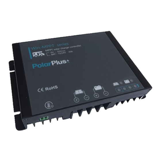
- Page 1 PolarPlus MPPT Solar Controller 12/24V, 260/520W User Manual CE, Rohs, ISO9001:2015 Subject to change without notice!
-
Page 2: Table Of Contents
Contents Safety instructions and waiver of liability ........................2 Safety Instructions ..................................2 1.2 Liability Exclusion..................................2 Pruduct Overview ..................................3 2.1 MPPT ......................................3 2.2 MPPT-Four Charging Stage ..............................4 Dimensions .....................................5 Structure & Accessory ................................6 Installation ......................................7 5.1 Installation Notes..................................7 5.2 Mounting Location Requirements............................7 5.3 Wiring Specifications................................8 5.4 Connection....................................8 5.5 Grounding.....................................8... -
Page 3: Safety Instructions And Waiver Of Liability
Dear Clients, Thanks for selecting the Win series solar controller. Please take the time to read this user manual, this will help you to make full use of many advantages the controller can provide your solar system. This manual gives important recommendations for installing and using and so on. -
Page 4: Pruduct Overview
2,Over view Win series solar controller is based on an advanced maximum power point tracking (MPPT) technology developed, dedicated to the solar system, the controller conversion efficiency up to 98%. The controller can rapidly track the maximum power point(MPP) of PV array to obtain the maximum energy of the panel, especially in case of a clouded sky, when light intensity is changing continuously, an ultra fast MPPT controller will improve energy harvest by up to 30% compared to PWM charge controllers. -
Page 5: Mppt-Four Charging Stage
An Advantage Over Traditional Controllers Traditional controllers connect the solar module directly to the battery when recharging. This requires that the solar module operate in a voltage range that is usually below the module's Vmp. In a 12 Volt system for example, the battery voltage may range from 10.8-15 Vdc,but the module's Vmp is typically around 16 or 17V. -
Page 6: Dimensions
MPPT Charge In this stage, the battery voltage has not yet reached boost voltage and 100% of available solar power is used to recharge the battery. Boost Charge When the battery has recharged to the Boost voltage setpoint, constant-voltage regulation is used to prevent heating and excessive battery gassing. -
Page 7: Structure & Accessory
4,Structure & Accessor y ①Aluminum case —dissipate controller heat, Internal protection. ②Temperature Sensor Port —Collect temperature information. Temperature compensation. ③Solar module terminals —Connected solar modules. ④Battery Terminals —Connect the battery. ② ⑤ ④ ③ ⑤LED Display —Display the status of the controller. ①... -
Page 8: Installation
5,Installation Please read all instructions and precautions in the manual before installing. 5.1 Installation Notes ⑴The solar charge controller may only be used in PV systems in accordance with this user manual and the specifications of other modules manufacturers. No energy source other than a solar generator may be connected to the solar charge controller. -
Page 9: Wiring Specifications
5.3 Wiring Specifications Wiring and installation methods must comply with national and local electrical specifications. The wiring specifications of the solar, battery must be selected according to rated currents, and see the following table for wiring specifications: Rated charging current Solar wire diameter(mm²/AWG) Batter y wire diameter(mm²/AWG) 5/10... -
Page 10: Bluetooth
6.Bluetooth 6.1 Bluetooth Communication Bluetooth communication has the following characteristics: 1.Support Android mobile phone APP. 2.Realize wireless monitoring function of solar controller. 3.Use high performance, ultra-low power consumption Bluetooth dedicated chip. 4.Adopt Bluetooth 4.2 and BLE technology. 5.communication distance up to 10m. Refer to Bluetooth APP instructions for detailed operation of mobile APP. -
Page 11: Led Indications, Protections And Maintenance
7, LED indications, Protections and Maintenance 7. 1 LED Display Solar LED Batter y LED Batter y Capacity LED Soc1 Soc2 Soc3 Soc4 Function Status Solar panel is correctly connected, but not charged MPPT charging Fast Flash(0.1s/0.1s) Solar LED Flash( 0.5s/0.5s) Equal or Boost charging (Red) Float charging... -
Page 12: Protection
7.3 Protection Protection Description The controller will limit charging power in rated charge power. PV Over Current An over-sized PV array will not operate at maximum power point. When PV short circuit occurs, the controller will stop charging. PV Short Circuit Remove it to start normal operation. -
Page 13: Technical Data
8, Technical Data Item P20LWMBT System voltage 12/24V automatical recognization Max charging current MPPT charging voltage before boost or equalization charging stage Boost voltage 14.0~14.8V/28.0~29.6V(default:14.5/29.0V@25℃ ) Equalization voltage 14.0~15.0V/28.0~30.0V(default:14.8/29.6V@25℃ ) 13.0~14.5V/26.0~29.0V(default:13.7/27.4V@25℃ ) Float voltage 10.8~11.8V/21.6~23.6V(default: 11.2/22.4V) Low voltage disconnect Batter y Low voltage reconnect 11.4~12.8V/22.8~25.6V(default: 12.0/24.0V) Parame-...
Need help?
Do you have a question about the Win-MPPT Series and is the answer not in the manual?
Questions and answers