
Related Manuals for Keithley KUSB-3116

Summary of Contents for Keithley KUSB-3116
- Page 1 KUSB-3116 Getting Started Manual KUSB3116-903-01 Rev. A / January 2005 G R E A T E R M E A S U R E C O N F I D E N C E...
- Page 2 WARRANTY Keithley Instruments, Inc. warrants this product to be free from defects in material and workmanship for a period of 3 years from date of shipment. Keithley Instruments, Inc. warrants the following items for 90 days from the date of shipment: probes, cables, rechargeable batteries, diskettes, and documentation.
- Page 3 KUSB-3116 Getting Started Manual ©2005, Keithley Instruments, Inc. All rights reserved. First Printing, January 2005 Cleveland, Ohio, U.S.A. Document Number: KUSB3116-903-01A Rev. A...
- Page 4 Revision of the manual. Each new Revision includes a revised copy of this print history page. Revision A (Document Number KUSB3116-903-01A)..............January 2005 All Keithley product names are trademarks or registered trademarks of Keithley Instruments, Inc. Other brand and product names are trademarks or registered trademarks of their respective holders.
- Page 5 Keithley products are designed for use with electrical signals that The instrument and accessories must be used in accordance with its are rated Measurement Category I and Measurement Category II, as...
- Page 6 Keithley Instru- symbol on an instrument indicates that the user should re- ments. Standard fuses, with applicable national safety approvals, fer to the operating instructions located in the manual.
-
Page 7: Table Of Contents
Table of Contents About this Manual ........Intended Audience. - Page 8 Contents Wiring Methods........Wiring Signals to the BNC Connectors ... . . Wiring Signals to the D-Sub Connectors on the BNC Connection Box .
- Page 9 Contents Performing a Single-Value Digital Input Operation ..Performing a Single-Value Digital Output Operation ..Performing a Frequency Measurement Operation..Performing a Pulse Output Operation....Appendix A: Ground, Power, and Isolation Connections .
- Page 10 Contents...
-
Page 11: About This Manual
About this Manual This manual describes how to install and set up your KUSB-3116 module and device driver, and verify that your module is working properly. Intended Audience This document is intended for engineers, scientists, technicians, or others responsible for installing and setting up a KUSB-3116 module to perform data acquisition operations. -
Page 12: Conventions Used In This Manual
Refer to the following documents for more information on using the KUSB-3116 module: • KUSB-3116 User’s Manual, included on the CD provided with the KUSB-3116 module. This manual describes the features of the KUSB-3116 module and the device driver in detail. -
Page 13: Where To Get Help
• Microsoft Windows 2000 or Windows XP documentation. • USB web site (http://www.usb.org). Where To Get Help Should you run into problems installing or using your KUSB-3116 module, please call the Keithley Technical Support Department. xiii... - Page 14 About this Manual...
-
Page 15: Chapter 1: Overview
Overview Hardware Features........Supported Software . -
Page 16: Hardware Features
Chapter 1 Hardware Features The KUSB-3116 is a high-performance, multifunction data acquisition modules for the USB (Ver. 2.0 or Ver. 1.1) bus. The key hardware features of the module is as follows: • Installed in a metal BNC box to provide easy connections. - Page 17 Overview • Digital I/O subsystem: − One digital input port, consisting of 16 digital input lines. You can program any of the first eight digital input lines to perform interrupt-on-change operations. You can read the value of the digital input port using the analog input channel-gain list.
-
Page 18: Supported Software
Chapter 1 Supported Software The KUSB-3116 software, which is shipped on the CD provided with the module, includes the following software components: • Device Driver − This software must be installed and loaded before you can use a KUSB-3116 module with any of the supported software packages or utilities. -
Page 19: Getting Started Procedure
The flow diagram shown in Figure 1 illustrates the steps needed to get started using the KUSB-3116 module. This diagram is repeated in each chapter; the shaded area in the diagram shows you where you are in the getting started procedure. - Page 20 Chapter 1...
-
Page 21: Chapter 2: Preparing To Use A Module
Preparing to Use a Module Unpacking ..........Checking the System Requirements . - Page 22 Chapter 2 Prepare to Use the Module (this chapter) Set Up and Install the Module (see Chapter 3 starting on page Wire Signals (see Chapter 4 starting on page Verify the Operation of the Module (see Chapter 5 starting on page...
-
Page 23: Unpacking
• KUSB-3116 BNC module, • USB cable, • Power supply, • Keithley CD. If an item is missing or damaged, contact Keithley Technical Support. Once you have unpacked your module, check the system requirements, as described in the next section. -
Page 24: Checking The System Requirements
Chapter 2 Checking the System Requirements For reliable operation, your KUSB-3116 module requires the following: • PC with Pentium 233 MHz (or higher) processor. • Windows 2000 or Windows XP (Professional Edition) operating system. For USB Ver. 2.0 support, make sure that you install Service Pack 1 (for Windows XP) or Service Pack 4 (for Windows 2000). -
Page 25: Installing The Software
To install the driver software, Data Acq SDK, DTx-EZ, and the Quick Data Acq software, perform the following steps: Insert the Keithley CD into your CD-ROM drive. Click Start from the Task Bar, then click Run. The Run dialog box appears. - Page 26 Chapter 2...
-
Page 27: Chapter 3: Setting Up And Installing A Module
Setting Up and Installing a Module Applying Power to the Module ......Configuring the Device Driver......Attaching Modules to the Computer. - Page 28 (this chapter) Wire Signals to the BNC Connection Box (see Chapter 4 starting on page Verify the Operation of the Module (see Chapter 5 starting on page Note: The KUSB-3116 module is factory-calibrated and requires no further adjustment prior to installation.
-
Page 29: Applying Power To The Module
Setting Up and Installing a Module Applying Power to the Module The KUSB-3116 module is shipped with a +5V power supply and cable. To apply power to the KUSB-3116 module, perform the following steps: Connect the +5 V power supply to the power connector on the KUSB-3116 module. -
Page 30: Configuring The Device Driver
Chapter 3 Configuring the Device Driver To configure the device driver for the KUSB-3116 module, perform the following steps: If you have not already done so, power up the host computer and all peripherals. From the Windows Start menu, select Settings|Control Panel. - Page 31 Setting Up and Installing a Module 10. Repeat steps 4 to 8 for the other modules that you want to configure. 11. Close the Data Acquisition Control Panel dialog box. Continue by connecting the KUSB-3116 module to the computer, as described in the next section.
-
Page 32: Attaching Modules To The Computer
Connecting One or Two Modules To connect one or two KUSB-3116 modules to a USB port of the computer, perform the following steps: Make sure that you have attached a power supply to the module. - Page 33 CD that contains the driver files, then click Next. Click Next. Click Finish. A New Hardware Found dialog box appears indicating that Windows is installing the driver for the USB module. Repeat the steps 1 to 3 to attach another KUSB-3116 module to the host computer, if desired.
-
Page 34: Connecting Multiple Modules Using An Expansion Hub
Make sure that you have attached a power supply to the module. Attach one end of the USB cable to the KUSB-3116 module and the other end of the USB cable to an expansion hub. Connect the power supply for the expansion hub to an external power supply. - Page 35 Module Module USB Cables Figure 4: Attaching Multiple KUSB-3116 Modules Using Expansion Hubs Click the option to search for the driver, then click Next. Click the option to specify the location, browse to the location on the CD that contains the driver files, then click Next.
- Page 36 Chapter 3 10. Repeat steps 1 to 3 until you have attached the number of expansion hubs (up to five) and modules (up to four per hub) that you require. The operating system automatically detects the USB devices as they are installed.
-
Page 37: Chapter 4: Wiring Signals
Wiring Signals Preparing to Wire Signals ....... . Connecting Analog Input Signals ......Connecting Analog Output Signals. - Page 38 Chapter 4 Prepare to Use a Module (see Chapter 2 starting on page Set Up and Install the Module (see Chapter 3 starting on page Wire Signals (this chapter) Verify the Operation of the Module (see Chapter 5 starting on page...
-
Page 39: Preparing To Wire Signals
Wiring Signals Preparing to Wire Signals CAUTION: To avoid electrostatic sensitivity, it is recommended that you unplug your KUSB-3116 module from the computer before wiring signals. This section provides recommendations and information about wiring signals to the KUSB-3116 module. Wiring Recommendations... -
Page 40: Wiring Methods
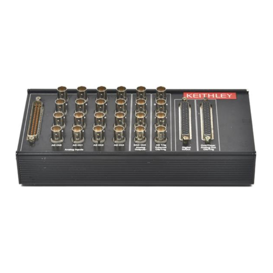
AD Ch2 AD Ch3 DAC Ch3 Figure 5: KUSB-3116 Module You can wire signals to the KUSB-3116 module in one of the following ways: • Analog input signals – You can wire analog input signals in one of the following ways: −... - Page 41 • Counter/timer signals – To wire counter/timer signals, you must use the appropriate pins on the C\T, DAC, Clk, Trig connector. Refer to Appendix A in the KUSB-3116 User’s Manual for information about the required mating connectors. • External A/D clock or trigger signal – You can wire external clock/trigger signals in one of the following ways: −...
-
Page 42: Wiring Signals To The Bnc Connectors
Connection Box If you do not want to use the BNC connectors or if you want to connect digital I/O or counter/timer signals to the KUSB-3116 module, you can use the 37-pin, D-sub connectors. These connectors are described in the following sections. - Page 43 Wiring Signals Table 1: Analog Input Connector Pin Assignments (cont.) Assignment Signal Description Assignment Signal Description Analog Input 10 Analog Input 11 Analog Input 12 Analog Input 13 Analog Input 14 Analog Input 15 Amplifier Low +5 V Analog Chassis Ground Analog Input 0 Return/ Analog In 8 Analog Input 1 Return/...
-
Page 44: Digital In/Out Connector
Chapter 4 Digital In/Out Connector The Digital In/Out connector allows you to access the digital I/O signals. Table 2 lists the pin assignments for the Digital In/Out connector. Table 2: Digital In/Out Connector Pin Assignments Assignment Signal Description Assignment Signal Description Digital Input 0 Digital Input 1 Digital Input 2... -
Page 45: C/T, Dac, Clk, Trig Connector
Wiring Signals Table 2: Digital In/Out Connector Pin Assignments (cont.) Assignment Signal Description Assignment Signal Description Digital Output 13 Digital Output 14 Digital Output 15 Dynamic Digital Output Digital Ground C/T, DAC, Clk, Trig Connector The C/T, DAC, Clk, Trig connector allows you to access the counter/timer, analog output, external clock, and external trigger signals. - Page 46 Chapter 4 Table 3: C/T, DAC, Clk, Trig Connector (cont.) Assignment Signal Description Assignment Signal Description Analog Output 1 Return Analog Output 2 Return Analog Output 3 Return Digital Ground External DAC Trigger External ADC Trigger Digital Ground Counter 0 Gate Digital Ground Counter 1 Gate Digital Ground...
-
Page 47: Connecting Analog Input Signals
Wiring Signals Connecting Analog Input Signals The KUSB-3116 module supports both voltage and current loop inputs. You can connect analog input signals to the module in the following configurations: • Single-ended − Choose this configuration when you want to measure high-level signals, noise is not significant, the source of the input is close to the module, and all the input signals are referred to the same common ground. -
Page 48: Connecting Single-Ended Voltage Inputs
Refer to page 16 for more information. Figure 6 shows how to connect single-ended voltage inputs (channels 0 and 1, in this case) to the BNC connectors on the KUSB-3116 module. KUSB-3116 Module Analog Input Analog In 0 Signal... -
Page 49: Connecting Pseudo-Differential Voltage Inputs
Figure 7: Connecting Single-Ended Inputs to a Screw Terminal Panel Connecting Pseudo-Differential Voltage Inputs Figure 8 shows how to connect pseudo-differential voltage inputs (channels 0 and 1, in this case) to the BNC connectors on the KUSB-3116 module. KUSB-3116 Module Analog Input Analog In 0 Signal... - Page 50 Chapter 4 Figure 9 shows how to connect pseudo-differential voltage inputs (channels 0 and 1, in this case) using your own cable/screw terminal panel. Screw Terminal Panel Signal Source − Analog In 0 Vsource 0 − Analog In 1 Vsource 1 Amp Low (internally connected to Analog Ground) Analog Ground...
-
Page 51: Connecting Differential Voltage Inputs
Wiring Signals Connecting Differential Voltage Inputs Figure 10 shows how to connect differential voltage inputs (channels 0 and 1, in this case) to the BNC connectors on a KUSB-3116 module. KUSB-3116 Module Analog Input Analog In 0 Signal Source Analog In 1... - Page 52 Chapter 4 Figure 11B illustrates how to connect a nonfloating signal source to your own screw terminal panel using differential inputs. In this case, the signal source itself provides the bias return path; therefore, you do not need to provide bias return resistance through software. is the signal source resistance while R is the resistance required to balance the bridge.
- Page 53 Wiring Signals Note that since they measure the difference between the signals at the high (+) and low (− ) inputs, differential connections usually cancel any common-mode voltages, leaving only the signal. However, if you are using a grounded signal source and ground loop problems arise, connect the differential signals as shown as Figure 12.
-
Page 54: Connecting Current Loop Inputs
Chapter 4 Connecting Current Loop Inputs Note: You cannot connect a current loop input using the BNC connectors. Figure 13 shows how to connect a current loop input (channel 0, in this case) to your own screw terminal panel. 4 to 20 mA Screw Terminal Panel Analog Input 0 User-installed resistor... -
Page 55: Connecting Analog Output Signals
Wiring Signals Connecting Analog Output Signals Figure 14 shows how to connect an analog output voltage signal (channel 0, in this case) to the BNC connectors on the KUSB-3116 module. KUSB-3116 Module DAC0 DACClock Analog Out 0 Load DAC1 ADClock... -
Page 56: Connecting Digital I/O Signals
Chapter 4 Connecting Digital I/O Signals Figure 16 shows how to connect digital input signals (lines 0 and 1, in this case) to your own screw terminal panel. Screw Terminal Panel Digital Input 0 Digital Input 1 TTL Inputs Digital Ground Figure 16: Connecting Digital Inputs to a Screw Terminal Panel Figure 17 shows how to connect a digital output (line 0, in this case) -
Page 57: Connecting Counter/Timer Signals
• Edge-to-edge measurement, and • Pulse output (continuous, one-shot, and repetitive one-shot). This section describes how to connect counter/timer signals. Refer to the KUSB-3116 User’s Manual for more information about using the counter/timers. Connecting Signals for Event Counting Operations Figure 18... - Page 58 Chapter 4 Screw Terminal Panel Counter 0 Clock Counter 0 Gate External Gating Switch Signal Source Digital Ground Digital Ground Figure 18: Connecting Counter/Timer Signals to a Screw Terminal Panel for an Event Counting Operation Using an External Gate Figure 19 shows how to connect counter/timer signals either to your own screw terminal panel to perform an event counting operation on counter/timer 0 without using a gate.
-
Page 59: Connecting Signals For Up/Down Counting Operations
Wiring Signals Connecting Signals for Up/Down Counting Operations Figure 20 shows how to connect counter/timer signals to your own screw terminal panel to perform an up/down counting operation on counter/timer 0. The counter keeps track of the number of rising edges that occur on the Counter 0 Clock input. -
Page 60: Connecting Signals For Frequency Measurement Operations
Chapter 4 Connecting Signals for Frequency Measurement Operations One way to measure frequency is to use the same wiring as a standard event counting application that does not use a gate (see Figure 19 page 44), then use the Windows timer to determine the duration of the frequency measurement. -
Page 61: Connecting Signals For Period/Pulse Width Measurement Operations
0. You specify the active pulse (high or low) in software. The pulse width is the percentage of the total pulse period that is active. Refer to the KUSB-3116 User’s Manual for more information about pulse periods and pulse widths. -
Page 62: Connecting Signals For Edge-To-Edge Measurement Operations
Counter 0 Clock signal) and the stop edge (in this case, a falling edge on the Counter 0 Gate signal). You specify the start edge and the stop edge in software. Refer to the KUSB-3116 User’s Manual for more information. Screw Terminal Panel Counter 0 Clock... -
Page 63: Connecting Signals For Pulse Output Operations
Wiring Signals Connecting Signals for Pulse Output Operations Figure 24 shows how to connect counter/timer signals to your own screw terminal panel to perform a pulse output operation on counter/timer 0; in this example, an external gate is used. Screw Terminal Panel Counter 0 Out Heater External... - Page 64 Chapter 4...
-
Page 65: Chapter 5: Verifying The Operation Of A Module
Verifying the Operation of a Module Overview ..........Running the Quick Data Acq Application . - Page 66 Chapter 5 Prepare to Use a Module (see Chapter 2 starting on page Set Up and Install the Module (see Chapter 3 starting on page Wire Signals to the BNC Connection Box (see Chapter 4 starting on page Verify the Operation of the Module (this chapter)
-
Page 67: Overview
Verifying the Operation of a Module Overview You can verify the operation of a KUSB-3116 module using the Quick Data Acq application. Quick Data Acq allows you to perform the following operations: • Acquire data from a single analog input channel or digital input port;... -
Page 68: Running The Quick Data Acq Application
To verify that the module can read a single analog input value, perform the following steps: Connect a voltage source, such as a function generator, to analog input channel 0 (differential mode) on the KUSB-3116 module. Refer to page 37 for an example of how to connect a differential analog input. -
Page 69: Performing A Single-Value Analog Output Operation
Click the Control menu. Click Single Analog Output. Select the appropriate KUSB-3116 module from the Board list box. In the Channel list box, select analog output channel 0. In the Range list box, select the output range of DAC0. The default is ±10 V. -
Page 70: Performing A Continuous Analog Input Operation
To verify that the module can perform a continuous analog input operation, perform the following steps: Connect known voltage sources, such as the outputs of a function generator, to analog input channels 0 and 1 on the KUSB-3116 module (differential mode). Refer to page 37 for an example of how to connect a differential analog input. -
Page 71: Performing A Single-Value Digital Input Operation
Performing a Single-Value Digital Input Operation To verify that the module can read a single digital input value, perform the following steps: Connect a digital input to digital input line 0 on the KUSB-3116 module. Refer to page 42 for an example of how to connect a digital input. -
Page 72: Performing A Single-Value Digital Output Operation
Chapter 5 Performing a Single-Value Digital Output Operation Note: Although the KUSB-3116 module contains 16 digital output lines, the Quick Data Acq application allows you to perform a digital output operation on the lower eight digital output lines (lines 0 to 7) only. -
Page 73: Performing A Frequency Measurement Operation
Note: The Quick Data Acq application works only with counter/timer 0. Click the Acquisition menu. Click Measure Frequency. Select the appropriate KUSB-3116 module from the Board list box. In the Count Duration text box, enter the number of seconds during which events will be counted. -
Page 74: Performing A Pulse Output Operation
Performing a Pulse Output Operation To verify that the module can perform a pulse output operation, perform the following steps: Connect a scope to counter/timer 0 on the KUSB-3116 module. Refer to page 49 for an example of how to connect a scope (a pulse output) to counter/timer 0. -
Page 75: Appendix A: Ground, Power, And Isolation Connections
Ground, Power, and Isolation Connections... - Page 76 Appendix A Figure 25 illustrates how ground, power, and isolation are connected internally on a KUSB-3116 module. +5 V +5 V +5 V DGND Earth GND +5 V USB; used for initialization only, not for power. USB Interface Interface Power...
- Page 77 Ground, Power, and Isolation Connections Keep the following in mind: • Earth ground on the KUSB-3116 module is not connected to DGND or AGND. • Earth ground is connected to the aluminum case of the BNC connection box. • You should connect earth ground to the power supply earth.
- Page 78 Appendix A...
-
Page 79: Index
Index analog inputs cables, USB current loops configuring the device driver differential configuration connecting signals pseudo-differential configuration analog outputs single-ended configuration current loop analog inputs wiring differential analog inputs analog outputs digital inputs and outputs applet, Open Layers Control Panel edge-to-edge measurement application wiring event counting... - Page 80 Index current loop inputs installing the software isolation DataAcq SDK device driver J2 connector pin assignments differential inputs Digital In/Out connector pin assignments LEDs digital inputs digital outputs DT-LV Link DTx-EZ online help Open Layers Control Panel applet output pulses edge-to-edge measurement, wiring event counting, wiring period measurement, wiring...
- Page 81 Index requirements running the Quick Data Acq application single-ended inputs software supported system requirements unpacking up-down counting, wiring USB cable wiring signals analog outputs current loop analog inputs differential analog inputs digital inputs and outputs edge-to-edge measurement event counting frequency measurement methods period measurement preparing...
- Page 82 Index...
- Page 83 M E A S U R E C O N F I D E N C E Keithley Instruments, Inc. Corporate Headquarters • 28775 Aurora Road • Cleveland, Ohio 44139 • 440-248-0400 • Fax: 440-248-6168 • 1-888-KEITHLEY (534-8453) • www.keithley.com 12/04...
Need help?
Do you have a question about the KUSB-3116 and is the answer not in the manual?
Questions and answers