Table of Contents
Advertisement
Available languages
Available languages
Quick Links
Advertisement
Chapters
Table of Contents

Subscribe to Our Youtube Channel
Related Manuals for Mopedia MP370


Summary of Contents for Mopedia MP370
- Page 1 LETTI DEGENZA 3 SNODI ELETTRICO MANUALE DI ISTRUZIONI...
-
Page 2: Table Of Contents
7.1 Struttura letto MP370 (letto degenza 3 snodi elettrico mod. GERANIO) ....pag. 5 7.2 Kit elettrico per MP370 (letto degenza 3 snodi elettrico mod. GERANIO) ....pag. 5 7.3 Struttura letto MP380 (letto degenza 3 snodi elettrico elevabile mod. GERBERA) pag. 5 7.4 Kit elettrico MP380 (letto degenza 3 snodi elettrico elevabile mod. -
Page 3: Codici
In caso di dubbi vi preghiamo di contattare il rivenditore, il quale saprà aiutarvi e consigliarvi correttamente. 3. DESTINAZIONE D’USO I letti da degenza MOPEDIA sono destinati per la degenza di persone ricoverate per motivi di salute presso enti, strutture di tipo ospedaliero e/o assistenziale sanitario o in ambito domiciliare. ATTENZIONE •... -
Page 4: Norme E Direttive Di Riferimento
4.1 Norme e direttive di riferimento Per garantire gli standard di sicurezza per gli utilizzatori del prodotto, Moretti S.P.A testa e ripetta la normativa: UNI CEI 60601-2-52. Nota: Tutti i Test di sicurezza prescritti dalla norma UNI CEI 60601-2 -52 sono stati eseguiti con un materasso in poliuretano espanso Densità... -
Page 5: Descrizione Generale
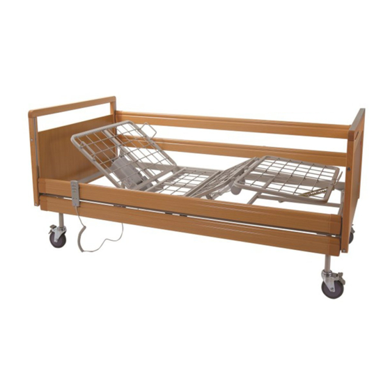
N°2 testiera/pediera N°4 stecche per sponde N°4 slitte per sponde Fig.1 7.2 Kit elettrico per MP370 (letto degenza 3 snodi elettrico mod. GERANIO) Elenco delle parti N°1 centralina elettronica N°1 telecomando N°1 attuatore elettrico alzatesta N°1 attuatore elettrico alzagambe Fig.2... -
Page 6: Kit Elettrico Mp380 (Letto Degenza 3 Snodi Elettrico Elevabile Mod. Gerbera)
7.4 Kit elettrico MP380 (letto degenza 3 snodi elettrico elevabile mod. GERBERA) Elenco delle parti N°1 centralina elettronica N°1 telecomando N°1 attuatore elettrico alzatesta N°1 attuatore elettrico alzagambe N°1 attuatore elettrico elevazione Fig.4 7.5 Struttura letto MP381 Elenco delle parti N°1 telaio rete lato alzatesta N°1 telaio rete lato alzagambe N°1 telaio elevabile con ruote... -
Page 7: Kit Elettrico Per Mp390
7.8 Kit elettrico per MP390 (letto degenza 3 snodi elettrico Trendelemburg mod. GARDENIA) Elenco delle parti N°1 centralina elettronica N°1 telecomando N°1 attuatore elettrico alzatesta N°1 attuatore elettrico alzagambe N°2 attuatori elettrici testiera/ pediera Fig.8 7.9 Struttura letto MP391 (letto degenza 3 snodi Trendelemburg elettrico mod.GARDENIA) Elenco delle parti N°1 telaio rete lato alzatesta N°1 telaio rete lato alzagambe... -
Page 8: Montaggio
8. MONTAGGIO 8.1 MP370 (letto degenza 3 snodi elettrico mod. GERANIO) Fig.12 Fig.11 1. Inserire i due tubolari rettangolari all’interno del telaio lato alzatesta e spingerli fino alla battuta (Fig.11) 2. Unire a questo punto le due parti di rete allineandole e bloccandole con le 4 manopole (Fig.12) 3. - Page 9 5. Inserire la testiera e la pediera in legno (sono due elementi uguali) nei supporti presenti sul telaio facendo attenzione che il perno automatico di bloccaggio si inserisca correttamente all’interno del foro (Fig.15) Fig.15 6. Preparare le sponde per il montaggio nel seguente modo: •...
- Page 10 8. Installare la centralina sull’attuatore con il cavo più corto. Prima di installare la centralina sull’attuatore svolgere le seguenti operazioni: • Collegare alla centralina il cavo di alimentazione; • Inserire sull’attuatore il supporto in plastica come mostrato in Fig.18, con il lato aperto della svasatura rivolto verso il basso; •...
- Page 11 8.2 MP380 e MP381 (letti degenza 3 snodi elettrici elevabili mod. GERBERA) 1. Inserire i due tubolari rettangolari all’interno del telaio lato alzatesta e spingerli fino alla battuta (Fig.24) Fig.24 Fig.25 Immagini a scopo illustrativo 2. Unire a questo punto le due parti di rete allineandole e bloccandole con le 4 manopole (Fig.25) 3.
- Page 12 5. Inserire la testiera e la pediera in legno (sono due elementi uguali) nei supporti presenti sul telaio facendo attenzione che il gancio ruoti e blocchi il perno (Fig.30). Fig.30 6. Preparare le sponde per il montaggio nel seguente modo: •...
- Page 13 8. Installare la centralina sull’attuatore con il cavo più corto. Prima di installare la centralina sull’attuatore svolgere le seguenti operazioni: • Collegare alla centralina il cavo di alimentazione; • Inserire sull’attuatore il supporto in plastica come mostrato in Fig.33, con il lato aperto della svasatura rivolto verso il basso; •...
-
Page 14: Mp390 E Mp391
8.3 MP390 e MP391 (letti degenza 3 snodi elettrici Trendelemburg mod. GARDENIA) 1. Inserire i due tubolari rettangolari all’interno del telaio lato alzatesta e spingerli fino alla battuta (Fig.39) Fig.39 Fig.40 2. Inserire il telaio della testiera e della pediera nei supporti presenti sul telaio della rete facendo attenzione che il perno di bloccaggio si inserisca correttamente all’interno del foro (Fig.41). - Page 15 4. Inserire le due coppie di sponde nella parte inferiore delle guide predisposte sulla testiera e sulla pediera in legno. Eseguire questa operazione prima da un lato e poi dall’altro. Per bloccare l’uscita delle sponde dalle guide, avvitare i fermi nella parte terminale delle guide (Fig.43).
-
Page 16: Montaggio Delle Maniglie Sulle Sezioni (Per Mp370/Mp380/Mp381/Mp390/Mp391)
A questo punto il letto è montato e pronto all’uso. Fig.49 8.4 Montaggio delle maniglie sulle sezioni (per MP370/MP380/MP381/MP390/MP391): 1. Per il montaggio delle maniglie sulle sezioni del letto, utilizzare la maniglia con viti/dadi in dotazione (Fig.50). -
Page 17: Avvertenze Per L'utilizzo
11. MODALITÀ D’USO 11.1 MP370 (letto degenza 3 snodi elettrico mod. GERANIO) Il letto da degenza MP370 (GERANIO) offre la possibilità di regolare l’inclinazione dell’alzatesta e dell’alzagambe attraverso i relativi pulsanti sul telecomando. N.B. PRIMA DI OGNI REGOLAZIONE SI RACCOMANDA DI BLOCCARE LE RUOTE DEL LETTO ATTRAVERSO I FRENI MONTATI SU CIASCUNA RUOTA. -
Page 18: Mp390-Mp391
ATTENZIONE Collegare il cavo di alimentazione per la tensione di rete ad una presa 220-230 VAC A Pulsante regolazione alzatesta (SU) B Pulsante regolazione alzatesta (GIÙ) C Pulsante regolazione alzagambe (SU) D Pulsante regolazione alzagambe (GIÙ) E Pulsante regolazione combinata alzatesta/alzagambe (SU) F Pulsante regolazione combinata alzatesta/alzagambe (GIÙ) G Pulsante regolazione elevazione rete (SU) H Pulsante regolazione elevazione rete (GIÙ) -
Page 19: Manutenzione
12. MANUTENZIONE I dispositivi della linea MOPEDIA by Moretti S.p.A. al momento dell’immissione in commercio sono controllati accuratamente e provvisti di marchio CE. Per la sicurezza del paziente e del medico si raccomanda di far controllare dal produttore o da un laboratorio autorizzato, almeno una volta l’anno, l’idoneità all’uso del prodotto. - Page 20 Tabella 1 Guida e dichiarazione del costruttore-emissioni elettromagnetiche Il dispositivo è previsto per funzionare nell’ ambiente elettromagnetico sotto specificato. Il cliente o l’utilizzatore del dispositivo deve garantire che esso venga usato in tale ambiente. Prove di emissione Conformità Ambiente elettromagnetico-guida Il dispositivo utilizza energia RF solo per il suo funzionamento interno e per la ricarica della batteria.
- Page 21 Tabella 3 Guida e dichiarazione del costruttore-immunità elettromagnetica Il dispositivo è previsto per funzionare nell’ ambiente elettromagnetico sotto specificato. Il cliente o l’utilizzatore del dispositivo dovrebbe assicurarsi che esso venga utilizzato in tale ambiente. Garantire che esso venga usato in tale ambiente. Ambiente elettromagnetico- Prove di immunità...
-
Page 22: Parti Di Ricambio E Accessori
Tabella 4 Distanze di separazione raccomandate tra apparecchi di radiocomunicazione portatili e mobili e NEFTI Il Dispositivo NEFTI è previsto per funzionare in un ambiente elettromagnetico in cui sono sotto controllo i disturbi irradiati RF. Il cliente o l’utilizzatore di NEFTI può contribuire a prevenire interferenze elettromagnetiche assicurando una distanza minima fra gli apparecchi di comunicazione mobili e portatili a RF (trasmettitori) ed il carica batterie di NEFTI durante la fase di carica e l’intero dispositivo NEFTI durante il suo funzionamento come sotto raccomandato, in relazione alla potenza di uscita massima degli apparecchi di radiocomunicazione... -
Page 23: Risoluzione Problemi
17. RISOLUZIONE PROBLEMI SINTOMI PROBABILI CAUSE SOLUZIONE 1. La spina elettrica non è 1. Collegare la spina elettrica collegata alla presa tensione di rete 2. Controllare ed eventualmente collegare il NESSUN COMANDO 2. Il telecomando non è telecomando alla centralina FUNZIONANTE collegato alla centralina 3. -
Page 24: Caratteristiche Tecniche
390) ovvero in legno (MP381-391). Testiera, pediera e per MP370-380-381-390-391 sponde in legno. 18.2 Dimensioni MP370 - letto degenza a tre snodi elettrico (mod. GERANIO) Dimensioni letto: cm 208x102x94h (alla testiera pediera) Dimensioni rete: cm 187x80x42,5h (piano rete da terra) Altezza massima alla testiera/pediera: cm 94 Angolo massimo alzatesta: 70°... - Page 25 MP380 - MP381 Letto degenza a tre snodi elettrico elevabile (mod. GERBERA) Dimensioni letto: cm 208x102x116,5h (alla testiera pediera) Dimensioni rete: cm 187x80x33,5÷65,5h (piano rete da terra) Altezza massima alla testiera/pediera: cm 116,5 Altezza minima alla testiera/pediera: cm 22,5 Altezza minima del telaio da terra: cm 22,5 Angolo massimo alzatesta: 70°...
-
Page 26: Garanzia
19. GARANZIA Tutti i prodotti Moretti sono garantiti da difetti di materiale o fabbricazione per un periodo di 2 (due) anni dalla data di vendita del prodotto, salvo eventuali esclusioni e limitazioni specificate di seguito. Questa garanzia non è valida in caso di uso improprio, abuso o modifica del prodotto e per la mancata aderenza alle istruzioni per l’uso. - Page 27 CERTIFICATO DI GARANZIA Prodotto ____________________________________________________________________ Acquistato in data ___________________________________________________________ Rivenditore _________________________________________________________________ Via _______________________ Località __________________________________________ Venduto a ___________________________________________________________________ Via ________________________ Località _________________________________________ MORETTI S.P.A. Via Bruxelles, 3 - Meleto 52022 Cavriglia (Arezzo) Tel. +39 055 96 21 11 www.morettispa.com email: info@morettispa.com MADE IN P.R.C.
- Page 29 HOSPIYAL BEDS THREE-JOINTED ELECTRIC BEDS INSTRUCTION MANUAL...
- Page 30 7. GENERAL DESCRIPTION ....................PAG.5 7.1 Bed structure MP370 (three-jointed electric hospital bed mod. GERANIO) ....pag. 5 7.2 Electrical kit for MP370 (three-jointed electric hospital bed mod. GERANIO) ..pag. 5 7.3 Bed structure MP380 (three-jointed electric lifting hospital bed mod. GERBERA) ...........pag. 5 7.4 Electrical kit for MP380...
- Page 31 The three-jointed electric hospital beds in the MOPEDIA range by MORETTI S.p.A. have been designed and manufactured to satisfy all your needs for practical and correct use. This user manual contains some suggestions on how to use the wheelchair properly and safely.
- Page 32 Note: Complete product codes, the manufacturer registration code (SRN), the UDI-DI code and any references to used regulations are included in the EU declaration of conformity that Moretti S.p.A. releases and makes available through its channels. 4.1 Reference standards and directives To ensure safety standards for users of the product, Moretti S.P.A tests and repeats the legislation: UNI CEI 60601-2-52.
- Page 33 N°2 headboard/footboard N°4 side slats N°4 side slides Fig. 1 7.2 Electrical kit for MP370 (three-jointed electric hospital bed mod. GERANIO) List of parts N°1 electronic control unit N°1 remote control N°1 head raiser electric actuator N°1 leg raiser electric actuator Fig.
- Page 34 7.4 Electrical kit for MP380 (three-jointed electric lifting hospital bed mod. GERBERA) List of parts N°1 electronic control unit N°1 remote control N°1 head raiser electric actuator N°1 leg raiser electric actuator N°1 lifting electric actuator Fig. 4 7.5 Bed structure MP381 List of parts N°1 mesh frame head raiser part N°1 mesh frame leg raiser part...
- Page 35 7.8 Electrical kit for MP390 (three-jointed electric Trendelenburg hospital bed mod. GARDENIA) List of parts N°1 electronic control unit N°1 remote control N°1 head raiser electric actuator N°1 leg raiser electric actuator N°2 headboard/footboard electric actuators Fig. 8 7.9 Bed structure MP391 (three-jointed electric Trendelenburg hospital bed mod. GARDENIA) List of parts N°1 mesh frame head raiser part N°1 mesh frame leg raiser part...
- Page 36 8. ASSEMBLY 8.1 MP370 (three-jointed electric hospital bed mod. GERANIO) Fig. 12 Fig. 11 1. Insert the two rectangular tubes into the frame at the head raiser end and push them right in (Fig. 11) 2. Join the two parts of the mesh at this point, aligning them and locking them in place with the four knobs (Fig.
- Page 37 5. Insert the wooden headboard and footboard (two identical elements) in the supports on the frame, making sure that the automatic locking pin is correctly inserted into the hole (Fig. 15) Fig. 15 6. Prepare the sides for assembly in the following manner: •...
- Page 38 8. Install the control unit on the actuator with the shortest cable. Perform the following operations before installing the control unit on the actuator: • Connect the power cable to the control unit; • Insert the plastic support onto the actuator, as shown in Fig. 18, with the open side of the tapered part facing downwards;...
- Page 39 8.2 MP380 and MP381 (three-jointed electric lifting hospital bed mod. GERBERA) 1. Insert the two rectangular tubes into the frame at the head raiser end and push them right in (Fig. 24) Fig. 24 Fig. 25 Illustrative images 2. Join the two parts of the mesh at this point, aligning them and locking them in place with the four knobs (Fig.
- Page 40 5. Insert the wooden headboard and footboard (two identical elements) in the supports on the frame, making sure that the clasp rotates and locks the pin in place (Fig. 30). Fig. 30 6. Prepare the sides for assembly in the following manner: •...
- Page 41 8. Install the control unit on the actuator with the shortest cable. Perform the following operations before installing the control unit on the actuator: • Connect the power cable to the control unit; • Insert the plastic support onto the actuator, as shown in Fig. 33, with the open side of the tapered part facing downwards;...
- Page 42 8.3 MP390 and MP391 (three-jointed electric Trendelenburg hospital bed mod. GARDENIA) 1. Insert the two rectangular tubes into the frame at the head raiser end and push them right in (Fig. 39) Fig. 39 Fig. 40 2. Insert the headboard frame and the footboard frame into the supports on the mesh frame, making sure that the locking pin is correctly inserted into the hole (Fig.
- Page 43 4. Insert the two pairs of slats into the lower part of the guides on the wooden headboard and footboard. Perform this operation first on one side and then on the other. Tighten the stops at the end of the guides to prevent the sides from coming out of the guides (Fig.
- Page 44 At this point, the bed is assembled and ready for use. Fig. 49 8.4 Assembly of the handles on the sections (for MP370/MP380/MP381/MP390/MP391) 1. Use the handle with screws/bolts provided for assembly of the handle on the bed sections (Fig. 50).
- Page 45 11. HOW TO USE 11.1 MP370 (three-jointed electric hospital bed mod. GERANIO) The MP370 (GERANIO) hospital bed offers the possibility of adjusting the inclination of the head raiser and the leg raiser, using the relative buttons on the remote control.
- Page 46 WARNING Connect the power cable to a 220-230 VAC mains plug A Head raiser adjustment button (UP) B Head raiser adjustment button (DOWN) C Leg raiser adjustment button (UP) D Leg raiser adjustment button (DOWN) E Combined head raiser/leg raiser adjustment button (UP) F Combined head raiser/leg raiser adjustment button (DOWN) G Mesh lifting adjustment button (UP) H Mesh lifting adjustment button (DOWN)
- Page 47 12. MAINTENANCE MOPEDIA devices manufactured by Moretti S.p.A. are CE marked and carefully checked before being commercialised. For patient and doctor safety, have the product checked at least once a year by the manufacturer or by an authorised laboratory to verify its suitability for use.
- Page 48 Table 1 Manufacturer's guide and declaration - electromagnetic emissions The device is intended to be used in the following electromagnetic conditions. The client or user must ensure that it is used in these conditions. Emission tests Conformity Electromagnetic environment – guide The device uses RF energy only for internal functioning and for charging the battery.
- Page 49 Table 3 Manufacturer's guide and declaration - electromagnetic immunity The device is intended to be used in the following electromagnetic conditions. The client or user must ensure that it is used in these conditions. Make sure it is used in these conditions. Electromagnetic Immunity tests Test level IEC 60601...
- Page 50 Table 4 Recommended separation distances between portable and mobile radio communications equipment and the DEVICE The device is intended to operate in an electromagnetic environment in which RF disturbances are under control. The client or user of the DEVICE can contribute to preventing EM interference by ensuring a minimum distance between the mobile and portable RF communications devices (transmitters) and the DEVICE battery charger during charging and the entire device during its operation as recommended below, in relation to the maximum output power of the radio communication equipment...
- Page 51 17. TROUBLESHOOTING PROBABLE CAUSES SOLUTION PROBLEMS 1. The electric plug is not 1. Connect the electric plug connected to the mains 2. Check and, if necessary, 2. The remote control connect the remote control NO CONTROL is not connected to the to the control unit control unit IS FUNCTIONING...
- Page 52 (MP381-391). Wooden headboard, footboard and sides. 18.2 Dimensions MP370 Three-jointed electric hospital - bed (mod. GERANIO) Bed dimensions: 208x102x94h cm (at the headboard and footboard) Mesh dimensions: 187x80x42.5h cm (mesh base height from the floor) Maximum height at the headboard/footboard: 94 cm Maximum angle of the head raiser: 70°...
- Page 53 MP380 - MP381 Three-jointed electric lifting hospital bed (mod. GERBERA) Bed dimensions: 208x102x116.5h cm (at the headboard and footboard) Mesh dimensions: 187x80x33.5÷65.5h cm (mesh base height from the floor) Maximum height at the headboard/footboard: 116.5 cm Minimum height at the headboard/footboard: 22.5 cm Minimum height of frame from the ground: 22.5 cm Maximum angle of the head raiser: 70°...
- Page 54 19. WARRANTY Moretti products are guaranteed for 2 (two) years from the date of sale against material and manufacturing defects, subject the following limitations. The warranty is voided by improper use, abuse, modifications to the product and failure to follow the instructions. The intended use of the product is given in the user manual Moretti is not liable for damage, injury or any other consequences resulting from installation or use which are not scrupulously conforming with the instructions given in the installation,...
- Page 55 WARRANTY CERTIFICATE Product _______________________________________________________________________ Purchased on (date) ____________________________________________________________ Retailer ______________________________________________________________________ Address _______________________ Town/city ______________________________________ Sold to ________________________________________________________________________ Address _______________________ Town/city ______________________________________ MORETTI S.P.A. Via Bruxelles, 3 - Meleto 52022 Cavriglia (Arezzo) Tel. +39 055 96 21 11 www.morettispa.com email: info@morettispa.com MADE IN P.R.C.
- Page 57 CAMAS PARA INTERNACIÓN 3 ARTICULACIONES ELÉCTRICA MANUAL DE INSTRUCCIONES...
- Page 58 (cama para internación 3 articulaciones Trendelenburg eléctrica mod.GARDENIA) .pag. 8 8. MONTAJE ......................... PAG.8 8.1 MP370 (cama para internación 3 articulaciones eléctrica mod. GERANIO) ..pag. 8 8.2 MP380 y MP381 (camas de 3 articulaciones eléctricas elevables mod. GERBERA) ....pag. 11 8.3 MP390 y MP391...
-
Page 59: Códigos
3. FINALIDAD Las camas MOPEDIA sirven para las personas internadas por motivos de salud en hospitales, en centros de asistencia sanitaria o en el domicilio del paciente. -
Page 60: Normas Y Directivas De Referencia
Nota: Los códigos completos de los productos, el código de registración del Fabricante (SRN), el código UDI-DI de base y eventuales referencias a normas utilizadas se encuentran en la Declaración de Conformidad UE que MORETTI SPA emite y mete a disposición a través de sus canales. -
Page 61: Descripción General
2 cabeceros/pieceros 4 varillas para borde 4 correderas para borde Fig.1 7.2 Kit eléctrico para MP370 (cama para internación 3 articulaciones eléctrica mod. GERANIO) Lista de las partes 1 centralita electrónica 1 mando a distancia 1 actuador eléctrico levanta-cabeza 1 actuador eléctrico levanta-piernas... -
Page 62: Estructura Cama Mp380
7.3 Estructura cama MP380 (cama para internación 3 articulaciones eléctrica elevable mod. GERBERA) Lista de las partes 1 bastidor somier lado levanta-cabeza 1 bastidor somier lado levanta-piernas 1 bastidor elevable con ruedas 2 cabeceros/pieceros 4 varillas para borde 4 correderas para borde Fig.3 7.4 Kit eléctrico MP380 (cama para internación 3 articulaciones eléctrica elevable mod. -
Page 63: Estructura Cama Mp390
7.7 Estructura cama MP390 (cama para internación 3 articulaciones eléctrica Trendelenburg mod. GARDENIA) Lista de las partes 1 bastidor somier lado levanta-cabeza 1 bastidor somier lado levanta-piernas 2 tubos rectangulares conexión bastidor 4 pomos para bloquear el bastidor 1 cabecero 1 piecero 4 varillas de madera para borde 4 correderas plásticas para borde... -
Page 64: Kit Eléctrico Para Mp391
1 actuador eléctrico levanta-piernas 2 actuadores eléctricos cabecero/ piecero Fig.10 8. MONTAJE 8.1 MP370 (cama para internación 3 articulaciones eléctrica mod. GERANIO) Fig.12 Fig.11 1. Poner los dos tubos rectangulares dentro del bastidor del lado levanta-cabeza y empujarlos hasta el tope (Fig.11) 2. - Page 65 Fig.14 Fig.13 4. Atornillar las ruedas a los soportes (para ello se recomienda bloquear el freno sobre cada rueda para poder atornillar fácilmente a mano). Apretar enérgicamente (Fig.14) 5. Poner el cabecero y el piecero de madera (son dos elementos iguales) en los soportes que se encuentran en el bastidor, prestando atención para que el perno automático de bloqueo se introduzca correctamente en el...
- Page 66 7. Poner los dos pares de bordes en la parte inferior de las guías predispuestas en el cabecero y en el piecero de madera. Realizar esta operación primero de un lado y después del otro, pulsando la tecla de bloqueo para la encastrar la corredera en la guía;...
- Page 67 - conectar el cable del actuador del lado del levanta-pies al canal “foot”; A - No conectado B - No conectado C - Actuador eléctrico levanta-piernas D - Actuador eléctrico levanta-cabeza E - Mando a distancia • Disponer cables alojamientos sujetacables presentes en la centralita y volver a colocar la tapa de plástico Ahora la cama está...
- Page 68 • Ensamblar los bastidores haciendo desplazar los coji- netes dentro de las guías del bastidor del somier (Fig.28); • Desplazar el bastidor del somier hasta que los pernos del bastidor elevable queden bloqueados por el gancho situado sobre el bastidor del somier (Fig.29).
- Page 69 7. Poner los dos pares de bordes en la parte inferior de las guías predispuestas en el cabecero y en el piecero de madera. Realizar esta operación primero de un lado y después del otro, pulsando la tecla de bloqueo para la encastrar la corredera en la guía;...
- Page 70 A - No conectado B - Actuador eléctrico de elevación del somier C - Actuador eléctrico levanta-piernas D - Actuador eléctrico levanta-cabeza E - Mando a distancia • Disponer cables alojamientos sujetacables presentes en la centralita y volver a colocar la tapa de plástico Ahora la cama está...
- Page 71 • Colocar los patines de plástico como elemento de conexión de los bordes de un lado y del otro, prestando atención para que la parte triangular en punta quede hacia el lado redondeado del borde (Fig.42) • Realizar la misma operación con las otras dos varillas para formar el par de bordes Fig.42 4.
-
Page 72: Montaje De Los Asideros Sobre Las Secciones (Mp370/Mp380/Mp381/Mp390/Mp391)
Ahora la cama está montada y lista para usar. Fig.49 8.4 Montaje de los asideros sobre las secciones (MP370/MP380/MP381/MP390/MP391): 1. Para el montaje de los asideros sobre las secciones de la cama, utilizar el asidero con tornillos / tuercas en dotación (Fig.50). -
Page 73: Antes De Cada Uso
11. MODO DE USO 11.1 MP370 (cama para internación 3 articulaciones eléctrica mod. GERANIO) La cama para internación MP370 (GERANIO) ofrece la posibilidad de regular la inclinación del levanta-cabeza y del levanta-piernas mediante las teclas del mando a distancia. Nota ANTES DE CUALQUIER REGULACIÓN SE RECOMIENDA BLOQUEAR LAS RUEDAS DE LA CAMA CON LOS FRENOS DE CADA RUEDA. - Page 74 ATENCIÓN Conectar el cable de alimentación a una toma eléctrica de 220-230 VCA A Tecla de regulación del levanta-cabeza (ARRIBA) B Tecla de regulación del levanta-cabeza (ABAJO) C Tecla de regulación del levanta-piernas (ARRIBA) D Tecla de regulación del levanta-piernas (ABAJO) E Tecla de regulación combinada levanta-cabeza / levanta-piernas (ARRIBA) F Tecla de regulación combinada levanta-cabeza / levanta-piernas (ABAJO) G Tecla de regulación de la elevación del somier (ARRIBA)
-
Page 75: Mantenimiento
12. MANTENIMIENTO Los productos de la línea MOPEDIA fabricados por Moretti S.p.A. que se introducen en el comercio han sido cuidadosamente controlados y provistos de marca CE. Para la seguridad del paciente y del médico se recomienda hacer controlar la idoneidad del producto al fabricante o a un laboratorio autorizado al menos una vez al año. - Page 76 Tabla 1 Guía y declaración del fabricante - emisiones electromagnéticas El producto está diseñado para funcionar en el ambiente electromagnético especificado a continuación. El cliente o el usuario del producto debe garantizar el uso en dicho ambiente. Pruebas de emisión Conformidad Ambiente electromagnético-guía El producto utiliza energía RF sólo para el...
- Page 77 Tabla 3 Guía y declaración del fabricante - inmunidad electromagnética El producto está diseñado para funcionar en el ambiente electromagnético especificado a continuación. El cliente o el usuario del producto debe asegurarse de que el uso se efectúe en dicho ambiente. Garantizar el uso en este tipo de ambiente. Nivel de prueba Pruebas de inmunidad Nivel de conformidad...
-
Page 78: Repuestos Y Accesorios
Tabla 4 Distancias de separación recomendadas entre los equipos de comunicación portátiles y móviles y el producto. El producto está diseñado para funcionar en un ambiente electromagnético donde las interferencias RF estén bajo control. El cliente o el usuario del producto puede contribuir a evitar interferencias electromagnéticas manteniendo una distancia mínima entre los aparatos de comunicación por radiofrecuencia portátiles y móviles (transmisores) respecto del cargador de baterías del producto durante la carga y respecto del producto según se indica a continuación, en base a la potencia de salida máxima de los aparatos de radiocomunicación. -
Page 79: Resolución De Problemas
17. RESOLUCIÓN DE PROBLEMAS POSIBLE CAUSA SOLUCIÓN PROBLEMA 1. La clavija eléctrica no 1. Conectar la clavija eléctrica está conectada a la toma de tensión de red 2. Controlar y eventualmente conectar el mando NO FUNCIONA 2. El mando a distancia no a distancia a la centralita está... -
Page 80: Características Técnicas
(MP381-391). Cabecero, piecero y bordes de madera. 18.2 Medidas MP370 - cama para internación de tres articulaciones eléctrica (mod. GERANIO) Medidas de la cama: 208x102x94h cm (al cabecero piecero) Medidas del somier: cm 187x80x42,5h (somier de suelo) Altura máxima al cabecero/piecero: cm 94 Ángulo máximo levanta-cabeza: 70°... - Page 81 MP380 - MP381 Cama para internación de tres articulaciones eléctrica elevable (mod. GERBERA) Medidas de la cama: 208x102x116,5h cm (al cabecero piecero) Medidas del somier: 187x80x33,5÷65,5h cm (somier de suelo) Altura máxima al cabecero/piecero: cm 116,5 Altura mínima al cabecero/piecero: 22,5 cm Altura mínima del bastidor al suelo: 22,5 cm Ángulo máximo levanta-cabeza: 70°...
-
Page 82: Garantía
19. GARANTÍA Todos los productos MORETTI tienen una garantía de 2 años desde la fecha de venta por defectos de fabricación o de material, sin perjuicio de eventuales exclusiones y de las limitaciones especificadas a continuación. La garantía no se aplica en caso de daños causados por uso inadecuado, abusos, alteraciones y en caso de que no se respecten las instrucciones de uso. - Page 83 CERTIFICADO DE GARANTÍA Producto _____________________________________________________________________ Fecha de compra ______________________________________________________________ Distribuidor __________________________________________________________________ Calle _______________________ Localidad ________________________________________ Vendido a ____________________________________________________________________ Calle __________________________ Localidad _____________________________________ MORETTI S.P.A. Via Bruxelles, 3 - Meleto 52022 Cavriglia (Arezzo) Tel. +39 055 96 21 11 www.morettispa.com email: info@morettispa.com MADE IN P.R.C.
- Page 84 ORETTI Via Bruxelles, 3 - Meleto Tel. +39 055 96 21 11 www.morettispa.com 52022 Cavriglia (Arezzo) Fax. +39 055 96 21 200 info@morettispa.com...
Need help?
Do you have a question about the MP370 and is the answer not in the manual?
Questions and answers