Table of Contents
Advertisement
Quick Links
Advertisement
Table of Contents

Subscribe to Our Youtube Channel
Related Manuals for LMI Technologies FocalSpec


Summary of Contents for LMI Technologies FocalSpec
- Page 1 FocalSpec 3D Line Confocal Scanner UULA...
- Page 2 LMI Technologies, Inc. Trademarks and Restrictions FocalSpec™ is a registered trademark of LMI Technologies, Inc. Any other company or product names mentioned herein may be trademarks of their respective owners. Information contained within this manual is subject to change.
-
Page 3: Table Of Contents
1.5 Unpacking and Assembling UULA ......................... 9 1.5 Installing UULA Software..........................16 1.5.1 Manual Network Interface Configuration ..................18 1.6 Installing Focalspec Map ..........................18 1.7 Installing Mountains Map v8 ......................... 19 1.8 UULA with sensors LCI1220 and LCI1620 ....................20 1.8.1 UULA LCI1220/1620 sensor set up cables .................. - Page 4 2.11.1 Analyses ............................ 66 2.10.2 Startup and Help ........................78 2.10.3 FocalSpec Map Versions ......................78 2.11 Declaration of Conformity ........................... 82 3 Maintenance and Service ..................83 3.1 Continuous Maintenance ..........................83 3.2 Monthly Maintenance ............................ 83 3.3 Cleaning the Calibration Mirror ........................84 4 What Is New in the Latest SW Version ...............
-
Page 5: Uula Installation Manual
1 UULA Installation Manual This chapter contains the UULA Installation Manual. The UULA User Manual is integrated into the software and can be opened by selecting Help from the header. 1.1 Safety Instructions Please read the manual carefully and observe the safety instructions before you begin working with the system. If you are unsure or have any questions, please contact the supplier. -
Page 6: Measurement Table
Table 3: Cautions Warning sign Warning Do not unplug the sensor cable connectors when the power is on. Handle the calibration mirror with care. Do not touch the calibration mirror surface (see Cleaning the Calibration Mirror on page 78). Warning sign Warning This equipment is not intended for use in residential environments and may not provide adequate protection to radio reception in such environments. -
Page 7: Delivery Package Contents
An envelope containing UULA software on a USB memory stick and FocalSpec Map USB dongle. The installation code needed for FocalSpec Map installation will be delivered separately by LMI technical support. The sensor will be delivered in a separate package. -
Page 8: Computer And Ethernet
Figure 2 Delivery Package Contents 1.4 Computer and Ethernet Note: If you use LCI1220 or LCI1620, see 1.8 UULA with sensors LCI1220 and LCI1620 If the delivery does not include a computer, the items below are required: • A computer. The minimum requirements are: •... -
Page 9: Unpacking And Assembling Uula
1.5 Unpacking and Assembling UULA This section describes how to unpack and assemble the UULA hardware. Before you start, make sure that you have: • A PH2 screwdriver or a cordless drill. • A pump lift. • A 2 mm Allen key. •... - Page 10 7. Remove the corrosion protection paper. 8. Remove the envelope containing a USB memory stick with UULA software installer and a FocalSpec Map USB dongle. 9. Remove the fastening strips, which run through the screw pin anchor shackles and secure the device to the pallet.
- Page 11 Warning: Danger of crushing! The UULA scanner weighs approximately 120 kg / 265 lbs. A pump lift is required to handle the scanner. 12. Remove the fastening strips around the sensor, and the fastening pins from the measurement table. 13. Remove the lifting eyebolts by unscrewing them. Figure 6 Removing the Lifting Eyebolts Note: It is extremely important that you remove the lifting eyebolts, as they will collide with the Z-axis...
- Page 12 Z-axis locking screw Z-axis adjustment knob Brake mechanism adjustment screw (Allen screw) Figure 7 Fastening the Z-axis Adjustment Knob (with Z-axis locking screw) 15. Open the sensor mounting finger by unscrewing thumbscrew until the sensor head locking pin is no longer visible. 16.
- Page 13 Figure 8 The Controller 17. Remove the sensor from its package. Warning: Danger of crushing! The sensor weighs approximately 30 kg / 66 lbs. Two persons are required to handle the sensor. Before you continue, ensure that the lens cover is in place: Figure 9 Lens Cover...
- Page 14 18. Lower the sensor into its place in a slightly tilted position. Before you start, check that the Z-axis has been raised enough, so that the sensor fastening plate is level with the device chassis, and that the Z-axle locking handle is locked (applies to the non-motorized version, U_XY). Z-axis adjustment knob Figure 10 Lifting the Sensor in Place —...
- Page 15 20. Lock the sensor in place by using the thumbscrew at the lower part of the Z-axis mechanism. Use approximately 1 Nm torque. Figure 12 Locking the Sensor in Place Note: If you are installing a motorized Z version (U_XYZ), make sure that the Z-axis locking handle is left loose.
-
Page 16: Installing Uula Software
25. Check that the main switch is in the Off (“0”) position. Figure 13 Power Main Switch at the Back of the UULA Frame 26. Connect the power cable to a grounded outlet. 27. Connect the Ethernet cable between the scanner and computer. Note: UULA requires its own dedicated Ethernet port. - Page 17 38. Allow installer to create a desktop shortcut and select Next > 39. Select Install 40. Install CloudCompare (only if not yet installed). 41. In the FocalSpec VEVO Filter Driver setup window: a) Select Install. b) Select Yes to the network adapter parameters question.
-
Page 18: Manual Network Interface Configuration
1. Copy setup.exe from the USB memory stick or download it from LMI support site to the C drive. 2. If you have purchased FocalSpec Map and have a license dongle, insert it into the USB drive prior to installing. -
Page 19: Installing Mountains Map V8
This section describes how to install the Mountains Map software. Proceed as follows: 1. Before installing a new version of the software: • Uninstall all previous versions, also Focalspec Map software (in Add or Remove programs) • Make sure you have Administrator rights •... -
Page 20: Uula With Sensors Lci1220 And Lci1620
1.8 UULA with sensors LCI1220 and LCI1620 There are two options to connect LCI1220/1620 sensor to UULA: • 10 Gbit optical Ethernet directly to desktop PC having additional network adapter with SFP+ interface. This is recommended option • Switch with SFP+ between UULA and desktop PC or laptop without SFP+ interface. This option has limited maximum scanning frequency. -
Page 21: Uula Lci1220/1620 Using Through Switch
1.8.3 UULA LCI1220/1620 using through switch If LCI1220/1620 sensor want to be used in UULA with PC or laptop without SFP+ connection, a switch is needed. With switch the maximum scanning frequency for continuous measuring is about 8000 Hz measuring one surface. With multiple surfaces the frequency is respectively lower. -
Page 22: Uula User Manual
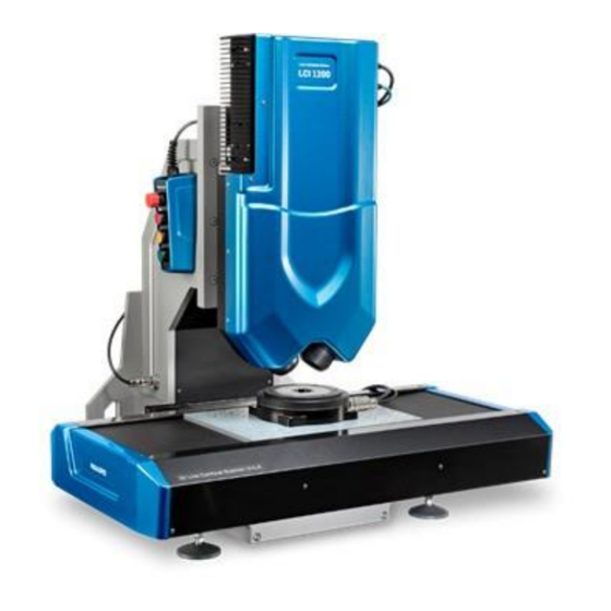
The UULA User Manual is integrated into the software and can be opened by selecting Help from the header. FocalSpec 3D Line Confocal Scanner UULA is an optical 3D imaging and metrology system for accurate sub-micron measurements on any material. It provides: •... -
Page 23: Computer And Ethernet
Figure 20 UULA Measurement System 2.1.2 Computer and Ethernet Note: If you use LCI1220 or LCI1620, see 1.8 UULA with sensors LCI1220 and LCI1620 If the delivery does not include a computer, the items below are required: • A computer. The minimum requirements are: •... -
Page 24: Logging In
The Manage Users button is visible when the software is used for the first time. Always create a new administrator user account at this time. The default fsadmin account is only for possible remote support from FocalSpec. Proceed, as follows: Start UULA. - Page 25 Figure 18. Login Select Manage Users. The screen below is opened: Figure 19. User Management Select Add. The screen below is opened: Figure 20. User window...
- Page 26 Enter information, as follows: • Username – Enter the username of the new user. • Password – Enter the password of the new user. • Access level – Enter the access right level of the new user. Select OK. Removing users Proceed, as follows: Start UULA.
- Page 27 Defining anonymous access An administrator can allow users to login anonymously, without writing a username and password. Proceed, as follows: Start UULA. The screen below is opened: Figure 23. Login Select Manage Users. The screen below is opened: Figure 24. User Management From the Allow anonymous login on level drop-down menu, select the anonymous access level, which you want to use..
-
Page 28: Main Window
2.2.4 Main Window UULA main window consists of header and footer and four main tabs: • Measurement (See chapter Measurement) • Analysis (See chapter Analysis) • Recipes (See chapter Recipes) • Calibration (See chapter Calibration) The header area is depicted in the figure below: Figure 25 Header The settings on the header are: •... -
Page 29: Measurement
Figure 30 Settings Window The options are: • Units • Metric — Use the metric system units. • Imperial — Use the imperial system units. • Measurement • Overwrite measurements automatically — If this option is selected, the measurement on the same name will be overwritten with a warning. -
Page 30: Analysis
• Job — The job selected for the selected recipe. • Width — The measurement width. • Length — The measurement length. • X resolution — The X resolution length. • Y resolution — The Y resolution length. • LED Pulse — LED pulse width. •... -
Page 31: Recipes
Viewing scanning results. 2.2.7 Recipes On the Recipes tab, you can define recipe-related parameters. The Recipes tab is depicted in the figure below: Figure 29 Recipes Tab The settings on the Recipes tab are: • Recipe settings — Settings related to the selected scanning recipe. •... - Page 32 Figure 30 Measurement Table Coordinates • Width — Defines the scan width, that is, how many sweeps will be used. One sweep width is the same as the sensor profile length, which is equal to the scan line interval above. •...
- Page 33 • Material Type — Simplified peak detection configuration based on material type. Available material types are Opaque, Mirror and Transparent. If user selects Custom type, customizable Peak Detection values become available. Figure 31 Customizable peak detection parameters • Detection filter — Detection filter value defines the length (in number of pixels) used to calculate the average intensity.
- Page 34 • Blue area: second and later scanning jobs, based on the Scanning Jobs values. Note: If the Job is below the Master, the blue area is not visible. • Advanced Camera Parameters — Advanced settings related to the camera. The Advanced Camera Parameters screen is depicted in the figure below: Figure 33 Advanced Camera Parameters The Advanced Camera Parameters are:...
- Page 35 • Surface Mode — Sorts peaks and filters top, bottom or brightest profile. This is preprocessing done in the sensor which can be used to reduce the amount of points in the Ethernet. • Layer Sorting Order — Layer sorting from top to bottom, from bottom to top or from max intensity to lower and top to bottom.
- Page 36 • Bitmap Viewer • Start the next measurement by using none recipe — Select Change Recipe to select a different recipe for the next scan. See also chapter Multiple Scans with Different Rotation Angle • After measurement unload sample to — Select Select position to automatically return the table to the position selected with the Load / Unload function in the Motor moving area after the measurement has been completed.
- Page 37 • Move the table to the right. If you enable the Show selection if footer slider, an arrow icon appears in the bottom bar, with which you can move the table to the selected position and back to the measurement start position. •...
- Page 38 Figure 38. Camera Preview Signal The settings on the Recipes tab in the camera preview mode are: • Intensity — Displays intensity graph. • Surface — All or Layers. If Layers is selected multiple layers are displayed based on Surface Mode selection in Advanced Camera Parameters •...
-
Page 39: Calibration
Raw image selection displays actual raw image data from the sensor. The image can be zoomed with the mouse wheel to view more details. When the cursor is over the image, the intensity diagram is displayed on the chart below the image. - Page 40 Caution: Do not touch the calibration mirror surface. The three calibration samples (number 1 in the figure below) must be on the right-hand side of the calibration mirror when looking from the front. Figure 41 Calibration Mirror If you have LCI1600 or LCI1620, add a paper (such as a Post-it Note) to hide the left side of the groove specimen, as seen in the picture below: Figure 42.
- Page 41 The Set Groove Position window opens, and the table moves so that the small groove is below the sensor. Figure 43 Set Groove Position Use the Auto Z or Z arrows to adjust the sensor height to get the groove specimen visible. The software remembers previously used X and Y positions, and the following two steps are typically only needed when the sensor is changed: •...
- Page 42 Select Move to Small Mirror. The table moves to the round flatness calibration mirror. 6. Adjust the sensor angle. Adjust the sensor angle to horizontally level the profile. Turn on Auto Zoom above the profile window. You can adjust the sensor angle by opening the lock screw (B) and turning the tilt angle screw (A) clockwise or counterclockwise.
- Page 43 Figure 46. Z-Calibration statistics Z-linearity is the maximum Z-calibration error within the Z-range. Flatness is the maximum Z-error compared to the flat surface over the measurement area. Z-repeatability is the standard deviation of Z measurements averaged over the measurement area. After the Z-Calibration, the software asks whether the scaling check should be run or not.
- Page 44 Figure 47. Calibration verification statistics Figure 48 Verification result Calibration View visually shows the result of the verification measurement with the groove map. The groove map is a 3D model, and you can view the details by zooming and turning it with the mouse. By placing the mouse cursor over the map, you can see the Groove Height profile from the specified Z-location, in a chart below the map.
- Page 45 Check Scaling, Verify and System Calibration in succession. Again, select Accept and Save to finish the calibration. 13. Optional: Select Intensity Calibration. The Set Sensor Height window opens Use the Auto Z or Z arrows to adjust the sensor height. Average level must be between the green lines at the top of the sensor’s Z-range.
- Page 46 Figure 50. The calibration block for X-Direction scans Use Adjust Position X and Y arrows to move the sensor to the center of Z-Compensation calibration block. Use the Auto Z or Z-height arrows to adjust the sensor height. Figure 57. Z-compensation target surface is on 0-level Make sure that the calibration block rotation is correct.
- Page 47 Figure 58. Scanning is on-going in X-direction You can wait until the whole z-range is measured, or stop the calibration if smaller z-range is enough. When the scanning is competed turn the sample 90 degrees to Y-direction position like in the picture below.
-
Page 48: Scanning
Figure 60. Scanning preview in Y-direction If lines are not horizontal correct the rotation of the calibration block press ‘Stop’ and ‘Start Y- Direction’. Finally press ‘Save’-button to accept calibration. When calibration is saved the Z-Compensation calculation can be enabled to the recipe in advanced parameters section. 2.4 Scanning This section describes how to make the first scan of a new sample. - Page 49 For LCI1200: • Mirror — 2-4 µs • Glass — <10 • Paper — ~100 • PCB — ~600 (dark green solder mask) For LCI1201 and LCI1600, led pulse widths are close to the LCI1200 values. For LCI401, led pulse widths are typically three times higher than the LCI1200 values. 6.
- Page 50 See 2.2.7 Recipes for usage of parameter 21. Select the output file formats. The output file formats are: • FocalSpec Map — Use the .sur file format. • PCD — Use the .pcd file format. • Bitmap — Use the .bmp intensity file format.
-
Page 51: Viewing Scanning Results
.sur files are opened in the FocalSpec Map component (see chapter FocalSpec Map User Manual). For help in the FocalSpec Map, click an empty space on the tab and press the F1 button. Proceed, as follows: Select the Analysis tab. -
Page 52: Measurement Table
• Color scheme • Distance measurement — Lets you select two points to measure the distance between them. • Coloring mode — Applies colors to points to represent height , intensity or height coloring with intensity.. Height coloring can be customized in a color scheme editor. Custom color scheme is stored to the settings file. -
Page 53: Controller
• P1 — Press the green button to start scanning. The light indications are: • Blinking — The table movement is controlled by the FocalSpec software from the PC. • On — The table is on the manual control mode. -
Page 54: Parameter Guide
2.7 Parameter Guide 2.7.1 3D and Intensity Profiles Figure 54. 3D and intensity profiles 2.7.2 LED Pulse Width Increasing the LED Pulse Width will increase the optical signal so that weaker reflecting surface areas can also be seen. 2.7.3 Peak Threshold The LCI sensor detects the surface and provides a Z height reading and an Intensity reading when the Intensity value measured exceeds the Peak Threshold value. -
Page 55: Getting Optimum Performance From The Lci Sensor
Figure 55 Effect of FIR Length 2.7.6 Getting Optimum Performance from the LCI Sensor This section describes how to get optimum performance from the LCI sensor. Proceed as follows: 1. Position the sample so that the areas requiring the best accuracy are in the middle section of the frame (middle Z-level). -
Page 56: Z-Compensation
2.7.7 Z-Compensation Z-Compensation calculation can enabled/disabled if Z-Compensation calibration is done. Following parameters can be used to fine-tune the compensation: X Bright To Dark Mul: Z-Compensation multiplication factor for X-edges from bright to dark. Direction is from left to right. 0 = no compensation, 1.0 default. -
Page 57: Multiple Scans With Different Rotation Angle
The jobs are combined if the output file format allows it: • The PCD and CSV file formats combine all jobs. • The SUR file format combines all jobs, if the dimensions are equal or if the jobs are within the master job and use the same Y resolution. - Page 58 Figure 58 Output Settings 1 Figure 590. Output Settings 2...
-
Page 59: Troubleshooting
Scan result not There is no .sur result Do not use the Calibration recipe for The selected recipe is saved in FocalSpec file. measuring, select another recipe. Calibration. Map .sur format. There are no... - Page 60 There is long gap It is possible that The scanner does not Decrease the length of the scan. Separate in scanning, during the data will not be see the object. short scans to two different recipes. which the scanner saved. does not see the object.
-
Page 61: Cloudcompare User Manual
2.10 CloudCompare User Manual CloudCompare is a 3D point cloud (and triangular mesh) processing software package. It was originally designed to perform comparisons between two dense 3D points clouds, such as the ones acquired with a laser scanner, or between a point cloud and a triangular mesh. -
Page 62: Using Cloudcompare
2.10.2 Using CloudCompare This chapter contains examples on how you can use CloudCompare to view measurement data. Opening a File You can open a *.pcd file by selecting File > Open. Figure 60 Opening a File Select the object in DB Tree window. Figure 61. - Page 63 Figure 62 Editing Colors and the Height Ramp - 1 Figure 63 Editing Colors and the Height Ramp - 2 Banding In Banding, you can set the banding period in micrometers. The color scale covers each defined banding period. Figure 64 Banding - 1...
- Page 64 Figure 65 Banding - 2 Figure 66 Banding Period 300 µm Zooming You can zoom in to view more details.
- Page 65 Figure 80. Zooming Saving a File You can save the screen view as a BMP picture by selecting Display > Render to file. Figure 81. Saving a File...
-
Page 66: Focalspec Map User Manual
2.11 FocalSpec Map User Manual FocalSpec Map is a comprehensive analyzing platform, which has an extensive help section assisting in software use. Using FocalSpec Map is introduced to customers during the initial machine installation, which gives new UULA users the confidence to explore the software. - Page 67 Figure 68 Rotating a Picture Figure 69 Rotated Picture To open the 3D view, select Studies > View group > 3D View.
- Page 68 Figure 70 3D View To level the measured result, select Operators > Adjust position group > Level. Figure 71 Levelling a Surface...
- Page 69 Figure 72 Levelled Surface To measure dimensions, select Studies > Geometry group > Distance measurement. Figure 73 Measuring Dimensions To study the profile, select Operators > Extract group > Extract profile.
- Page 70 Figure 90. Studying the Profile Note: In the top right-hand corner you can select Average and the number of points. When, for example, defining surface roughness Ra, this may give a more reliable figure. Figure 91. Extracted Profile To study the surface in more detail, select Operators > Extract group > Extract area.
- Page 71 Figure 92. Studying the Surface Figure 74 Extracted Area To get a set of numeric roughness parameters, select Studies > Parameters group > Parameter table.
- Page 72 Figure 75 Parameter Table 2.10.1.2 Sample 2 – 2 € Coin Open the *.sur file by selecting Studiables > Load a studiable. Figure 76 Opening a File To rotate the picture, select Operators > Adjust position group > Rotate.
- Page 73 Figure 77 Rotating a Picture Figure 78 Rotated Picture To open the 3D view, select Studies > View group > 3D View.
- Page 74 Figure 79 3D View To level the measured result, select Operators > Adjust position group > Level. Figure 80 Levelling a Picture To measure dimensions, select Studies > Geometry group > Distance measurement. Figure 100. Measuring Dimensions To study the profile, select Operators > Extract group > Extract profile.
- Page 75 Figure 101. Studying the Profile Figure 102. Extracted Profile To study the surface in more detail, select Operators > Extract group > Extract area. Figure 81 Extracted Area...
- Page 76 Figure 82 Studying the Surface To filter the roughness to study the sample form, select Operators > Filter group > Standard filter. Figure 83 Filtering the Picture...
- Page 77 Figure 84 Filtered Picture To set the step height, select Studies > Step height. Figure 85 Setting the Step Height Figure 86 Step Height...
-
Page 78: Startup And Help
A reference guide has extensive contents, including well visualized instructions. The search function is handy to find more information on the subject. Figure 88 Help 2.10.3 FocalSpec Map Versions There are three different FocalSpec Map versions, described in the sections below. FocalSpec Map Standard... - Page 79 • Grains & Particles 2.10.3.1 FocalSpec Map Extended Version This section describes the modules in the FocalSpec Map extended version. 2D Advanced Surface Texture Figure 89. 2D Advanced Surface Texture Everything that you need for advanced 2D surface texture analysis •...
- Page 80 frequency spectrum and power spectrum density plots - carry out autocorrelation and intercorrelation studies. • Fractal analysis - analyze the fractal dimension of a profile using the enclosing boxes and morphological envelope methods. • Overcome measurement limits virtually - join overlapping profiles to overcome physical measurement limits virtually, with automatic calculation of the overlap zone.
- Page 81 • Dynamic and static populations - declare whether a population is static (all measurements are done) or dynamic (measurements are ongoing) - new measurements in a dynamic population are analyzed automatically and statistics are refreshed to take new data into account. •...
-
Page 82: Declaration Of Conformity
2.11 Declaration of Conformity Figure 92 Declaration of Conformity... -
Page 83: Maintenance And Service
3 Maintenance and Service If there are any questions on maintenance and service, please contact LMI by submitting a technical support request through https://support.lmi3d.com (recommended) or by email at support@lmi3d.com. The system is nearly maintenance-free and does not need daily or weekly maintenance other than keeping the system clean. -
Page 84: Cleaning The Calibration Mirror
3.3 Cleaning the Calibration Mirror This section describes how to clean the calibration mirror. Occasionally, the calibration mirror may require cleaning. If this is the case, use compressed air to blow away any dust or debris on the calibration mirror. The compressed air must be clean and oil-free; otherwise oil may end up on the calibration mirror. -
Page 85: What Is New In The Latest Sw Version
Uula support for sensor LCI1220 and LCI1620 FocalSpec Map not included in installer. • Focalspec Map / Mountains Map software is recommended analysis tools for Uula scanner. Uula 2.2.0 installation package does not include before mentioned programs, but those need to be installed separately. - Page 86 • Median Intensity • Fill Gap Max • Trim Edges • Noise Removal X and Y • Clustering Distance X and Z • Minimum Length for Cluster • Missing First Layer Distance • Missing First Layer X Distance • Missing First Layer Min Length •...
-
Page 87: Technical Specifications
Technical Specifications You can check the software and firmware versions from the About dialog in the UULA software header. The technical specifications for the FocalSpec 3D Line Confocal Scanner UULA are presented in the table below: Table 4: Technical Specifications... - Page 88 Language FocalSpec Map analysis software 3D data output 3D point cloud data 3D data format .sur, .pcd, .bmp, .csv 2D data output 2D intensity data 2D data format .bmp Reporting PDF, RTF, Excel compatibility Language versions EN, FR, DE, ES, IT, PL, JP, CN, KR, BR...
- Page 89 0.13 μm Z repeatability Stand-off distance 20.58 mm Depth of field 3.00 mm LCI1600 sensor Sensor High Precision Line Confocal Sensor Measurement method Optical Scanning method Line Number of points/line 2048 Optical profile length 16.6 mm Pixel size X 8.1 µm Pixel size Y 36.0 µm 0.24 μm...
- Page 90 Operational conditions Ambient temperature 22 °C ± 2 °C (68–75 °F) Humidity 30–50 % Environment Minimum: Class ISO 9 (ISO 14644-1) / Room air (FED STD 209E)
-
Page 91: Legal And Safety Information
Please read this document carefully. Before installing this Product, you need to accept the terms of this End-User License Agreement (EULA). By installing or using the FocalSpec XY Scanner UULA software you agree that you have read all of the terms of this EULA and that you fully accept to be bound by these terms. - Page 92 Distributor. Installation Product installation requires valid FocalSpec sensor license key. User may install the Product on any number of computers. The Product can be run with the sensor(s) which the license key(s) has been registered into. The User is responsible that correct sensor specific license keys and calibration files are installed.
- Page 93 Bugs can be reported to LMI by submitting a technical support request through https://support.lmi3d.com (recommended) or by email at support@lmi3d.com. Bug reports shall include detailed explanation on how to reproduce the bug. Additional files (data files, documents) can be sent to help reproducing the bug. The Editor does its best efforts to ensure the quality of the product.
-
Page 94: Disclaimer
Technologies Inc. All rights are reserved. Copying, including reproducing, storing, adapting or translating, any or all of this material requires the prior written consent of LMI Technologies Inc. The information on this document is subject to change and may be amended or deleted without prior notice. We expressly reserve the right to change the products without prior notice.
Need help?
Do you have a question about the FocalSpec and is the answer not in the manual?
Questions and answers