Table of Contents
Advertisement
Quick Links
RITM OKB ZAO
TRANSDERMAL ELECTRONEUROSTIMULATOR
RITMSCENAR Super Pro v.2
OPERATING MANUAL
MANUFACTURER
RITM OKB ZAO
99, Petrovskaya str., Taganrog, Russia, 347900
Tel/Fax: +7 (8634) 62-31-79
www.scenar.com.ru e-mail: medsc@scenar.com.ru
AUTHORIZED REPRESENTATIVE
SCENAR Center – Bulgaria ltd.
9, V. Aprilov blvd. Plovdiv, 4002, Bulgaria
phone: (+3-59-32) 641-001
e-mail: office@bgscenar.org
Advertisement
Table of Contents

Related Manuals for RITM OKB ZAO RITMSCENAR Super Pro v.2

Summary of Contents for RITM OKB ZAO RITMSCENAR Super Pro v.2
- Page 1 RITM OKB ZAO TRANSDERMAL ELECTRONEUROSTIMULATOR RITMSCENAR Super Pro v.2 OPERATING MANUAL MANUFACTURER RITM OKB ZAO 99, Petrovskaya str., Taganrog, Russia, 347900 Tel/Fax: +7 (8634) 62-31-79 www.scenar.com.ru e-mail: medsc@scenar.com.ru AUTHORIZED REPRESENTATIVE SCENAR Center – Bulgaria ltd. 9, V. Aprilov blvd. Plovdiv, 4002, Bulgaria phone: (+3-59-32) 641-001 e-mail: office@bgscenar.org...
- Page 2 Operating Manual Version 7.3-03 of 28.07.20 IMPORTANT INFORMATION! PLEASE READ THIS PAGE CAREFULLY WARNING! This device should NOT be used on an individual who has a heart pace- maker or other electrically powered implant fitted. WARNING! Application of electrodes near the thorax may increase the risk of cardiac fibrillation.
- Page 3 Operating Manual Version 7.3-03 of 28.07.20 Origin: RITM OKB ZAO, 99, Petrovskaya, Taganrog, 347900, Russia. Model: RITMSCENAR Super Pro v.2. Classification: Type of protection against electric shock – Internally powered equipment (4 batteries each of 1.5 V) Applied parts – Type BF.
-
Page 4: Marks And Symbols On The Device Case
Operating Manual Version 7.3-03 of 28.07.20 MARKS AND SYMBOLS ON THE DEVICE CASE THIS CE SYMBOL CERTIFIES THAT THE PRODUCT COMPLIES WITH THE ESSENTIAL REQUIREMENTS OF THE MEDICAL DEVICE DIRECTIVE Notified Body No.2265 3EC International a.s., Hraničná 18, Bratislava, 82105, Slovakia APPLIED PARTS –... -
Page 5: Table Of Contents
Operating Manual Version 7.3-03 of 28.07.20 CONTENTS MARKS AND SYMBOLS ON THE DEVICE CASE ........4 1 PURPOSE ....................6 2 SPECIFICATIONS .................. 6 3 DELIVERY SET ..................12 4 DEVICE COMPONENTS AND CONTROLS ........12 5 PREPARING DEVICE FOR OPERATION ........... 14 6 USING THE DEVICE ................ -
Page 6: Purpose
Operating Manual Version 7.3-03 of 28.07.20 1 PURPOSE RITMSCENAR Super transdermal electroneurostimulator – (hereinafter – the device or SCENAR) – is intended for delivering general therapeutic non-invasive treatment to the physiological systems of the body via human skin areas in order to treat various pathologies. - Page 7 Operating Manual Version 7.3-03 of 28.07.20 “L1” “0” “L2” K73-11-630V-2200 pF ± 10 % С2, С3 K73-11-250V-0.033 μF ± 10 % 1/4W 11 kΩ ± 5 % 1/4W 91 kΩ ± 5 % R2, R3 1/4W 560 Ω ± 5 % M1…M3 are measuring points Fig.1 Ph –...
- Page 8 Operating Manual Version 7.3-03 of 28.07.20 Load L1, S2 – ‘On’, Load L2, load capacity – 66 nF load capacity – 2.2 nF Fig.4 Fig.5 2.3.3 Amplitude modulation (see Fig.6) with the following settings: pause time: (1.0 ± 0.5) sec; ...
- Page 9 Operating Manual Version 7.3-03 of 28.07.20 Fig.7 2.3.5 Frequency modulation (variable frequency) with the follow- ing settings: variation range – 30 to 120 Hz ± 5 %; variation period – (7 ± 2) sec; 2.3.6 Damping modes (change of influencing stimulus’ initial shape): ...
- Page 10 Operating Manual Version 7.3-03 of 28.07.20 Fig.10 Fig.11 Fig.12 2.3.7 Generation of stimulus bursts. The number of stimuli in a burst – intensity – is controlled within 1 to 8 at a step of 1, and the pause be- tween stimuli in a burst – (between the end of the 1 phase of the current stimulus and the beginning of the 1 phase of the following...
- Page 11 Operating Manual Version 7.3-03 of 28.07.20 b1, b2, b3 – beginning of the 1 phase of stimuli e1, e2, e3 – end of the 1 phase of stimuli Fig.13 2.3.8.2 with the following settings: frequency modulation according to p.2.3.5; ...
-
Page 12: Delivery Set
2.7 Average service life – not less than 5 years. 3 DELIVERY SET SCENAR complete delivery sets are given in Table 1: Table 1 Quantity Article (units) RITMSCENAR Super Pro v.2 Local electrode Alkaline battery AAA type Cover Operating Manual Instruction for Use Note: 1) On the customer’s request, the electroneurostimulators can be... -
Page 13: Device Components And Controls
Operating Manual Version 7.3-03 of 28.07.20 4 DEVICE COMPONENTS AND CONTROLS 4.1 The device is illustrated in Fig.14. The device has an upper cover 1 with a screen 8, case with a built-in electrode 9 and a battery cover 2. All components except for the batteries are located on the printed circuit board inside the device’s case. -
Page 14: Preparing Device For Operation
Operating Manual Version 7.3-03 of 28.07.20 5 PREPARING DEVICE FOR OPERATION 5.1 Before every procedure disinfect electrodes with a cotton wad wetted in a 3 % hydrogen peroxide solution with the addition of 0.5 % solution of an approved cleaning liquid. Allow to dry up thoroughly be- fore use. -
Page 15: Using The Device
Operating Manual Version 7.3-03 of 28.07.20 If you performed all the operations mentioned above in this item and the device works as described, the device is ready to be used for therapy. Otherwise, refer to the Chapter 8 (Troubleshooting). 5.5 Switch off the device using the switch button. 6 USING THE DEVICE 6.1 GENERAL INSTRUCTIONS 6.1.1 When manipulating the device, observe the indications on the... - Page 16 Operating Manual Version 7.3-03 of 28.07.20 ‘B’ state, pressed within 2 seconds, the device will switch to the or, if Dose state. any dosing is on, the device will switch to the Dose 1, 2, 3, 4 To activate the dosing, set the parameter to , or in the menu.
- Page 17 Operating Manual Version 7.3-03 of 28.07.20 Attention! To avoid painful sensations when treating the most sensi- tive areas on the patient’s body, it is recommended that the energy strength is decreased to minimum before the treat- – ment by pressing and holding the button until a long beep sounds).
-
Page 18: Main Menu
Operating Manual Version 7.3-03 of 28.07.20 6.2 MAIN MENU 6.2.1 Setting the Dose (Dose) Dose Off When is set (which is indicated by a long beep), the Dos- ing is off. Dose 1 (indicated by a short beep) activates the individually-dosed mode (hereinafter –... - Page 19 Operating Manual Version 7.3-03 of 28.07.20 Once the device detects that the electrode is contacting the skin, the ○ ● device will give a short low pitch signal ( will change to in the top line), and in a second it will give a short high pitch signal and the screen will display (both digitally and graphically) the results measured over the first second (the diagram will show current (ongoing) reaction change with time).
- Page 20 Operating Manual Version 7.3-03 of 28.07.20 ● ○ Once you take the device up from the skin, will change to in the top line, and all other information will stay the same on the screen. Dose state, In the pressing any button resets the timer and measurements.
- Page 21 Operating Manual Version 7.3-03 of 28.07.20 Initial reaction on the current route Maximum reaction on the current route Maximum reaction of all routes Current reaction to the initial reaction ratio scale Initial reactions on the route Fig. 23 For horizontal display (Fig.23a), measurements are displayed in a circle clockwise, beginning from the upper position (10 positions in all).
- Page 22 Operating Manual Version 7.3-03 of 28.07.20 Moreover, if the current reaction exceeds the previous maximum, this is indicated by a clicking sound. Attention! In fact there is a double indication: a relative value of cur- rent reaction to initial one – in the screen and by sounds, and an absolute maximum of reaction –...
-
Page 23: Setting The Amplitude Modulation (Am)
Operating Manual Version 7.3-03 of 28.07.20 6.2.2 Setting the Amplitude Modulation (AM) The amplitude modulation modes are the following: AM Off continuous mode ( ) is indicated by a long beep; AM 1:1 : pause – 1 sec, pulses – 1 sec, the mode is in- mode dicated by a short beep;... -
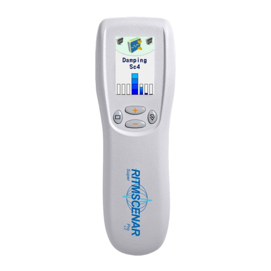
Page 24: Setting The Damping Mode (Dmp)
Operating Manual Version 7.3-03 of 28.07.20 6.2.4 Setting the Damping mode (Dmp) The Damping modes are the following: Dmp Off Damping Off ( ) is indicated by a long beep; Dmp Sс1 Damping 1 ( ) is indicated by a short beep; Dmp Sс2 ... - Page 25 Operating Manual Version 7.3-03 of 28.07.20...
-
Page 26: Switching Off The Device
Operating Manual Version 7.3-03 of 28.07.20 6.2.7 Setting the Stimulus Gap in a Burst (Gap) To control the gap, you can either press the buttons ‘step by step’ or press and hold the appropriate button (this way is faster). Int 1 , the parameter has no sense, though it can still be controlled, and then, when you will be increasing the intensity, the device... -
Page 27: Setting The Automatic Turn-Off Time (Aoff)
Operating Manual Version 7.3-03 of 28.07.20 6.3.1 Setting the Automatic Turn-Off Time (AOff) AOff menu item enables or disables automatic turn-off of SCENAR. AOff When the is set to , the automatic turn-off is disabled. (At- tention! This may cause faster battery exhaustion when you leave the device switched on for a long time). -
Page 28: Setting The Screen Contrast (Cont)
Operating Manual Version 7.3-03 of 28.07.20 6.3.3 Setting the Screen Contrast (Cont) Cont menu item allows to control the picture contrast. 6.3.4 Setting the Default Screen Direction (Save Scr) Save Scr menu item allows to save the current direction of the picture on the screen as default. -
Page 29: Maintenance Service
Operating Manual Version 7.3-03 of 28.07.20 7 MAINTENANCE SERVICE The device shall be serviced and repaired only by the manufacturer. 8 TROUBLESHOOTING 8.1 If the device is not operating properly, identify the problem and refer to the following trouble shooting chart for suggested solutions as indicated in the following Table 4. - Page 30 Operating Manual Version 7.3-03 of 28.07.20 Continue table 4 Fault Possible cause Troubleshooting method There is no energy on The add-on elec- Replace the electrode. the add-on electrode, trode malfunc- while the energy on the tion. built-in electrode is felt. There is no con- Check the connection between tact between the...
-
Page 31: Warranty
Operating Manual Version 7.3-03 of 28.07.20 9 WARRANTY 9.1 The manufacturer guarantees that the device complies with this document when operated properly. 9.2 Warranty period is 24 months from the date of purchase. 9.3 In case of malfunction during the warranty period the device with this Operating Manual shall be returned to the manufacturer. -
Page 32: Transportation And Storage
Operating Manual Version 7.3-03 of 28.07.20 10 TRANSPORTATION AND STORAGE 10.1 The transportation of the devices to a customer is carried out by all kinds of covered vehicles, except the plane compartments that have no heating, at the air temperature from –50 to +50 C and relative humidity not to exceed 100 % at a temperature of 25 C with a protection from a direct atmospheric precipitation. -
Page 33: Annex 1
Operating Manual Version 7.3-03 of 28.07.20 ANNEX 1 Guidance and manufacturer's declaration – electromagnetic compatibility (EMC) Intended healthcare environment – Professional Emissions — Classification Standard EN 55011 (idt CISPR — Class A or B — Group 1 or 2 Conducted RF Emissions NOTE 1 Radiated RF Emissions PASS... - Page 34 Operating Manual Version 7.3-03 of 28.07.20 Guidance and manufacturer's declaration – electromagnetic compatibility (EMC) NOTE 4) SIP/SOPs whose maximum cable length is less than 3m in length are excluded. NOTE 5) This test applies only to output lines intended to connect directly to outdoor cables.
Need help?
Do you have a question about the RITMSCENAR Super Pro v.2 and is the answer not in the manual?
Questions and answers