
Subscribe to Our Youtube Channel
Related Manuals for Talex MULCHER ECO

Summary of Contents for Talex MULCHER ECO
- Page 1 Z-908 FLM 100;135;150;150H;180;200;220;180 H;200H;220H MULCHER ECO Models: 100; 135; 150; 150H; 180; 180H; 200; 200H; 220; 220H...
- Page 2 Z-908 EKO SHREDDER IT IS STRICTLY FORBIDDEN TO USE THE SHREDDER WHILE NON- OPERATORS ARE WITHIN LESS THAN 50 M FROM THE DEVICE Page...
-
Page 3: Table Of Contents
Z-908 EKO SHREDDER TABLE OF CONTENTS Index DEVICE IDENTIFICATION DATA: ............Błąd! Nie zdefiniowano zakładki. INTRODUCTORY REMARKS .............. Błąd! Nie zdefiniowano zakładki. Read the manual carefully ............Błąd! Nie zdefiniowano zakładki. 2.1. Machine purpose ................Błąd! Nie zdefiniowano zakładki. 2.2. Important provisions concerning purchase procedure .... -
Page 4: Device Identification Data
Z-908 EKO SHREDDER DEVICE IDENTIFICATION DATA Producer name, production year, and serial number of the machine are provided in the nameplate located on the body of the shredder. The nameplate incorporates the name and address of the producer, production year, machine symbol, serial number, and the KJ label. The dealer or the producer shall provide all information concerning the machine and the clarification of the data included in this manual. -
Page 5: Warranty
Z-908 EKO SHREDDER 2.4. Warranty Warranty terms are provided in the warranty form. The careful lecture of this document is one of the obligations of the operator. The failure to comply with the regulations on proper exploitation of the device will lead to the decrease in its performance, increase in the malfunction risk, and the fact of the warranty being deemed null and void. -
Page 6: Working Elements Of The Machine
Z-908 EKO SHREDDER ADJUST the movement speed to the current road conditions. Do not drive too fast! NOTE – while turning, the machine may lean backwards or to the sides. 3.3. Working elements of the machine Before using the shredder, check if the blades are properly attached. ... -
Page 7: Equipment And Spare Parts
Z-908 EKO SHREDDER Only „B” safety class jointed telescopic shafts with the following parameters should be used: transferred torque 610 Nm, length (minimal, between the axes of the joints) 710 mm. 3.8. Equipment and spare parts Following equipment is provided together with the shredder: 1. -
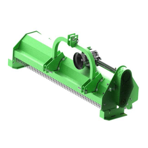
Page 8: 3.10. Construction And Mode Of Operation
EKO SHREDDER 3.10. Construction and mode of operation Construction of the shredder is presented in figure 1. Body (1), Working shaft (2), Driving shaft (3) Bevel gear (4) Gear cover (5) Sliding chute (6) ... - Page 9 The shredder is attached to the three-point hitch of the tractor. The working shaft (3) is powered by the PTO of the tractor via the jointed telescopic shaft, bevel gear (4) and belt drive. Working elements of the machine are blades or beaters situated on the working shaft. The latter is located inside the body.
-
Page 10: Operation
EKO SHREDDER OPERATION 4.1. Attaching the shredder to a tractor The machine compatible with II class agricultural tractors. In order to keep the longitudinal balance and maneuverability of the machine, the front axes of the used tractor shall be loaded with additional weights (being parts of tractor’s equipment). The device is attached to the vehicle by means of three-point hitch (TPH): ... -
Page 11: Starting Work
4.2. Starting work Switch on the drive of the machine. Only after reaching the recommended rotational speed (540 RPM on the PTO), can the device be used for shredding. Driving speed should be adjusted to the terrain and the type of material to be processed. -
Page 12: Belt Tightness
EKO SHREDDER 5.2. Belt tightness Before increasing the tightness of the belts, the inspection window should be open. In order to do so, unscrew two M8 screws (1). Afterwards, loosen the M14 screw (2) located in the inspection hole. The next step is to loosen the M12 nut (4) by turning it clockwise. - Page 13 SERVICING, STORAGE, DISPOSAL Every day, after finishing the work, the shredder must be meticulously cleaned and its technical condition must be inspected. The operator should especially pay attention to the wear of blades or beaters. Replace damaged or worn-out parts. Before starting the work, lubricate telescopic parts of the jointed telescopic shaft.
- Page 14 EKO SHREDDER Figure 2 Shredder drive ................................9 Figure 3 Shredder attachment .............................. 10 Figure 4 Lubrication scheme ............................... 121 Figure 5 Belt tightening scheme ............................12 Figure 6 Working shaft assembly scheme ..........................15 Figure 7a Driving shaft assembly scheme ..........................16 Figure 7b Driving shaft assembly scheme ..........................
- Page 15 Figure 6 Working shaft assembly scheme 1 Working shaft 2 Bearing cover 3 UC207 bearing 4 ISO 10511-M14-N self-locking nut. 5 P_D_27x15_3mm spacer 6 Z908 beater 7 M14x90 ISO 4014 screw Page...
- Page 16 EKO SHREDDER Figure 7a Driving shaft assembly scheme Figure 7b Driving shaft assembly scheme Page...
- Page 17 1 Driving shaft 2 ISO 10511-M16-N self-locking nut 3 M16 ISO7089 flat washer 4 UCFL 207 bearing 5 ISO 10511-M12-N self-locking nut 6 Ru_EKO_Wj_10.12a ver.C support 7 M12 ISO 7089 flat washer 8 M12x35 ISO 4014 screw 9 M16x55 ISO 4014 screw Figure 8a Gear Page...
- Page 18 EKO SHREDDER Figure˛8b Gear 1 OWN_1065.00.30 ver.B driving shaft cover 2 T-313J gear 3 O_65.240 nacelle 4 Z-908-04-80-170 pulley 5 S01-00-01-40/80 clutch 6 Tensioner 6a M12 nut 6b M12 washer 6c M12 nut 6d Tensioner body 6e Ru_EKO_Np_04 ver.B washer 6f M14x40 screw 6g 6209 bearing 6h Ru_EKO_Np_03 ver.B tensioner roll...
- Page 19 9 S01-00-01-40.10 clutch 10 UCF 208 bearing + mounting screws; M16x50 screw, M16 nut, M16 washer 11 M10 screw, M10 nut, M10 washer 12 OWN_1065.00.21 ver.B console 13 Ru_EKO_Wp_00 ver.B gear suport + M12x40 screws, M12 extended washers 14 M12x40 screw; M12 extended washer; M12 self-locking nut T-313J gear is filled with 1.5 liter of 80W90 gear oil (widely available on the market;...
- Page 20 EKO SHREDDER Figure 10 Fixed panel attachment scheme 1 Fixed panel upper pin 2 Fixed panel 3 Mounting set: M12x30 screw, M12 washer, M12 self-locking nut 4 Safety pin 5 Fixed panel lower pin Page...
- Page 21 Figure 11 Moving panel attachment scheme 1 Moving panel upper pin + safety pin 2 Moving panel 3 Left guide grip 4 Mounting set: M12x30; M12 flat washer; M12 self-locking nut 5 M20 self-locking nut, M20 flat wahser 6 Cylinder 7 Moving panel lower pin 8 M24 self-locking nut, M24 flat wahser 9 Guide...
- Page 22 EKO SHREDDER Figure 12 Front curtain 1 Safety pin 2 Curtain pole 3 Spacer 4 Chain Page...
- Page 23 Figure 13 Rear curtain 1 Rear curtain cover 2 Ru_EKO_Kt_11 180 ver.B cover assembly 3 Mounting set: M8x16 screw, M8 flat washer, M8 flat extended washer, M8 self-locking nut 4 Ru_EKO_Kt_21 ver.B pin with cotter Page...
- Page 24 EKO SHREDDER Pcs. Z- Pcs. Z- Pcs. Z- Norm or KTM symbol Set or part name 908/180 908/200 908/220 Figure 1 908-01-00-00-00/180 Body 908-01-00-00-00/200 Body 908-01-00-00-00/220 Body Figure 6 908-02-00-00-00/180 Working shaft 908-02-00-00-00/200 Working shaft 908-02-00-00-00/220 Working shaft 908-02-01-00-00 Bearing cover UC 207 Bearing DIN 931...
- Page 25 BX45X45X17 Fan belts 5 Figure 908-05-00-00-00 Cover M8x30 screw Ø12 washer Figure 8 908-06-00-00-00 Sliding chute DIN 933 M10x35 screw DIN 934 M10 nut Figure 9 908-07-00-00-00 Fixed panel DIN 933 M12x30 screw Ø12 washer DIN 126 DIN 985 M12 self-locking nut 908-07-04-00-00 Fixed panel lower pin 908-07-50-00-00...
- Page 26 EKO SHREDDER 908-10-01-00-00/180 Curtain cover 908-10-01-00-00/200 Curtain cover 908-10-01-00-00/220 Curtain cover Ru_EKO_Kt_11 180 ver B Curtain assembly Ru_EKO_Kt_11 200 Curtain assembly ver B Ru_EKO_Kt_11 220 ver B Curtain assembly Ø8 washer DIN 126 DIN 933 M8x16 screw Ru_EKO_Kt_21 ver.B Pin with cotter Page...
- Page 27 COMPLAINT FORM NO. ……………… Name and surname :…......................Address :............................. Postal code :……........................Locality :……..........................Phone no. :…..........................E-mail address :…………………....................Complaint form issuing mode :………...…………………………………………………………….. Faulty product name: ......................... Outlet name :…………….…………………………………………………........Purchase deed - VAT invoice no.......of......20…..Fault/damage description:…………....................
- Page 28 PN-EN ISO 12100-1:2005, PN-EN ISO 12100-2:2005, EN 294:1994, PN-EN ISO 4251-1, PN-EN 745:2002 This Declaration of Conformity shall be deemed null and void if it has been modified without the direct consent expressed TALEX LESZEK JAWORSKI AND PARTNERS GENERAL PARTNERSHIP by the representatives of the...
Need help?
Do you have a question about the MULCHER ECO and is the answer not in the manual?
Questions and answers