Nordic W Series Installation And Service Manual
Liquid to water heat pumps
Hide thumbs
Also See for W Series:
- Product application, installation and service manual (148 pages) ,
- Application, installation & selection manual (110 pages) ,
- Product application, installation and service manual (126 pages)
Table of Contents
Advertisement
Quick Links
Advertisement
Table of Contents

Related Manuals for Nordic W Series


Summary of Contents for Nordic W Series
- Page 1 Installation and Service Manual W-Series Liquid to Water Heat Pumps Single-Stage R410a Model Sizes 12-18 Maritime Geothermal Ltd. info@nordicghp.com P.O. Box 2555, 170 Plantation Road www.nordicghp.com Petitcodiac, NB E4Z 6H4 002507MAN-01 (506) 756-8135 1-Apr-2021 Page 1 002507MAN-01 1-Apr-2021...
- Page 2 SAFETY PRECAUTIONS WARNING: Ensure all access panels are in place and properly secured before applying power to the unit. Failure to do so may cause electrical shock. WARNING: Before performing service or maintenance on the heat pump system, ensure all power sources are DISCONNECTED.
- Page 3 APPLICATION TABLE OUTDOOR INDOOR MODEL FUNCTION REFRIGERANT VOLTAGE COMPRESOR REVISIONS COIL COIL W-12 W-15 W-18 This manual applies only to the models and revisions listed in this table Maritime Geothermal Ltd. has a continuous improvement policy and reserves the right to modify specification data at any time without prior notice .
-
Page 4: Table Of Contents
Table of Contents Tables, Figures, & Documents ........5 Startup Procedure ............34 W-Series System Description Pre-start Inspection ............... 34 ........6 Unit Startup ................35 General Overview ..............6 Startup Record ..............36 1. Heating Mode ..............6 2. Cooling Mode ..............6 General Maintenance ............ -
Page 5: Tables, Figures, & Documents
002252PDG - Two Tank System Piping with a Reversing Heat Pump ........... 19 002288PDG - Two Tank Simultaneous Heating / Cooling ..............20 002506PDG - Space Conditioning & DHW Heating with Two NORDIC Heat Pumps......21 000530PDG - Typical Zone Types for Hydronic Applications ..............22 000608INF - Typical Horizontal Ground Loop Configuration .............. -
Page 6: W-Series System Description
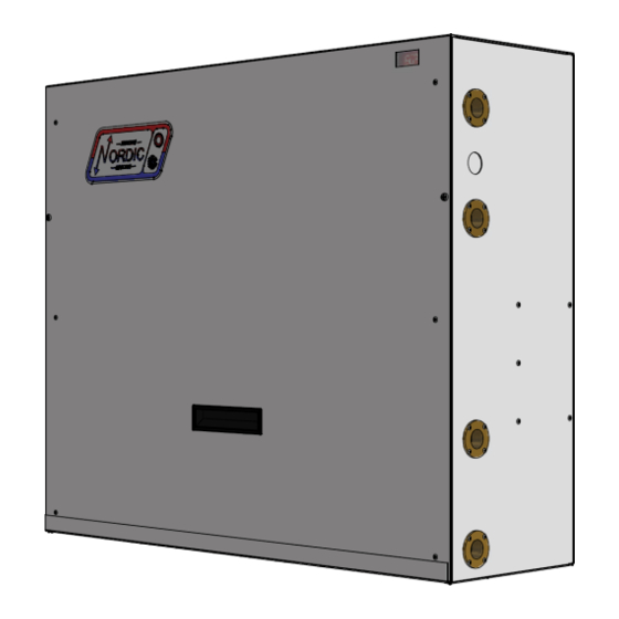
Installation example of a larger (W 25-80) Nordic water to water heat pump 1-Apr-2021 Page 6... -
Page 7: W-Series Sizing
W-Series Sizing Heat Pump Sizing necessary to consult the more detailed performance tables later in the section for heat pump output at a different Entering Liquid The following table is a rough guideline as to the size of Temperature (ELT). space each heat pump size can handle for ground loop (closed In cooling dominant climates, the heat pump should be loop) installations. -
Page 8: Installation Basics
(groundwater) installation: FROM MARITIME GEOTHERMAL FROM MARITIME GEOTHERMAL • W SERIES HEAT PUMP • W SERIES HEAT PUMP • BUFFER TANK W/ELEMENTS __kW • BUFFER TANK W/ELEMENTS __kW • EXTERNAL AQUASTAT (ONLY FOR HEAT/COOL AUTO •... -
Page 9: Wiring
Wiring Power Supply Connections Outdoor Loop Pump Module Wiring (Ground Loop Only) Power supply for the heat pump from the breaker panel is supplied to the unit via a 0.875” knockout. There are also two The heat pump has provisions for connecting the circulator 0.875”... -
Page 10: Control Requirements
Control Requirements Internal Aquastat Operation Since an aquastat is built into the heat pump, no external controls are normally required. The aquastat comes with a probe with 96” (8 ft / 2.4 m) of wire, which should be extended through the knockout on the right side of the cabinet and placed in a dry well near the top of the buffer tank. -
Page 11: Safety Controls
Safety Controls The compressor will not be allowed to start if a ‘fault’ con- The heat pump has 3 built in safety controls which are dition exists. A ‘fault’ occurs if either one of the pressure con- designed to protect the unit from situations which could damage trols exhibits an open circuit. - Page 12 1-Apr-2021 Page 12 002507MAN-01...
-
Page 13: 002508Cdg - Typ. Aux Heat & Circ. Wiring W/Int. Aquastat . 12 002375Qss - Altsource Tanks: Getting Started
1-Apr-2021 Page 13 002507MAN-01... -
Page 14: 002067Cdg - Typical Zone Wiring (Heating Only)
1-Apr-2021 Page 14 002507MAN-01... -
Page 15: 002509Cdg - Typ. Control & Zone Wiring (Htg & Cooling)
1-Apr-2021 Page 15 002507MAN-01... -
Page 16: Piping
Piping Indoor Loop Outdoor Loop The connections for the Indoor Loop circuit are 3/4” The connections for the Outdoor Loop circuit are 3/4” brass female NPT. They are labelled as INDOOR IN and brass female NPT. They are labelled as OUTDOOR IN and INDOOR OUT. -
Page 17: 002366Pdg - Recommended Hydronic Buffer Tank Piping
1-Apr-2021 Page 17 002507MAN-01... -
Page 18: 002367Pdg - Auxiliary Boiler Piping
1-Apr-2021 Page 18 002507MAN-01... -
Page 19: 002252Pdg - 2-Tank System With A Reversing Heat Pump
1-Apr-2021 Page 19 002507MAN-01... -
Page 20: 002288Pdg - 2-Tank Simultaneous Heating/Cooling
1-Apr-2021 Page 20 002507MAN-01... -
Page 21: 002506Pdg - Space Cond. & Dhw Htg W/2 Heat Pumps
1-Apr-2021 Page 21 002507MAN-01... -
Page 22: 000530Pdg - Typical Zone Types
1-Apr-2021 Page 22 002507MAN-01... -
Page 23: Ground Loop Installations
Ground Loop Installations Refer to diagrams 000608INF & 000609INF at the end of Adjust the circulator pump module valves to connect the this section for typical ground loop configurations. They are for purge cart to the ground loop. Begin pumping water through the reference only, and should not be used to replace formal train- ground loop, ensuring that the intake of the pump stays ing and computerized loop design. -
Page 24: Adding Antifreeze Solution
Once the lines have been filled and no more air bubbles are TABLE 12 - Volume of fluid per 100 ft. of pipe appearing in the line, adjust the circulator pump module valves to circulate water through the heat pump using the same Volume /100ft. -
Page 25: 000608Inf - Typical Horiz. Ground Loop Configuration
1-Apr-2021 Page 25 002507MAN-01... -
Page 26: 000609Inf - Typical Vert. Ground Loop Configuration
1-Apr-2021 Page 26 002507MAN-01... -
Page 27: 000906Cdg - Circulator Pump Module Installation
1-Apr-2021 Page 27 002507MAN-01... -
Page 28: 000629Pdg - Pump Module Inst - 2 Units On 1 Loop
1-Apr-2021 Page 28 002507MAN-01... -
Page 29: Open Loop Installations
Open Loop Installations Well Water Temperature tween the pumping fluid level and the pump intake) would con- tribute linearly to the flow rate should a larger pump be installed. The temperature of the well water should be a minimum of 41°F (5°C), and should normally be 45+°F (7°C+). -
Page 30: Water Valve
will not necessarily be pumped into the same aquifer, depend- Figure 2: Open Loop Accessories & Tools ing on underground conditions. The return well must be able to supply at least the same quantity of water as the amount you Cumulative Water wish to inject into it, preferably much more, since injection ca-... -
Page 31: Submersible Pump Selection
Plumbing the Heat Pump Dole valves can emit a ‘whistling’ sound if the pressure drop through them is high. Therefore, they should be placed The port connections for the outdoor loop are brass where the noise will not cause a nuisance, e.g. outside the FPT fittings. -
Page 32: 000907Cdg - Typical Open Loop Installation
1-Apr-2021 Page 32 002507MAN-01... -
Page 33: 000619Inf - Ground Water Disposal Methods
1-Apr-2021 Page 33 002507MAN-01... -
Page 34: Startup Procedure
Startup Procedure The W-Series R410a Startup Record located in this manual is used in conjunction with this startup procedure to provide a de- tailed record of the installation. A completed copy should be left on site, a copy kept on file by the installer and a copy should be sent to Maritime Geothermal Ltd. -
Page 35: Unit Startup
Unit Startup The unit is now ready to be started. The steps below outline the procedure for starting the unit and verifying proper operation of the unit controlled by aquastats. It is recommended that safety glasses be worn during the following procedures. Preparation: 1. -
Page 36: Startup Record
Startup Record Sheet - W-Series Size 12-18 Installation Site Startup Date Installer City Company Province Model Check boxes unless asked to record data. Country Serial # Circle data units. Homeowner Name Homeowner Phone # PRE-START INSPECTION Indoor Loop All shut-off valve are open (full flow available) (Hydronic) Loop is full and purged of air Antifreeze type... -
Page 37: General Maintenance
General Maintenance GENERAL MAINTENANCE SCHEDULE Item Interval Procedure Contactor 1 year Inspect for pitted or burned points. Replace if necessary. Heat exchanger As required* Clean as per HEAT EXHCANGER FLUSING PROCEDURE below. *Generally not required for closed loop systems. Whenever system performance is reduced for open loop. COAXIAL HEAT EXCHANGER FLUSHING PROCEDURE - OPEN LOOP (WELL WATER) STEP 1 Isolate the heat exchanger by closing the valves in the IN and OUT ports to the heat exchanger. -
Page 38: Troubleshooting Guide
Troubleshooting Guide The following steps are for troubleshooting the heat pump. Repair procedures and reference refrigeration circuit diagrams can be found later in this manual. STEP 1: Turn on the ON/OFF switch and verify that the display is present on the internal aquastat. If it is not present, proceed to POWER SUPPLY TROUBLE SHOOTING, otherwise proceed to STEP 2. - Page 39 FAULT CODE TROUBLESHOOTING Fault Possible Cause Verification Recommended Action Fault Code 1 High operating refrigerant Using a refrigeration gauge set, veri- See “High Discharge Pressure” in (High Pressure pressure fy that high pressure approaches or Heating Mode / Cooling Mode Control) exceeds 565psi with compressor on.
- Page 40 COMPRESSOR TROUBLESHOOTING Fault Possible Cause Verification Recommended Action Compressor will Faulty control board. Measuring from C on the terminal Replace control board. not start strip, verify there is voltage at Y, HP1, HP2, LP1, and LP2 but no volt- age present at CC. Faulty run capacitor.
- Page 41 OPERATION TROUBLESHOOTING - HEATING MODE Fault Possible Cause Verification Recommended Action High Discharge Aquastat set too high Verify internal aquastat setting. Lower setting to recommended Pressure max. value of 120°F (49°C). Low or no indoor loop flow Delta T across the indoor loop ports Verify pump is working and sized should be 8-12°F (3-6°C), or com- correctly.
- Page 42 OPERATION TROUBLESHOOTING - HEATING MODE Fault Possible Cause Verification Recommended Action High Suction Leaking reversing valve Reversing valve is the same temper- Tap reversing valve, and switch it Pressure ature on both ends of body, com- back and forth between heating (may appear to mon suction line is warm, compres- and cooling positions.
- Page 43 OPERATION TROUBLESHOOTING - COOLING MODE Possible Cause Verification Recommended Action Fault High Discharge Unit is overcharged High subcooling, low delta T across Remove 1/2lb of refrigerant at a pressure (only possible if unit has water coil. time and verify that the discharge been field serviced and pressure reduces.
-
Page 44: Repair Procedures
Repair Procedures Pumpdown Procedure 1. Connect the refrigerant recovery unit to the heat pump’s internal service ports via a refrigeration charging manifold and to a recovery tank as per the instructions in the recovery unit manual. Plan to dispose of refrigerant if there was a compressor burnout. -
Page 45: Compressor Replacement Procedure
Compressor Replacement Procedure 1. Pump down the unit as per the Pumpdown Procedure above. If there was a compressor burn out (motor failure), the refrigerant cannot be reused and must be disposed of according to local codes. 2. Disconnect piping. 3. -
Page 46: Model Specific Information
Model Specific Information Table 14 - Refrigerant Charge Table 15- Shipping Information MODEL Refrigerant Oil Type WEIGHT DIMENSIONS in (cm) MODEL lb. (kg) W-12 0.60 R410a W-15 0.64 R410a W-12 171 (78) 38 (97) 18 (46) 32 (81) W-18 0.68 R410a W-15 179 (81) -
Page 47: Pressure Drop Data
Table 19: Loop Pressure INDOOR OUTDOOR OUTDOOR OUTDOOR Drop Data (water 104°F) (water 50°F) (15% methanol 32°F) (35% prop. glycol 32°F) 0.13 0.16 0.19 W-12 0.22 0.25 0.28 0.32 0.13 0.16 0.19 0.22 W-15 0.25 0.28 0.32 0.35 0.16 0.19 0.22 W-18 0.25... -
Page 48: Standard Capacity Ratings
Standard Capacity Ratings Standards ARI/ISO/CSA 13256-2 Table 20 - Standard Capacity Ratings - Ground Loop Heating* 60Hz STAGE 1 - ELT 41°F (5°C) EWT 104°F (40°C) * 15% NaCl by Weight Ground Loop Fluid STAGE 2 - ELT 32°F (0°C) Liquid Flow Outdoor Input... -
Page 49: Performance Tables: W-12
Performance Tables W-12-HAC-P-*L R410a, 60 Hz, GKS102KAA OUTDOOR LOOP ELECTRICAL INDOOR LOOP Evap. Flow Delta T Heat Abs. Compressor Input Cond. Flow Delta T Heating (°F) Temp. (gpm) (°F) (°F) (Btu/hr) Current (A) Power (W) (°F) Temp. (gpm) (°F) (°F) (Btu/hr) 4,862 7,434... -
Page 50: Performance Tables: W-15
Performance Tables (continued) W-15-HAC-P-*L R410a, 60 Hz, GKS120KAB OUTDOOR LOOP ELECTRICAL INDOOR LOOP Evap. Flow Delta T Heat Abs. Compressor Input Cond. Flow Delta T Heating (°F) Temp. (gpm) (°F) (°F) (Btu/hr) Current (A) Power (W) (°F) Temp. (gpm) (°F) (°F) (Btu/hr) 5,662... -
Page 51: Performance Tables: W-18
Performance Tables (continued) W-18-HAC-P-*L R410a, 60 Hz, GJS151KAA OUTDOOR LOOP ELECTRICAL INDOOR LOOP Evap. Flow Delta T Heat Abs. Compressor Input Cond. Flow Delta T Heating (°F) Temp. (gpm) (°F) (°F) (Btu/hr) Current (A) Power (W) (°F) Temp. (gpm) (°F) (°F) (Btu/hr) 7,495... -
Page 52: Wiring Diagram (208/230-1-60)
1-Apr-2021 Page 52 002507MAN-01... -
Page 53: Wiring Diagram (265/277-1-60)
1-Apr-2021 Page 53 002507MAN-01... -
Page 54: Refrigeration Circuit - Heating Mode
1-Apr-2021 Page 54 002507MAN-01... -
Page 55: Refrigeration Circuit - Cooling Mode
1-Apr-2021 Page 55 002507MAN-01... -
Page 56: Dimensions
Dimensions 1-Apr-2021 Page 56 002507MAN-01... -
Page 57: Warranty
This warranty is subject to the following conditions: 1. The NORDIC® heat pump must be properly installed and maintained in accordance with MARITIME GEOTHERMAL LTD.'s installation and maintenance instructions.
Need help?
Do you have a question about the W Series and is the answer not in the manual?
Questions and answers