Table of Contents
Advertisement
Quick Links
Advertisement
Table of Contents

Related Manuals for Cattron EliteIQ

Summary of Contents for Cattron EliteIQ
- Page 1 EliteIQ User Manual 9M02-7100-A001-EN...
- Page 2 Cattron Holdings, Inc., or any of its affiliates or agents shall not be liable for incidental or consequential damages of any kind. All Cattron products are sold pursuant to the Terms and Conditions of Sale, a copy of which will be furnished upon request. When used as a tradename herein, Cattron means Cattron Holdings, Inc.
-
Page 3: Table Of Contents
EliteIQ User Manual Contents Description ................................5 Overview ..............................5 1.1.1 Alarm Capabilities ........................5 1.1.2 Control Capabilities........................5 1.1.3 Expandable ..........................6 1.1.4 Communications Capabilities ......................6 Installation and Setup ............................7 Overview ..............................7 What is the Installation Process? ......................7 2.2.1 Unpacking the Equipment ......................7 2.2.2 Mounting the Equipment ......................7 2.2.3 Connecting the Main Power ......................9... - Page 4 Initializing the Modbus Master Interface ....................44 6.2.1 Modbus Master Channel Setup ....................45 6.2.2 Modbus Master Port Setup ....................... 45 Mapping EliteIQ Channels to Modbus Registers ................... 46 PC/Laptop Access ............................. 47 Glossary ................................51 Technical Support ............................. 71...
-
Page 5: Description
Setting local LEDs to alert personnel that channels are in alarm • So, the EliteIQ is your complete 24-hour a day, 7-day a week monitoring and notification system that allows you to turn your operations into unattended operations. 1.1.2 Control Capabilities The EliteIQ is a complete stand-alone controller capable of turning relays on and off based on a number of conditions. -
Page 6: Expandable
Supports 8-48 physical input channels • Relay expansion using 4-channel cards • 1.1.4 Communications Capabilities The EliteIQ’s communication capabilities include the following: • Web-based monitoring service to deliver alarm notification, historical charting of data and reporting • Modbus Master to distributed sensors... -
Page 7: Installation And Setup
• 2.2.1.1 Operating Environment The EliteIQ should be installed in an environment that is not subject to shock or vibration. The operating temperature of the EliteIQ is -40 to 185 ºF (-40 to 85 ºC). 2.2.2 Mounting the Equipment WARNING... - Page 8 EliteIQ User Manual Fiberglass NEMA Enclosure Figure 1: NEMA 4X Enclosure Panel Mount Enclosure Figure 2: Panel Enclosure Mounting Dimensions 9M02-7100-A001-EN Version B...
-
Page 9: Connecting The Main Power
2.2.3 Connecting the Main Power The EliteIQ operates on 100 to 240 VAC, 50/60 Hz, using 1.5 A at 115 VAC or 0.7 A at 230 VAC. There are no selections required by the user to select the input power. The main AC is connected to the EliteIQ using the AC terminal block located inside the unit. - Page 10 INTERNAL SURGE AND LIGHTNING PROTECTION TO BE INEFFECTIVE. 2.2.3.3 Optional DC Power Connection For applications where standard AC power is not available, the EliteIQ can be powered by an external DC power source, as described in the following table. 9M02-7100-A001-EN...
-
Page 11: Connecting The Input And Output Cards
If no lights on the EliteIQ turn on when the power switch is put in the ON position, this fuse should be checked. Be sure to disconnect the EliteIQ from the primary power source prior to checking this fuse. - Page 12 There are three types of Input and Output cards for the EliteIQ: Digital Inputs, Analog Inputs and Relay Outputs. Each of these cards can be placed in any of the I/O slots of the EliteIQ. The slots are numbered from 10 through 60.
- Page 13 Note that each connector has two terminals, (IN) and (+V). If all of your inputs are originating from a location near each other, you can wire all of the (+V) signals together on the EliteIQ connector and take a single (IN) signal to...
- Page 14 Figure 9: Daisy-Chained – Direct Voltage Input and Contact to Ground Wiring The 24 VDC signal (+V) must be daisy-chained to all common points on the sensors that are being monitored to supply a power signal that can be sensed by the EliteIQ. 9M02-7100-A001-EN...
- Page 15 The (-) return on each Analog Input channel is connected to ground. If you are going to daisy-chain a current loop, then the EliteIQ connection must be the last in the loop. Each input channel is independent of any other input channel. A fault on one channel does not affect the conversion result on the other channels.
- Page 16 EliteIQ User Manual Cattron recommends that you use medium-gauge wire (18 to 22 AWG) twisted pair. Figure 11: Analog 4-20 mA and Voltage Connections for Analog Input Cards 9M02-7100-A001-EN Version B...
- Page 17 2.2.4.4 Relay Wiring Each relay output board has terminal connections for four relays. The EliteIQ can be configured for a maximum of 24 relays, each of which is independently controlled either directly or under alarm conditions. Each board is equipped with two quick-disconnect plugs that allow for easy connection of sensor wires. There are three connections for each relay: Normally Open (NO), Common (C) and Normally Closed (NC), as labeled on the board bracket.
-
Page 18: Testing The System
Turning on the EliteIQ The power switch for the EliteIQ is located on the processor board mounted on the back of the front panel. To turn the power on, open the front panel and move the slide switch (SW1) to the ON position. - Page 19 EliteIQ User Manual Figure 14: EliteIQ Board Connections 9M02-7100-A001-EN Version B...
- Page 20 The main motherboard also includes a 3 V lithium battery to maintain the real-time clock and portions of the SRAM memory. Each battery provides 10 years of use. If the date and time in the EliteIQ are not retained when power is turned off then on, this battery needs replacing.
- Page 21 EliteIQ User Manual Verification that the backup battery is properly connected is accomplished by requesting the status of the System Channel for the battery, channel 02. WARNING THERE IS THE RISK OF EXPLOSION IF THE BATTERY IS REPLACED WITH THE INCORRECT TYPE.
-
Page 22: Quick Start
• In addition, this section lists the default values that come shipped with the EliteIQ. Default Values The EliteIQ is shipped with factory-configured default settings that make it usable when it is installed, as shown in the following table. Parameter... -
Page 23: Quick Programming Steps
Quick Programming Steps While there are a large number of options available in the EliteIQ, it is very easy to get the system up and operating if you first decide on what conditions are being monitored and what relays, if any, are going to be controlled. -
Page 24: Testing The System
This test assumes the following: The EliteIQ has primary power • The EliteIQ has a digital input wired into Channel V+ and IN on the digital input card • The LED for channel 11 is solid green, indicating that it is enabled •... -
Page 25: Operation
The EliteIQ provides real-time display and alarm notification of monitored conditions. Monitored conditions are connected to the EliteIQ as current or voltage signals to 8-channel analog input cards and dry or wet contacts into the digital inputs. There can be up to six 8-channel cards in a system for a total of 48 physical points. -
Page 26: How To Use The Keypad
Red Keys Puts the EliteIQ into PROGramming mode. When at the top level of the menu, puts the EliteIQ into RUN mode. When not at the top of the menu, it functions as a ‘2’. System Status Enables activation/deactivation Relay Lists of specified relays. -
Page 27: How To Enter Text For Names
4.1.3 How to Enter Text for Names The EliteIQ allows the user to enter names for the Site (Unit) and for each channel. Entering names is very similar to entering names on most cell phones that are used today. -
Page 28: Run Mode Operations
4.1.4 RUN Mode Operations The EliteIQ monitors all inputs and evaluates all alarm conditions when it is in the RUN mode. While in this mode, the EliteIQ automatically displays all enabled input channels. Enabled channels are those that have a green shown on the analog or digital input card or on a Modbus Master channel. - Page 29 EliteIQ User Manual 9M02-7100-A001-EN Version B...
-
Page 30: Viewing The Display
EliteIQ User Manual Viewing the Display When in RUN mode, the EliteIQ shows the following display: 4.2.1 Automatic Alarm Screen When any channel goes into alarm, the display automatically changes to show the current conditions of those channels. If any channel goes into alarm, the Alarm Screen is automatically displayed. -
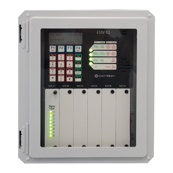
Page 31: How Alarms Are Presented Via Leds
EliteIQ User Manual 4.2.2 How Alarms are Presented via LEDs When a channel goes from the normal state to the alarm state, one or more of several notification methods are activated. Alarms can be presented in any of the following ways:... -
Page 32: Physical Channel Numbering
EliteIQ User Manual Channel Channel Name Function Default Settings Number Communication Monitors Modbus RTU Master Alarm Delay is 60 seconds. communications to Slave devices. If No Relay List is set. communication is lost for a period of time, then this channel and other Modbus channels go into alarm. -
Page 33: Modbus Channel Numbering
User Manual 4.2.5 Modbus Channel Numbering When the EliteIQ is a Modbus Master, channels are ‘logical’ instead of physical. Modbus channels are still Slot oriented and numbered like physical channels. To read or write in a value from/to a Modbus Slave device, do the following: Configure a Slot in the EliteIQ to be a Modbus slot •... - Page 34 EliteIQ User Manual User Input Display Shows View Channel display F1 to return to the RUN MODE display F4 to go to the Scrolling Channel display Enter a channel number to go to the View Data display. View Data F1 to go to Exit this display and return to View Channel display...
-
Page 35: Acknowledging Alarms
F3 to display the next channel in alarm F4 to pause on this specific channel If the EliteIQ is a Modbus Master and there is a communications error with reading a channel, then channel 06 (Communications channel) goes into alarm, if the Channel Mode is Call on Alarm and the Alarm Delay has expired. - Page 36 EliteIQ User Manual 4.2.7.1 From the Front Panel At the front panel, press the key to acknowledge a channel that is in alarm. All channels that are in alarm are Clear acknowledged at the same time. The blinking LED channel indicator changes to steady On, indicating that the specific channel is still in alarm, but it has been acknowledged.
-
Page 37: Programming Mode From The Keypad
EliteIQ User Manual PROGramming Mode from the Keypad Overview PROGramming mode allows the user to do the following: Change system wide settings • Name of the unit Date/Time PROGramming Access Code Change the settings for an input • Low and High limits... -
Page 38: System Wide Settings
EliteIQ User Manual System Wide Settings These settings affect the overall operation of the system. These settings are typically adjusted during the initial installation, but they can be modified at any time. Note: Press the # key to do the following:... -
Page 39: Program Channel Settings
EliteIQ User Manual Keypad Entry - Reset Counters Program Channel Settings These settings affect the operation of the channel monitoring a sensor. These settings are typically adjusted during the initial installation, but they can be modified at any time. Note:... - Page 40 EliteIQ User Manual Keypad Entry Input Type – Specify if input is 4-20 mA or voltage ▼ Decimal Position – # of digits to the right of the decimal position ▼ Engineering Units – Engineering units for this input Scale Input signal (yes or no) –...
-
Page 41: Relay Outputs
Rate of Change Period (0 – 60 minutes) 3 – Report Only - Alarm Delay 0 – as fast as the EliteIQ can issue an alarm - Continue Notification if Return to Normal - Relay List Relay List to activate/deactivate going in/out of alarm 5.3.2 Relay Outputs... -
Page 42: Digital Inputs
▼ Totalizer Limit (0 – 999999999) ▼ Duration Limit (0 – 999999999) ▼ Limit Reset Period (0 – 999999 seconds) - Alarm Delay 0 – as fast as the EliteIQ can issue an alarm (about 210 ms) 9M02-7100-A001-EN Version B... -
Page 43: Relay List Setup
EliteIQ User Manual Keypad Entry - Continue Notification if Return to Normal - Relay Relay to activate/deactivate going in/out of alarm Relay List Setup When any input goes into an alarm condition, a list of relays can be controlled. Each list can contain up to nine physical relays (located in the same controller or communicated with via Modbus). -
Page 44: Modbus Rtu Master
The I/O in the Modbus Slave can be any combination of analog (holding registers) or digital points (coils). Values that are read from the Modbus Slave are interpreted by the EliteIQ the same as if they were physical I/O in the EliteIQ. -
Page 45: Modbus Master Channel Setup
6.2.1 Modbus Master Channel Setup When you enter a channel number that is enabled as a Modbus channel, you see the display to the right. Keypad Entry Slave ID (0 indicates read from an EliteIQ channel) ▼ Register Type ▼ Register Number Enter Selection [ 0 –... -
Page 46: Mapping Eliteiq Channels To Modbus Registers
▼ Max Timeout ▼ RS-485 Mapping EliteIQ Channels to Modbus Registers I/O channels in the EliteIQ are mapped to Modbus registers by providing three pieces of information, as follows: Modbus ID – ID of the Modbus Slave • Register Type –... -
Page 47: Pc/Laptop Access
User Manual PC/Laptop Access The EliteIQ can be accessed from a PC or laptop to view the current status of all channels, view the event log, modify programming, etc. The connection to the EliteIQ is via the serial RS-232 port 2 or port 3. - Page 48 EliteIQ User Manual Command (1 – View Config) ******** View Config ******** 1) Site 2) Options 3) CELL 4) FTP 5) Report 6) Serial 7) Report Flags 8) Relay Lists 9) Channels V) Virtual Chan A) All ...> (enter an option from 1 to A) Option (1 –...
- Page 49 EliteIQ User Manual Option (4 – FTP Config) FTP Config (4) Report Type (1): None Put Path (2): ./ Get Path (3): ./ Get Filename (4): Port (5): 21 (6): antxftp.com Username (7): ftpuser@antxftp.com Password (8): 11okeypoe3 Mode (9): Passive Option (6 –...
- Page 50 EliteIQ User Manual Channel Config (9) -- 0 9 -- AIN8 DIN8 empty empty empty DOUT4 empty empty empty Slot # [0-9]: 4 (viewing the Analog Input configuration) ------------------------------------------------------------------- Type/Number : AIN/41 Name (1): Chan 41 Mode (2): Report Only [4]...
-
Page 51: Glossary
Accumulated time is reported as Days, Hours, Minutes and Seconds. Acknowledge Alarms Locally: Press the ACK key on the keypad while the EliteIQ is in RUN mode. Acknowledge Input A digital input channel can be used to acknowledge alarms. When this channel Channel goes into the Non-Normal condition, it will acknowledge all active alarms. - Page 52 EliteIQ User Manual Item Description Alarm Mode 0 This mode defines a normal region that is above the Low Limit and below the High Limit. Alarm Mode 2 This mode defines a normal region that is above a Low and High Limit. The Low Limit is below the High Limit.
- Page 53 EliteIQ User Manual Item Description Alarm Mode 3 This mode defines a normal region that is below a Low and above a High Limit. Alarm Mode 4 This mode defines two normal operating regions, one above a High Alarm Limit and one below a Low Alarm Limit.
- Page 54 4-20 mA or 1-5 V. These signals are connected to Analog Input cards and programmed to provide values in engineering units. EliteIQ operates on analog inputs in engineering units, not counts. Since you are measuring in engineering units, this makes it easier to specify the alarm limits that you use.
- Page 55 Battery Backup The standard 12 VDC internal backup battery maintains operating power to the EliteIQ for a minimum of 24 hours at 86°F in case of primary power loss. The switchover to battery operation is automatic; no operator intervention or reprogramming is required.
- Page 56 Bits A Read Packed Bits operation reads a 16-bit word from the Modbus Slave device. The EliteIQ can extract a single bit from a Holding Register and use that as the input to a digital input channel. The EliteIQ numbers the bits from 1 to 16, with 1 being the least significant bit.
- Page 57 Clear the current value being entered from the keypad. Shown on the display and in reports. Indicates there is a Communications error between the EliteIQ and a Modbus device. Confirm that the cable is connected, the baud rate is correct, and the Modbus ID and register number are correct.
- Page 58 Channel is not scanned or evaluated for alarms. Channel LED is not lighted. Disarm DISARMed mode is signified by a red blinking RUN LED. In this mode, the EliteIQ is monitoring all inputs but will NOT perform any alarm operations including turning on/off relay.
- Page 59 22 – ppm 34 – % lel 11 – gallons / hour (*) 23 – watts (*) If selected, the EliteIQ will automatically compute the total flow. Enter (#) Key Enter the current entry. Backup one level in the menu.
- Page 60 Event Log The event log stores the 1000 most recent events that have occurred in the EliteIQ. The information that is stored includes alarm conditions, call outs, and call ins. All events are logged with the following information: <Date and Time> <Event logged information>...
- Page 61 The maximum amount of time the EliteIQ waits for another character to be received after the last one was received. Max Timeout The maximum amount of time the EliteIQ waits for a response when it transmits a message. Maximum Counts The maximum number of counts read from a Modbus Holding Register.
- Page 62 For all Analog Input channels that are 0-20 mA or 4-20 mA. Defines a limit that if the input falls below, the EliteIQ will assume the input is an Open Loop. When an Open Loop condition exists, channel 07 (System Fault) goes into alarm.
- Page 63 2 – Not used 3 – Modbus Master 4 – Not used Ports The available ports in the EliteIQ are as follows: 0 – UART used for LTE modem 1 – Port 2 2 – Port 3 Positive Rate of Change...
- Page 64 2 Hz with a required duty cycle of 50%. This means that the signal coming into the EliteIQ must be active (high or low) for 250 ms in order for it to be counted as a pulse.
- Page 65 Register Number. For example, a PLC may reference register 40100. In the EliteIQ, this would be a Read Holding and Register Number 100. To read a channel from the same EliteIQ, the register number is based on the channel number in the EliteIQ:...
- Page 66 EliteIQ User Manual Item Description Relay List A list of up to nine physical relays that can be controlled when any input changes from the Normal to Non-Normal condition or from the Non-Normal back to the Normal condition. A relay list consists of the following:...
- Page 67 Note: This is only written to permanent memory when the EliteIQ is put into RUN mode. If you do not want to reset the system, turn the EliteIQ off before returning to RUN mode. Hidden underneath this function is a method to Backup and Restore a complete programmed configuration.
- Page 68 Pressing the SCRL key cycles the display through all enabled channels. Serial Port The EliteIQ has three serial ports, Port 1, Port 2 and Port 3. Port 1 is reserved for the LTE cellular modem. Ports 2 and 3 are on DB9 connectors if using RS-232 or a 6-pin connector if using RS-485.
- Page 69 There are 2 System Delays, as follows: Program to Run Mode Delay Specify the amount of time that must elapse before the EliteIQ automatically goes from PROGramming mode to RUN mode if the system is inadvertently left in the PROGramming mode.
- Page 70 EliteIQ User Manual Item Description Zero Scale The scaling value in engineering units that corresponds to the lowest analog reading. This value can be positive (+) or negative (-). When entering this value, pressing the ‘*’ key twice toggles between (+) and (-).
-
Page 71: Technical Support
EliteIQ User Manual Technical Support For remote and communication control systems support, parts and repair, or technical support, visit us online at: www.cattron.com/contact. This product was formerly produced by Antx, Inc. 9M02-7100-A001-EN Version B... - Page 72 Due to continuous product improvement, the information provided in this document is subject to change without notice. Cattron Support For remote and communication control systems support, parts and repair, or technical support, visit us online at: www.cattron.com/contact Cattron North America Inc., 655 N River Rd NW, Suite A, Warren, OH 44483 9M02-7100-A001-EN Version B...
Need help?
Do you have a question about the EliteIQ and is the answer not in the manual?
Questions and answers