
Related Manuals for Leviton A8810-41M


Summary of Contents for Leviton A8810-41M
- Page 1 Energy Management Hub and 3-Phase Meter EMX Data Acquisition System Cat. No. A8810-41M/41R Installation Guide DI-000-A8810-00A...
-
Page 3: Table Of Contents
TABLE OF CONTENTS Warnings ..............................1 Cautions ...............................1 1 Getting Started ..........................2 2 Site Location and Providing Power ....................4 3 Internal Component Configuration and Operation ...............7 4 Final Steps ............................. 11 5 Standard Statements ........................15... -
Page 4: Warnings
WARNINGS AND CAUTIONS WARNINGS: • TO AVOID FIRE, SHOCK OR DEATH, turn off all power supplying equipment before working on or inside the equipment. Use a properly rated voltage sensing device to confirm power is off. • RISK OF ELECTRIC SHOCK, EXPLOSION, OR ARC FLASH. CAREFULLY READ AND FOLLOW INSTRUCTIONS: •... -
Page 5: Getting Started
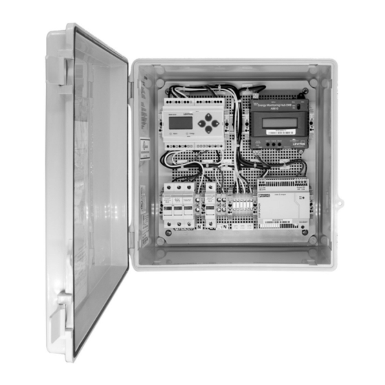
Please report any damage to your product to your vendor immediately. Packing material must be removed for operation. Please discard, recycle, or reuse these materials appropriately. Technical Support For technical support, contact Leviton at 800-959-6004, or via email at meters@leviton.com... - Page 6 1 GETTING STARTED 1.3 Product Overview The EMX panel comes fully assembled, wired and ready for installation. Power Meter – Series 4100 Energy Monitoring Bi-Directional Hub - A8810 (4DUMR split core or Rogowski coil versions) Separate 3-Phase (meter reference voltage) and Single- Phase (system Power Supply power) fused AC...
-
Page 7: Site Location And Providing Power
2 SITE LOCATION AND PROVIDING POWER 2.1 Mounting the Enclosure 2.1.1 Mount the enclosure in a location according to and compliant with local electric code. 2.1.2 Mounting Tabs and screws are provided with the enclosure. The provided screws are intended to be used to mount the tabs to the enclosure. User to provide additional mounting hardware as needed. - Page 8 2 SITE LOCATION AND PROVIDING POWER 2.2 Connecting Input Power 2.2.1 Per local electrical code and site specifications connect power to voltage sense input and panel power input. 2.2.2 There are separate power inputs for meter reference voltage and panel power to allow the hub and meter to remain powered if the circuits being monitored need to be off.
- Page 9 2 SITE LOCATION AND PROVIDING POWER 2.4 Observe correct CT orientation Diagram 1: 1-Phase Line-to-Neutral Diagram 2: 1-Phase Line-to-Line 2-Wire System 1CT 2-Wire System 1CT 1L + 1n) Use System Type 10 ( Use System Type 11 ( White White Black Black X2 A...
-
Page 10: Internal Component Configuration And Operation
3 INTERNAL COMPONENT CONFIGURATION AND OPERATION 3.1 Introduction The Leviton EMX comes with multiple internal components that are essential to operation. The following describes these components and outlines basic installation instructions. 3.2 Phoenix Contact Power Supply Description: The Phoenix Power Supply provides DC power to the components within the cabinet, and, if needed, external devices that you may wish to power. - Page 11 3 INTERNAL COMPONENT CONFIGURATION AND OPERATION 3.3.1 General Set Up Screen Navigation Instructions 3.3.1.1 Press + or – repeatedly until SETUP screen appears. 3.3.1.2 Press to get to the PASWD screen. 3.3.1.3 Press to move through the digits. Use the + to – buttons to enter your desired password (the default is 00000).
- Page 12 3 INTERNAL COMPONENT CONFIGURATION AND OPERATION Rogowski “Rope” CT Instructions 3.3.3.5 From S COM screen, press – to Navigate to the S CT (Set Current Transformer) Setup screen. 3.3.3.6 Press to go to the CT SZ screen and through the digits. Use + or –...
- Page 13 3 INTERNAL COMPONENT CONFIGURATION AND OPERATION 3.4 Commissioning the A8810 Engergy Monitoring Hub Description: The A8810 is the data hub used to collect data from a variety of devices power meters, gas meters, water meters, and other sensors. This site data is consolidated in the EMH and using the user defined upload channels, it is uploaded to cloud based software like Building Manager Online, to an FTP site, or as a .CSV file.
- Page 14 3 INTERNAL COMPONENT CONFIGURATION AND OPERATION 3.5 Step by Step Commissioning The following is a basic setup to enable Remote Access to the A8810 Hub to complete the configuration process. Confirm the DAS is properly connected to the computer or a LAN, and both are powered on. 3.5.1 DHCP Enabled Mode 3.5.1.1 Confirm that DHCP is enabled on the computer.
- Page 15 3 INTERNAL COMPONENT CONFIGURATION AND OPERATION 3.5.1.6 Enter the desired admin user password in both boxes and click the Apply button. 3.5.1.7 A Thank You message will be displayed, confirming that the password was successfully set. Click on the line below to proceed to the login screen.
- Page 16 3 INTERNAL COMPONENT CONFIGURATION AND OPERATION 3.5.1.8 To initiate Remote Access • Expand Networking • Select Setup • Check Allow “Remote Access”: • Click Apply 3.5.1.9 Once Remote Access Successfully Connects you will receive the message “R-Access Online”. Record • Serial Number: •...
- Page 17 3 INTERNAL COMPONENT CONFIGURATION AND OPERATION 3.6 Static IP Enabled Mode Confirm the DAS is properly connected to the computer, and both are powered on. 3.6.1. On the EMB Hub, click the “Menu” button to select the “TCP/IP Config” option. 3.6.2 Click the “Select”...
-
Page 18: Final Steps
4 FINAL STEPS 4.1 Final Steps and Support Before leaving the site, please ensure that the following steps have been completed: • Enclosure is mounted and powered per code • AC Power is terminated to local code • Bottom knockouts are appropriately sealed and weatherproofed •... -
Page 19: Standard Statements
LIMITED 5 YEAR WARRANTY AND EXCLUSIONS Leviton warrants to the original consumer purchaser and not for the benefit of anyone else that this product at the time of its sale by Leviton is free of defects in materials and workmanship under normal and proper use for 5 years from the purchase date.
Need help?
Do you have a question about the A8810-41M and is the answer not in the manual?
Questions and answers