
Related Manuals for Water Process Solutions CHEMTUBE 2000


Summary of Contents for Water Process Solutions CHEMTUBE 2000
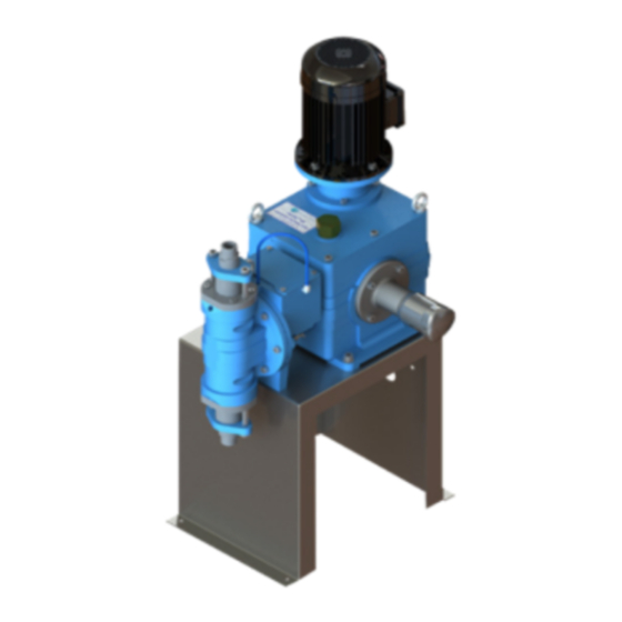
- Page 1 Operation & Maintenance Manual CHEMTUBE® 2000 TUBULAR DIAPHRAGM METERING PUMP Manual No. WPSCH2000MAN...
- Page 2 CHEMTUBE® 2000 TUBULAR DIAPHRAGM METERING PUMP MANUAL NO. WT.430.500.0AA.UA.IM.0813...
- Page 3 EC-DECLARATION OF CONFORMITY Directives covered by this declaration 89/336/EEC Electromagnetic Compatibility Directive, amended by 92/31/EEC & 93/68/EEC 73/23/EEC Low Voltage Equipment Directive, amended by 93/68/EEC 89/392/EEC Machinery Directive, amended by 91/368/EEC, 93/44/EEC & 93/68/EEC Products Covered by this declaration CHEMTUBE® 2000 Tubular Diaphragm Metering Pumps [2", 2.5" & 3"] The products identified above comply with the requirements of the EMC Directive and with the principle elements of the safety objectives of the Low Voltage and Machinery Directives.
- Page 4 EQUIPMENT SERIAL NO........DATE OF START-UP ..........START-UP BY ............Prompt service available from nationwide authorized service contractors. ORDERING INFORMATION In order for us to ll your order immediately and correctly, please order material by description and part number, as shown in this book. Also, please specify the serial number of the equipment on which the parts will be installed.
- Page 5 Also, when the optional Teflon-lined tubular diaphragm is used, the Chemtube 2000 pump is capable of handling a variety of corrosive fluids. When an electric stroke length positioner or variable speed drive is used with the pump, a separate instruction manual covering the particular equipment used will be furnished.
- Page 6 WARNING: TO AVOID POSSIBLE SEVERE PERSONAL INJURY OR DAMAGE TO THE EQUIPMENT, THIS EQUIPMENT SHOULD BE INSTALLED, OPERATED AND SERVICED ONLY BYTRAINED, QUALIFIED PERSONNEL WHO ARE THOROUGHLY FAMILIAR WITH THE ENTIRE CONTENTS OFTHIS INSTRUCTION BOOK. WHEN DEALING WITH HAZARDOUS MATERIAL IT IS THE RESPONSIBILITY OFTHE EQUIPMENT USER TO OBTAIN AND FOLLOW ALL SAFETY PRECAUTIONS RECOMMENDED BYTHE HAZARDOUS MATERIAL MANUFACTURER/SUPPLIER.
- Page 7 THE USE OF UNLISTED PARTS CAN RESULT IN EQUIPMENT MALFUNCTIONS HAVING HAZARDOUS CONSEQUENCES. ADDITIONAL OR REPLACEMENT COPIES OF THIS INSTRUCTION BOOK ARE AVAILABLE FROM: Water Process Solutions Unit 10 Mill Hall Business Estate Aylesford, Kent, ME20 7JZ Phone: +44(0) 1622 719945 Email: enquiries@waterprocesssolutions.com...
- Page 8 VERY IMPORTANT SAFETY PRECAUTIONS (CONT’D) NOTE Minor part number changes may be incorporated into WPS products from time to time that are not immediately reflected in the instruction book. If such a change has apparently been made in your equipment and does not appear to be reflected in your instruction book, contact WPS for information.
- Page 9 PROTECTYOUR EQUIPMENT INVESTMENT MINIMIZE DOWNTIME ORDER A PREVENTIVE MAINTENANCE KIT NOW ... KEEP ONE ON HAND Quality Preventive Dependable Operation Equipment Maintenance Minimum Downtime There’s no question about it. Equipment that is properly maintained is dependable equipment. It will give optimum performance with minimum unscheduled downtime WPS manufactures quality equipment designed for performance and reliability.
- Page 10 Maintenance & Performance PREVENTIVE MAINTENANCE SCHEDULE AND RECORD OF PERFORMANCE This equipment should receive preventive maintenance on a one (1) year cycle.* It is recommended that the following table be used to plan, schedule, and record this important work. Preventive Maintenance Log Schedule Date Date Performed *NOTE: This is the recommended cycle.
- Page 11 Notes On Protective Equipment And Clothing The following Warning appears in several locations in this book. It is general in nature due to the variety of hazardous liquids this equipment is capable of handling. WARNING: WHEN DEALING WITH HAZARDOUS MATERIAL, IT IS THE RESPONSIBILITY OF THE EQUIPMENT USER TO OBTAIN AND FOLLOW ALL SAFETY PRECAUTIONS RECOMMENDED BY THE MATERIAL MANUFACTURER/SUPPLIER.
- Page 12 If the equipment was purchased directly from WPS, contact the office indicated below. UNITED KINGDOM Water Process Solutions Unit 10 Mill Hall Business Estate Aylesford, Kent, ME20 7JZ Phone: +44(0) 1622 719945 Email: enquiries@waterprocesssolutions.com...
- Page 13 Section 1 - Technical Data List Of Contents PARA./DWG. NO. Technical Data Capacity Specifications and Motor Selection High Pressure Effects on Capacity Illustrations Performance Compatibility 430.500.190.010A-F Application Guide for WPS Solution Tanks 430.500.190.010A-F WT.430.500.0AA.UA.IM.0813...
-
Page 14: Technical Data
Technical Data Technical Data PARAMETER SPECIFICATION Hydraulically actuated tubular diaphragm, Type simplex, or double simplex. Service See Dwg. 430.300.190.010A-F Capacities Refer to Power Requirements (paragraph 1.1.1) Maximum Liquid Temperature 180°F for 316SS valves 150°F for Kynar valves 125°F for PVC valves Control Stroke length adjustable -- Manual Optional Electric Positioner Electrical speed --... - Page 15 60 Hz 1725 RPM 50 Hz 1450 RPM Pounds per Square Inch Piston Conncection Stroke Capacity Stroke Capacity Motor Horespower - Induction (Variable) - 1725 RPM Motor Kilowatts - Induction (Variable) - 1450 RPM Size Cartridge Frequency Frequency inches Simplex Double Simplex Simplex Double Simplex...
-
Page 16: High Pressure Effects On Capacity
High Pressure Effects on Capacity This pump has been designed to provide a high degree of repeatability throughout a wide range of pressures. The capacity that can be expected is nearly that of theoretical displacement. As discharge pressure increases, a small decrease in capacity can be expected, approximately 1.0 to 3% per 100 psi. - Page 17 LIQUID REF. NO. 316 S.S HYPALON VITON KYNAR 150 CERAMIC ACETALDEHYDE ACETATE SOLVENTS ACETIC ACID, CRUDE ACETIC ACID, PURE ACETIC ACID (10%) ACETIC ACID (80%) ACETIC ANHYDRIDE ACETONE ACETYLENE ACRYLONITRILE ALUMINIUM CHLORIDE ALUMINIUM HYDROXIDE ALUMINIUM NITRATE ALUMINIUM SULFATE ALUMS AMINES AMINES (FILMINE) B AMMONIA ANYHYDROUS (LIQ.) AMMONIA SOLUTIONS...
- Page 18 LIQUID REF. NO. 316 S.S HYPALON VITON KYNAR 150 CERAMIC BUTYL ALCOHOL BUTYRIC ACID CALCIUM BISULFITE CALCIUM CARBONATE CALCIUM CHLORATE CALCIUM CHLORIDE CALCIUM HYDROXIDE CALCIUM HYPOCHLORITE CALCIUM NITRATE CALCIUM SULFATE CANE SUGAR LIQUORS CARBOLIC ACID (PHENOL) 11,14,57 CARBON BISULFIDE CARBONIC ACID 14,57 CARBON TETRACHLORIDE 13,3...
- Page 19 LIQUID REF. NO. 316 S.S HYPALON VITON KYNAR 150 CERAMIC GLUCOSE GLYCEROL (GLYCERIN) 6,11,27 HEPTANE, HEXANE HYDRAZINE (35%) HYDROBROMIC ACID HYDROCHLORIC ACID (37%) 5,30 HYDROCYANIC ACID HYDROFLUORIC ACID 6,26,25 HYDROFLUOSILICIC ACID 6,25,26,57 HYDROGEN PEROXIDE 31,59 HYDROGEN SULFIDE 11,3 INKS IODINE SOLUTION KEROSENE LACTIC ACID 32,57...
- Page 20 LIQUID REF. NO. 316 S.S HYPALON VITON KYNAR 150 CERAMIC OXALIC ACID PALMITIC ACID PERCHLORIC ACID (10%) PERCHLOROETHYLENE (DRY) PHENOL (CARBOLIC ACID) PHOSPHORIC ACID 6,11,39 PHOSPHORUS TRICHLORIDE PICRIC ACID POTASSIUM BICARBONATE POTASSIUM BROMATE POTASSIUM BROMIDE POTASSIUM CARBONATE POTASSIUM CHLORATE POTASSIUM CHLORIDE 5,41 POTASSIUM CHROMATE POTASSIUM CYANIDE...
- Page 21 LIQUID REF. NO. 316 S.S HYPALON VITON KYNAR 150 CERAMIC SODIUM SULFATE SODIUM SULFIDE 1,48 SODIUM SULFITE SODIUM THIOSULFATE (HYPO) STARCH STEARIC ACID SUGAR SOLUTIONS SULFUR CHLORIDE SULFUR MOLTEN SULFURIC ACID (0-40%) SULFURIC ACID (40-95%) 5,58 SULFURIC ACID (95-100%) SULFUROUS ACID TANNIC ACID TARTATIC ACID 6,44...
- Page 22 NOTES: WARNING: DRIED RESIDUE OF SPILLED PVC TO 100°F, 50%, SS TO 100°F, 50% SOLUTIONS IS EXPLOSIVE. PVC TO 70°F, 10%, SS TO 70°F, 10% SS TO180°F SS TO 70°F, 5%, PVC 125°F SAT PVC TO 125°F PVC TO 100°F, SS TO 70°F HYPALON TO 180°F VITON TO 100°F SS TO 125°F 10%, PVC TO 125°F...
-
Page 23: Application Guide For Wps Solution
Ferric Nitrate Sat’d. Calcium Chloride Ferric Sulfate Sat’d. Calcium Hydroxide Ferrous Chloride Sat’d. NOTE: FOR SYMBOL KEY, SEE DWG. 430.500.191.040C. CHEMTUBE 2000 METERING PUMP - PERFORMANCE APPLICATION GUIDE FOR WPS SOLUTION TANKS - LINEAR POLYETHYLENE 430.500.191.040A ISSUE 1 8-00 WT.430.500.0AA.UA.IM.0813... - Page 24 When dealing with the installation, operation or maintenance of a specific WPS product, the manuals and data sheets. CHEMTUBE 2000 METERING PUMP - PERFORMANCE APPLICATION GUIDE FOR WPS SOLUTION TANKS - LINEAR POLYETHYLENE 430.500.191.040C...
- Page 25 WT.430.500.0AA.UA.IM.0813...
- Page 26 Section 2 - Installation List Of Contents PARA./DWG. NO. Unpacking Location Mounting Electrical Connections Motor Rotation Piping Illustrations Space Recommendations Simplex Manual Arrangment 430.500.100.020 Double Simplex Manual Arrangment 430.500.100.010 Pump Base - Simplex 430.500.100.030 Typical Installation Chemical 2000 Metering Pump Recommended For Flood Suction 430.500.110.020 Recommended Suction Lift...
- Page 27 2.1 Unpacking When unpacking, check all items against the packing list to prevent discarding parts with packing material. Whenever possible, unpack the equipment at the installation site. 2.2 Location Sufficient space should be provided around the pump to allow for routine maintenance.
- Page 28 2.6 Piping GENERAL CAUTION: Piping material must be compatible with the fluid being pumped. Piping rating must be selected to withstand the maximum system pressure and temperature. a. See the Typical Installation drawings for general piping layouts and valve recommendations. b.
- Page 29 DISCHARGE PIPING a. Discharge piping should be the same size or greater than the discharge fitting. b. The pipe pressure rating should be greater than the pressure relief valve setting (which is normally set 20% above system pressure). c. Discharge pressure of the pump must exceed the suction pressure by at least 10 psi.
- Page 30 WT.430.500.0AA.UA.IM.0813...
- Page 31 WT.430.500.0AA.UA.IM.0813...
- Page 32 WT.430.500.0AA.UA.IM.0813...
- Page 33 WT.430.500.0AA.UA.IM.0813...
- Page 34 WT.430.500.0AA.UA.IM.0813...
- Page 35 WT.430.500.0AA.UA.IM.0813...
-
Page 36: Table Of Contents
Section 3 - OPERATION List Of Contents PARA./DWG. NO. Preparation for Operation Gear Box 3.1.1 Hydraulic System 3.1.2 Priming 3.1.3 Adjustment of the Internal Pressure Relief 3.1.4 Calibration 3.1.5 Operation Starting 3.2.1. Stopping 3.2.2 Intermittent Start-Stop Operation 3.2.3 Adjustment of Feed Rate 3.2.4 Strength of Solution 3.2.5... -
Page 37: Preparation For Operation
3.1 Preparation for Operation 3.1.1 Gear Box GENERAL CAUTION: To prevent damage to the gear train, ll gear case before starting with the oil furnished. Remove the over ow plug from the gear case (high), and add oil until the oil level is level with the bottom of the over ow threads or slightly above (slight over ow). -
Page 38: Adjustment Of The Internal Pressure Relief
h. After both the hydraulic system and the pumping head are primed, adjust the pressure relief valve (PRV) to the system pressure (by either pumping into system or by using a temporary portable manifold containing a pressure gauge and backpressure valve). Set the PRV per instructions in paragraph 3.1.4. i. -
Page 39: Calibration
3.1.5 Calibration Since the stroke adjustment is marked in percent of full stroke, it is necessary to calibrate the pump under normal operating conditions to determine the actual delivery at a given setting on the stroke adjustment scale. To obtain signi cant data from which the calibration curve can be drawn, the pump operator must duplicate the exact conditions that the pump will encounter when in service. -
Page 40: Adjustment Of Feed Rate
3.2.4 Adjustment of Feed Rate Feed rate is governed by frequency of the pump stroke, the length of the pump stroke, and the strength of the solution to be fed. Frequency of Pump Stroke The frequency of stroke is a function of the gear set ratio (see table, below) and of motor speed (ac motor full speed only, optional dc motor with variable speed). -
Page 41: Theory Of Operation
WARNING: WHEN DEALING WITH HAZARDOUS MATERIAL, IT IS THE RESPONSIBILITY OF THE EQUIPMENT USER TO OBTAIN AND FOLLOW ALL SAFETY PRECAUTIONS RECOMMENDED BYTHE MATERIAL MANUFACTURER/ SUPPLIER. 3.3 Theory of Operation 3.3.1 Drive Unit The motor drives the worm shaft, which in turn drives the worm gear/ sheave guide/eccentric shaft. - Page 42 Oil Refill Valve The loss of a small amount of oil occurs with each stroke through the piston/ cylinder interface gap and the air purge valve. If a provision is not made for refilling this oil, the diaphragm will eventually flatten against the rear baffle plate or the oil will vaporize.
-
Page 43: Electronic Leak Detection
Pressure Relief Valve This valve protects the diaphragm and the thrust-carrying parts of the drive from overpressure by relieving excess oil. This excess pressure may occur when the outlet becomes dead ended (by closing a discharge valve) causing the pump design pressure to be exceeded. This valve is flleld-set to relieve at 10 to 15% above the nominal process pressure. -
Page 44: Multiple Head Arrangements
3.3.5 Multiple Head Arrangement The Chemtube 2000 hydraulically actuated diaphragm pump is available as a simplex and as a double simplex pump, powered by a common drive unit. The liquid ends can have manifolded or separate suction and discharges, and may be any combination of two capacities, but will be driven at identical speed (SPM). - Page 45 WT.430.500.0AA.UA.IM.0813...
- Page 46 Section 4 - SERVICE List Of Contents PARA./DWG. NO. General Periodic Cleaning Cleaning Pumping Head Parts 4.2.1 Clogging of Discharge Piping 4.2.2 Periodic Preventive Maintenance Lubrication 4.3.1 Priming Troubles or Loss Of Suction Corrective Maintenance Removing Pump From Service 4.5.1 Draining System of Hazardous Material 4.5.2 Removing Valves...
-
Page 47: General
PARAGRAPH 4.5.2 FOR DETAILED GUIDANCE ON RELIEVING PRESSURE AND DRAINING. 4.1 General Routine maintenance of the Chemtube 2000 Metering Pump consists of TWO periodically performed operations: Periodic Cleaning to remove contaminants and deposits formed on parts in contact with the process fluids. -
Page 48: Clogging Of Discharge Piping
4.2.2 Clogging of Discharge Piping Where the solution joins water being treated, and that water contains considerable hardness, a deposit may form inside the discharge piping at the point of application. In time, this deposit can completely plug the line and must be removed. -
Page 49: Priming Troubles Or Loss Of Suction
4.4 Priming Troubles or Loss of Suction Difficulty in priming or loss of suction is usually encountered when there is a leak in the suction line. Refer to the troubleshooting guide for corrective action. If the pump is installed as shown on the Typical Installation drawing, the discharge drain valve may be opened to allow the pump to prime against atmospheric pressure. -
Page 50: Removing Pump From Service
4.5.1 Removing Pump From Service WARNING: USE EXTREME CARE TO AVOID CONTACT WITH THE MATERIAL AND POSSIBLE SEVERE PERSONAL INJURY. WHEN USING HAZARDOUS MATERIAL, OBSERVE ALL SAFETY PRECAUTIONS RECOMMENDED BYTHE MATERIAL MANUFACTURER/ SUPPLIER. USE APPROPRIATE PROTECTIVE CLOTHING AND EYE PROTECTION WHEN HANDLING HAZARDOUS MATERIAL. NOTE: Flush or wash removed parts in suitable diluting fluid. -
Page 51: Removing Valves
4.5.3 Removing Valves NOTE: See Valve Assembly Drawings 430.500.000.010A-D for 2000 ltr/hr pump, Dwg. 430.500.000.020A-C for 1200 ltr/hr pump, and Dwg. 430.500.000.030A-C for 700 ltr./hr pump. WARNING: TO AVOID CONTACT WITH MATERIAL AND POSSIBLE SEVERE PERSONAL INJURY, NOTE THAT LIQUID IS PRESENT BETWEEN VALVE AND UNION. -
Page 52: Removal And Replacement Of Flat Diaphragm
g. Install the suction valve and tighten the clamp. h. Flip the flange to pour the intermediate fluid to the side of the tube until it overflows at the top fill hole. NOTE: Use straight propylene glycol if a leak detector is used. i. -
Page 53: Disassembly And Assembly Of Cylinder
f. Position a new flat diaphragm into the cylinder and carefully install the head (check the front limiter plate position), holding the head flat against the cylinder, then secure it with six bolts. g. Torque the bolts in a cross pattern to 15 ft-lbs initially, then tighten completely to 30 ft-lbs. - Page 54 e. Remove the spring, ball, and guide and inspect the seat for any defect. Clean all parts. f. Assemble in the reverse order and screw in the adjuster the same number of turns as recorded above. g. Use a new O-ring and install the pressure relief valve to the cylinder. h.
- Page 55 Oil Refill Valve Assembly and Cylinder Installation a. Install the rear baffle plate to the cylinder. b. Insert the plunger and sensing disc assembly with spring to the cylinder. Locate the mark on the face of the sensing disc, where the longer slot on the plunger is oriented, and position it toward the top of the cylinder.
- Page 56 d. Loosen the three set screws and back out flush with the surface of the knob. Do not remove. e. Place an oil pan below the knob and slide it off of the stroke adjust housing. The O-ring can now be removed for replacement. f.
- Page 57 h. Install the arm to the pump and tighten the four bolts. i. Set the knob to “0%” pump stroke position and install the electric stroke positioner. Apply “Molykote” grease to the square drive shaft. j. Check for positioner calibration. Removal and Assembly of the Stroke Adjuster a.
-
Page 58: Removing And Installing Motor
4.5.8 Removing and Installing Motor (Driver Gearbox Only on Double Simplex) NOTE: Metric motor mounting arrangement, see Dwg. 430.500.000.060A&B a. Disconnect power to motor. If SCR speed controller is used, disconnect power to the SCR. b. If the motor has a tachometer, remove the wiring at the box terminal and record the polarity. - Page 59 NOTE : The cover is sealed to the gearbox with RTV. There are two screwdriver slots provided for the separation of the cover from the gearbox—a gentle tap with a mallet and screw driver will help to separate the two. e.
- Page 60 n. Check for excessive radial clearance between the tailpiece and the journal bushing. If it is necessary to replace the bushing, remove the stroke adjust housing. Push out the old bushing and press in the new one. o. Clean all the parts and the gearbox and assemble in reverse order of disassembly.
- Page 61 c. Remove the four bolts that mount the driven gearbox to the base. Record the location of the shims, if any, so that they can be installed at the same location. d. Remove the four bolts that secure the duplex bushing cap and housing. e.
-
Page 62: Troubleshooting
(8) Watch for the O-rings and push the driven gearbox against the driver. The drive shaft tangs are properly engaged if the cap bushing made contact with the duplex coupling. Secure with four screws, but do not tighten. (9) Check that the gearbox is parallel with the base, install the shims to their respective locations, and tighten the four screws. - Page 63 Table 4.2 - Troubleshooting FAULT CONDITION POSSIBLE CAUSE CORRECTIVE ACTION PUMP FAILS TO Suction and discharge valves Reassemble as necessary. PRIME incorrectly assembled. Air leaks in suction piping. Eliminate air leaks. Pump discharge below atmospheric Increase pump discharge pressure. pressure. Discharge valve not seating Replace discharge valves.
- Page 64 Table 4.2 - Troubleshooting (Cont’d) FAULT CONDITION POSSIBLE CAUSE CORRECTIVE ACTION PUMP DISCHARGE Leaks in suction line. Correct leaks as necessary. FLOW IS LOWER O-rings leaking. Replace O-rings. THAN RATED Insufficient net positive inlet pressure. Increase inlet pressure. Dirty or worn valves. Clean or replace valves as necessary.
- Page 65 Table 4.2 - Troubleshooting (Cont’d) FAULT CONDITION POSSIBLE CAUSE CORRECTIVE ACTION HIGHER THAN Suction pressure is higher than Add backpressure valve. RATED FLOW FROM discharge. DISCHARGE Backpressure valve leaks or is set too Repair or reset backpressure valve. low. Low oil level. Replenish oil supply.
- Page 66 WARNING LABELS The following warning labels have been attached to the equipment. AEK4049: THIS EQUIPMENT MAY HANDLE HAZARDOUS MATERIALS WHICH CAN CAUSE SEVERE PERSONAL INJURY. OBSERVE THE FOLLOWING: THIS EQUIPMENT MUST BE INSTALLED, OPERATED, SERVICED BY TRAINING QUALIFIED PERSONNEL, WHO ARE THOROUGHLY FAMILIAR WITH THE CONTENTS OF THE INSTRUCTION BOOK.
- Page 67 WT.430.500.0AA.UA.IM.0813...
- Page 68 Section 5 - ILLUSTRATIONS List Of Contents DRAWING NO. 2”, 700 LPH Liquid Ends 4 30.500.000.030A-C 2-1/2”, 1200 LPH Liquid Ends 430.500.000.040A-C 3”, 2000 LPH Liquid Ends 430.500.000.010A-D Simplex Gearbox Arrangement 430.500.000.050A-H Metric Motor Mounting Arrangments 430.500.000.060A&B Double Simplex Gearbox Arrangement 430.500.000.020A-G WT.430.500.0AA.UA.IM.0813...
- Page 69 430.500.000.030A WT.430.500.0AA.UA.IM.0813...
- Page 70 WT.430.500.0AA.UA.IM.0813...
- Page 71 WT.430.500.0AA.UA.IM.0813...
- Page 72 430.500.000.040A WT.430.500.0AA.UA.IM.0813...
- Page 73 WT.430.500.0AA.UA.IM.0813...
- Page 74 WT.430.500.0AA.UA.IM.0813...
- Page 75 WT.430.500.0AA.UA.IM.0813...
- Page 76 WT.430.500.0AA.UA.IM.0813...
- Page 77 WT.430.500.0AA.UA.IM.0813...
- Page 78 WT.430.500.0AA.UA.IM.0813...
- Page 79 430.500.000.050A WT.430.500.0AA.UA.IM.0813...
- Page 80 430.500.000.050B WT.430.500.0AA.UA.IM.0813...
- Page 81 430.500.000.050E WT.430.500.0AA.UA.IM.0813...
- Page 82 430.500.000.050D WT.430.500.0AA.UA.IM.0813...
- Page 83 WT.430.500.0AA.UA.IM.0813...
- Page 84 WT.430.500.0AA.UA.IM.0813...
- Page 85 WT.430.500.0AA.UA.IM.0813...
- Page 86 WT.430.500.0AA.UA.IM.0813...
- Page 87 WT.430.500.0AA.UA.IM.0813...
- Page 88 WT.430.500.0AA.UA.IM.0813...
- Page 89 WT.430.500.0AA.UA.IM.0813...
- Page 90 WT.430.500.0AA.UA.IM.0813...
- Page 91 WT.430.500.0AA.UA.IM.0813...
- Page 92 WT.430.500.0AA.UA.IM.0813...
- Page 93 WT.430.500.0AA.UA.IM.0813...
- Page 94 WT.430.500.0AA.UA.IM.0813...
- Page 95 WT.430.500.0AA.UA.IM.0813...
- Page 96 Section 6 PREVENTIVE MAINTENANCE KITS AND SPARE PARTS LIST Retainer / Guide 2” Seat Material Ball Material O-Ring Material Part Number Material 316 SS 316 SS Hypalon ANM5211 316 SS 316 SS Viton APS5215 Hypalon ALI5218 Viton AKG5223 Ceramic Hypalon AKG5228 Ceramic Viton...
- Page 97 PREVENTIVE MAINTENANCE KITS AND SPARE PARTS LIST (CONT’D) Retainer / Guide 2.5” Seat Material Ball Material O-Ring Material Part Number Material 316 SS 316 SS Hypalon AAA4982 316 SS 316 SS Viton AAA4985 Hypalon AAA4988 Viton AAA4991 Ceramic Hypalon AAA4994 Ceramic Viton AAA4997...
- Page 98 PREVENTIVE MAINTENANCE KITS AND SPARE PARTS LIST (CONT’D) Retainer / Guide 2” Seat Material Ball Material O-Ring Material Part Number Material 316 SS 316 SS Hypalon AAA3869 316 SS 316 SS Viton AAA3872 Hypalon AAA3875 Viton AAA3878 Ceramic Hypalon AAA3881 Ceramic Viton AAA3884...
- Page 99 ADDITIONAL SPARE PARTS QUANITITY DESCRIPTION PART NO. Propylene Glycol (one quart) U28652 Oil (one gallon) U10198 TUBULAR DIAPHRAGMS Hypaon 700 L/Hr AMM 5297 Hypalon 1200 L/Hr AIC 5297 Hypalon 2000 L/Hr ALI 5288 Viton 700 L/Hr AOO 5283 Viton 1200 L/Hr AOO 5278 Viton 2000 L/Hr APS 5219...
- Page 100 Index Adjustment of Feed Rate High Pressure Effects on Capacity Adjustment of Internal Pressure Relief Hydraulic Coupling Hydraulic System and Intermediate Section Calibration Capacity Specifications and Motor Selection INSTALLATION WIRING Cleaning Pumping Head Parts Diaphragm Leak Detector Clogging of Discharge Piping Intermittent Start-Stop Operation Corrective Maintenance Disassembly and Assembly of Cylinder...
Need help?
Do you have a question about the CHEMTUBE 2000 and is the answer not in the manual?
Questions and answers