
Subscribe to Our Youtube Channel
Related Manuals for Wfly X4


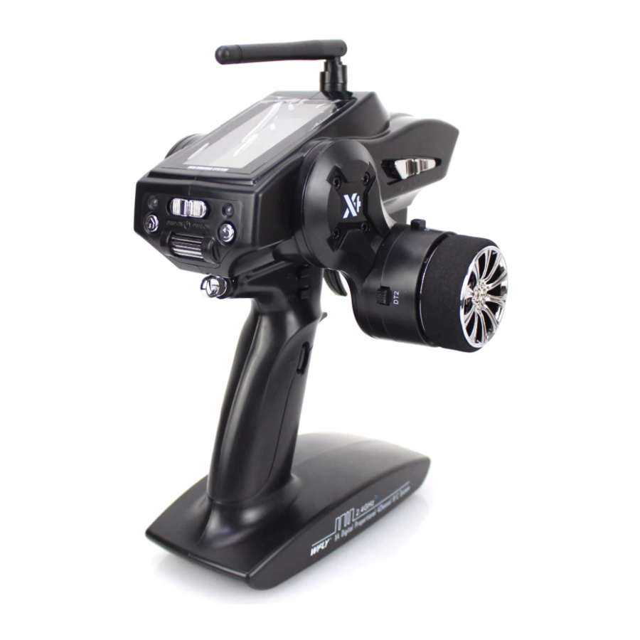
Summary of Contents for Wfly X4
- Page 1 ORIGINAL 2.4GHz 2.4GHz Instruction Manual ShenZhen WFLY Technology Development Co.,Ltd. www.wflysz.com...
- Page 3 If mixed with the counterfeit product which result in damage, the company shall not be responsible for it . Please use this book or catalogue which have recorded the products. ●Transmitter (X4) ●Receiver (WFR04H) ●Battery Box For The Transmitter ●Instruction Manual ●Foam Box...
-
Page 5: Table Of Contents
Contents Important Notes Symbol Meaning Attention Point For 2.4GHz System Attention Point For High Speed Mode Attention Point For The Driving Attention Point For The Battery Attention Point For The Saved And Wasted Battery Attention Point For Others Notice Attention Point For Servo Mode Introduction The Introduction Of Transmitter The Power Switch And RF Switch... - Page 6 Contents Product Features \ Model Memory For 40 Models \ Large Car Brake Mixing \ Anti-Lock Brake System(A.B.S) \ Throttle Acceleration \ Steering Speed \ Throttle Speed \ Timer \ Trim / Switch Function Select Function Map HOME Screen MENU Screen Function List Function Description STEER...
- Page 7 Contents Function Description ADVANCE PR MIX(Programmable Mixing) A.B.S BK MIX(Brake Mixing) 4WS MIX(4 Wheel Mixing) ESC MIX(Dual ESC Mixing) TH MODE(Throttle Mode) DIAL SW(Function Select Dial And Switch) Dial, Switch Trim Model Information Model Selection Model Copy Model Name RESET System Setting Adjustment Backlight...
-
Page 9: Important Notes
Important Notes In order to ensure the safety of yourself and others, when using this product, please pay attention to the following matters. Symbol Meaning The following symbol appears in the book, indicate the safety consideration, please pay special attention to. Ignorance of this symbol may lead to death and risk of injure . -
Page 10: Attention Point For The Driving
Important Notes Attention Point For The Driving Warning Driving is forbidden during the Rainy day, strong wind and night . The transmitter cannot operate ,control , or lost its way after dropping it into the water . No driving in the following places. •Near the crowded people . -
Page 11: Attention Point For The Battery
Important Notes Caution Please check the fail safe function is normal before driving Confirmation: 1, Turn on the transmitter first and then turn on the receiver power; 2, Set the fail safe function (39 pages); 3, Turn off the transmitter; 4, Confirm the throttle and the other channels can work in the expected position. -
Page 12: Attention Point For The Saved And Wasted Battery
Important Notes Avoid battery falling from a high place may cause strongly hit. Ni-Cd Strongly hit may cause short circuit, abnormal heat, electrolyte leakage Cause burn or chemical damage. Be sure the battery disconnected when the model does not drive. Do not plug in the socket, when the charger is not charging ! Avoid abnormal heating accident. -
Page 13: Notice
Notice Attention Point For Servo Mode Warning If you want to use the X4 high speed mode, you must meet the following conditions: Servo: digital servo, 6V. Receiver power: 6V Ni-Cd battery . Transmitter speed mode setting: high speed mode(refer to page 53). -
Page 14: Introduction
Notice Introduction The Introduction Of Transmitter Antenna Display Status indicator The power switch Return key Debugging indicator Menu key Steering wheel Roller and define key Rings Slide switch (SW.2) The trigger Button (SW.1) Battery installation 1, as shown in the picture to open the battery cover. 2, remove the used battery . -
Page 15: The Power Switch And Rf Switch
Notice When you close the battery cover, please don't nip the connected line . Caution If the cable is clamped which cause a short circuit, will be on fire, abnormal heat, cause burn or fire. The Power Switch And RF Switch DISP ON PWR ON Power on with RF off... -
Page 16: Grip Lever Operation
Notice Grip Lever Operation Sw1 default setting is the timer button. Operation modes : 1, standard: button down is active, button up is inactive; 2, switch: each press will switch the state of ON/OFF . Mechanical ATL Adjustment In accordance with the user's operation feeling, when you want to reduce / enlarge the trigger. -
Page 17: Method For Switching The Left And Right Hand
Notice Method For Switching The Left And Right Hand In order to meet different users, we design different Tools: 2.5 hexagon screwdriver ways of switch for different operation habit ! Steering Rocker Hand Replacement Methods ① Remove screws on the other side of the circle ; DISP ON PWR ON ①... - Page 18 Notice The switch of Left And Right Hand Of The Methods Steering Wheel This structure lack of the steering wheel arm The steering wheel is directly installed on body, simple and flexible! ① The step of the screw on the steering wheel ,as showed in the following picture .
- Page 19 Notice No Arm Rocker Operation Mode Change Methods ① Remove the four screws which is on steering wheel arm , unpack cable; ② Remove the four screws which is on steering wheel ; ③ Remove the steering wheel arm , connect the cable, install the corresponded screw. Adjust Steering Wheel Rocker Angle Methods ①...
-
Page 20: Transmitter Antenna And Receiver
Notice Transmitter Antenna And Receiver Antenna Caution During the operation, the antenna is not vertical to the ground, it will shorten the distance of the transmitter . During the Driving, do not hold the antenna. When Adjusting the antenna , do not exceed the rotatable range. 90°... -
Page 21: How To Link
Yellow led flashing Careful When your receiver is linking ,and there are other WFLY 2.4GHz device also linking , the receiver may not be correctly connect to your X4 In this case, even if the receiver green led on , it can be that your receiver has linked to the other WFLY 2.4GHz transmitter . -
Page 22: Installation
Note: install the receiver on the ventilative place , to avoid overheating . Ni-Cd Caution X4 must be used under the following conditions: The receiver battery voltage : 3.7~6V The high speed mode is only for : digital servo . -
Page 23: Assembly
Notice Assembly Receiver And Servo Connections Connect the receiver and servos according to the following diagram . Important Notes & Notice When Connecting and installing please follow the “ " (9~13 pages). The following is reference , for Practical use different accessories has different ways to connect. Electric Model Connection Method Battery Switch... -
Page 24: Safety Considerations
Notice Safety Considerations Warning The Receiver Antenna Do not cut or tie up the antenna. The antenna can not be tie up the other wires. Do not close to the motor or power battery (etc.)which has large current ,keep at least 1CM distance. Don’t use the metal antenna seat on the metal plate made by metal or carbon fiber or other conductive material. - Page 25 Notice Warning When installing the cooling plate, please do not contact the aluminum or carbon alloy chassis and other conductive material . Brush Motor Disturbance Countermeasures Use the brush motor please make sure to install the filter capacitor . If not installed the filter capacitor or installed wrongly , the receiver may affected by the motor , lead to the wrong operation.
-
Page 26: Initial Set-Up
Notice Initial Set-up Preparations(Transmitter) ①~④ Set The Function Of Transmitter, Please Confirm And Set The Following Items. Turn on the power, the HOME screen will show the model number currently selected, if you need to change, please use the MODEL SELECTION (see page 51). Model No. - Page 27 Notice Trims Initial Setting Steering trim (DT1) check Default setting, DT1 is the Steering trim . Stir DT1 to confirm "T1" on screen moving or not . Throttle trim (DT2) check Default setting, DT2 is the throttle trim . Stir DT2 to confirm "T2" on screen moving or not . Channel 3 (DT3) check Default setting, DT3 is the CH3 .
-
Page 28: Switch, Button Description
Notice Switch, Button Description Return Menu Power Switch Roller / Confirm Digital Trim 3 Digital Trim 1 Slide Switch Digital Trim 4 Digital Trim 2 Throttle trigger Steering Wheel Button Power switch: push Power Switch to is power off , push Power Switch to PWR ON is power on normally , push Power Switch to DISP ON is power on with RF off . -
Page 29: Product Features
Product Features •Model Memory For 40 Models Each model can be set independent name . You can simply set parameters of models that only has few difference by MODEL COPY function . •Large Car Brake Mixing Brake mixing of the front and rear wheels of 1/5GP and other large cars can be adjusted independently . -
Page 30: Function Map
Function Map HOME Screen / MENU Screen... - Page 31 Function Map...
-
Page 32: Function List
Function Map Function List Function List Function Function Description PAGE Abbreviation Servo angle adjustment function EXP(STEER) Steering curve adjustment SPEED(STEER) Steering servo delay EXP(THR) Throttle curve adjustment SPEED(THR) Throttle servo delay TH ACC Adjust the throttle neutral position Sever operation revering TRIM Selection of functions operated by digital dial and digital trim SUBTR... -
Page 33: Function Description
Function Description STEER Adjust the positive and negative travel of steering channel simply . Min is 0 , no action ; Max is 100,steering travel depends on EPA . Set: Main Menu → STEER → D/R EXP(STEER) This function is used to change the sensitivity of the steering servo around the neutral position . -
Page 34: Speed
Function Description SPEED When the fast operate steering, the body may suddenly lose control, or the danger of slip. The “SPEED(STEER)” can avoid the occurrence of the situation . Understeering Spin Smooth conrnering Without "SPEED" With "SPEED" • Adjust the steering wheel TURN and RETURN delay of servo action respectively. the fastest speed , no delay. -
Page 35: Thr
Function Description EXP(THR) This function can make the throttle accelerate and the brake more sensitive or smooth (corresponding to the ESC or throttle servo) , its adjustment does not affect the maximum travel of throttle setting. EXPF 0~-30 smoothly. linear . 0~+30 sensitivity. -
Page 36: Speed
Function Description SPEED(THR) On the wet road the sudden throttle operation will cause the wheel slip so that the model can not normally go forward. Set the throttle delay can prevent the waste of energy and allows you to enjoy a more smooth operation. -
Page 37: Th Acc
Function Description TH ACC(THR) Adjust operation amount near the throttle acceleration and brake neutral position . Near the neutral will not produce the acceleration action. Near the neutral will produce the strongest acceleration action. As the value increases, the effect will increase! Accelerator is Influenced by the travel setting. - Page 38 Function Description PRIMARY Set the positive and negative of each channel independently . Note: Please set the direction according to your model ! Set: Main Menu → PRIMARY → REV TRIM neutral Compensate the operation amount of the neutral point of throttle, steering, CH3 and CH4.
- Page 39 Function Description Implement the most flexible travel adjustment, can respectively adjust one direction travel of the throttle, steering, CH3, CH4 without influencing the other direction . The related matters of the maximum travel. Actually travel setting can determine the maximum travel of each channel, but when you adjust the following functions , it may exceed the maximum range of travel: Carburetor Control linkage SUBTR...
- Page 40 Function Description This function is to preset the CH3, CH4 at a fixed position. During the adjustment of the following functions, the action of CH3 and CH4 will be base on mixing control, instead of fixing in the preset position: PR MIX BK MIX 4WSMIX...
- Page 41 Function Description The Calculation Of The Time Total time = lap1 + lap2 + lap3 +... Exp: *When the car finish the first lap, short press the button to record time of 1'5" , the total time is 1'5"; *When the car finish the second lap, short press the button to record time of 1'15" , the total time is 2'20"...
-
Page 42: Function Description
Function Description ADVANCE PR MIX(Programmable Mixing) This function allows you to apply mixing between the steering , throttle , CH3 , CH4 . MST : Master channel ,select the channel needed to be mixed . SLV : Slave channel , select the channel to mix. The movement of the master channel side will be added to the movement of the slave channel side . -
Page 43: A.b.s
Function Description A.B.S A.B.S X:Y Duty Cycle X: Braking Y: Brake Gap Trigger point Brake returns A Cycle No configuration trigger operation direction A.B.S TG.P : trigger position . as long as the brake it will generate A.B.S action. The brake reached 50% produce A.B.S action. brake reached 100% produce A.B.S action. -
Page 44: Bk Mix(Brake Mixing)
Function Description BK MIX(Brake Mixing) This function is use when the front and rear brakes must be adjusted independently such as the scale GP car. It has 3 modes : 1, the throttle channel control rear brakes, CH3/CH4 to control the front wheel brake. 2, the throttle channel control rear brakes, CH3&CH4 to control the front wheel brake. -
Page 45: 4Ws Mix(4 Wheel Mixing)
Function Description 4WS MIX(4 Wheel Mixing) The action of the steering channel through the mixing control make the CH3 control the movement of back wheel . RATE: CH3 rate (rear side) 0: the steering channel movement is not mixed to CH3. 100: mix the steering channel action 100% to CH3. -
Page 46: Esc Mix(Dual Esc Mixing)
Function Description ESC MIX(Dual ESC Mixing) The action of throttle channel make the channel 4 to control the front wheel move by mixing . RATE : 0 , the throttle will not be mixed to CH4. 1-100 , the throttle will be mixed to CH4 1%-100% . MXMD : Mix mode on : throttle servo delay , neutral point rate , throttle curve , idle speed, neutral point brake, throttle acceleration , A.B.S , brake can be mixed to CH4. -
Page 47: Th Mode(Throttle Mode)
Function Description TH MODE(Throttle Mode) SXNT[The Midpoint Rate] Select rate of the acceleration and braking action as 7:3 or 5:5. Acceleration Brake Acceleration Brake Direction Direction Direction Direction Set: Main Menu → ADVANCE → TH MODE → SXNT IDLUP [Idle Speed] This function is used to improve engine starting performance by raising the idling speed when starting the engine of a gasoline model. - Page 48 Function Description NTBRK [Neutral brake] Execute braking action at the neutral positive of the throttle. 0 : no brake. 1-100 : 1%-100% brake. Neutral brake Application: 1,Directly set , it will take effect. 2,The switch is set to NTBRK , start or stop the function by the switch .
-
Page 49: Dial Sw(Function Select Dial And Switch)
Function Description DIAL SW(Function Select Dial And Switch) Set the function of switch and trim . Dial, Switch Switching mode (SW1): TURN : press to switch ON/OFF state. NATURE : press is ON , release is OFF . Button can be assigned to the functions below: ON/OFF TIMER ESCMIX... -
Page 50: Trim
Function Description Trim Set step and function of the trim . The step can be set to 1~20. Trim direction : NOR(normal) and REV(reverse). Trim can be assigned to the functions below: ST-TRM 4WSMIX TH-TRM BK4-RT SPEED BK3-RT ACCBK PMX-R ACCFW PMX-L CYCL... -
Page 51: Model Information
Function Description Model Information Model Selection 40 models can be stored and selected. Set: Main Menu → MODEL→ MODEL Model Copy Copy the currently selected model data to another , without changing the current model You can simply set parameters of models that only has few difference by data . -
Page 52: System Setting
Function Description System Setting Adjustment When the throttle and steering wheel appear the mechanical deviation, use ADJUSTE function to fix. Setting method: 1,When "NEUT" shows , release the trigger and wheel , then press confirm button. 2,When "ENDPOINT" shows , turn the trigger and wheel to the both side endpoints for several times ( as the following graph) , then release them , and press confirm button. -
Page 53: Battery Type Setting
Function Description Battery Type Setting Please select the correct power supply solutions! Different battery needs to select different power supply scheme. If not choose properly, it will not damage the transmitter. But it will affect the life of the battery. When you hear the continuous warning alarm , it means the voltage is too low, please replace new battery. -
Page 54: Reference
Reference Transmitter Receiver Model: X4 Model: WFR04H Application: car , boat Application : model car, boat Band: 2.400GHz-2.483GHz Band: 2.4GHz-2.483GHz Power: ≤ 100mW odulation : DSSS Modulation: DSSS Resolution: 1024 Language: Chinese, English Voltage: 3.7V-12.6V, 60mA ≤ Memory: 40 groups Size: 34.85x21x11.3... - Page 56 EN201708V0.7...
Need help?
Do you have a question about the X4 and is the answer not in the manual?
Questions and answers