Advertisement
Quick Links
Product Family:
Manual Number
Revision and Date
Change to Page 15. Address Switch
The second sentence in the Address Switch section is incorrect. There is no BCD (Binary Coded Decimal) involved with the
addressing.
Instead of "The decimal address is set in BCD (Binary Coded Decimal) format with valid addresses from 1 to 90 decimal." the
sentence should be:
"The decimal address is set from 1 to 90 decimal."
Change to Page 19. Troubleshooting
For the "DIAG off" entry in the troubleshooting table, the cause listed is "DCU is defective". Two other possible causes are a
defective CPU module or base.
Errata Sheet
Errata Sheet
This Errata Sheet contains corrections or changes
made after the publication of this manual.
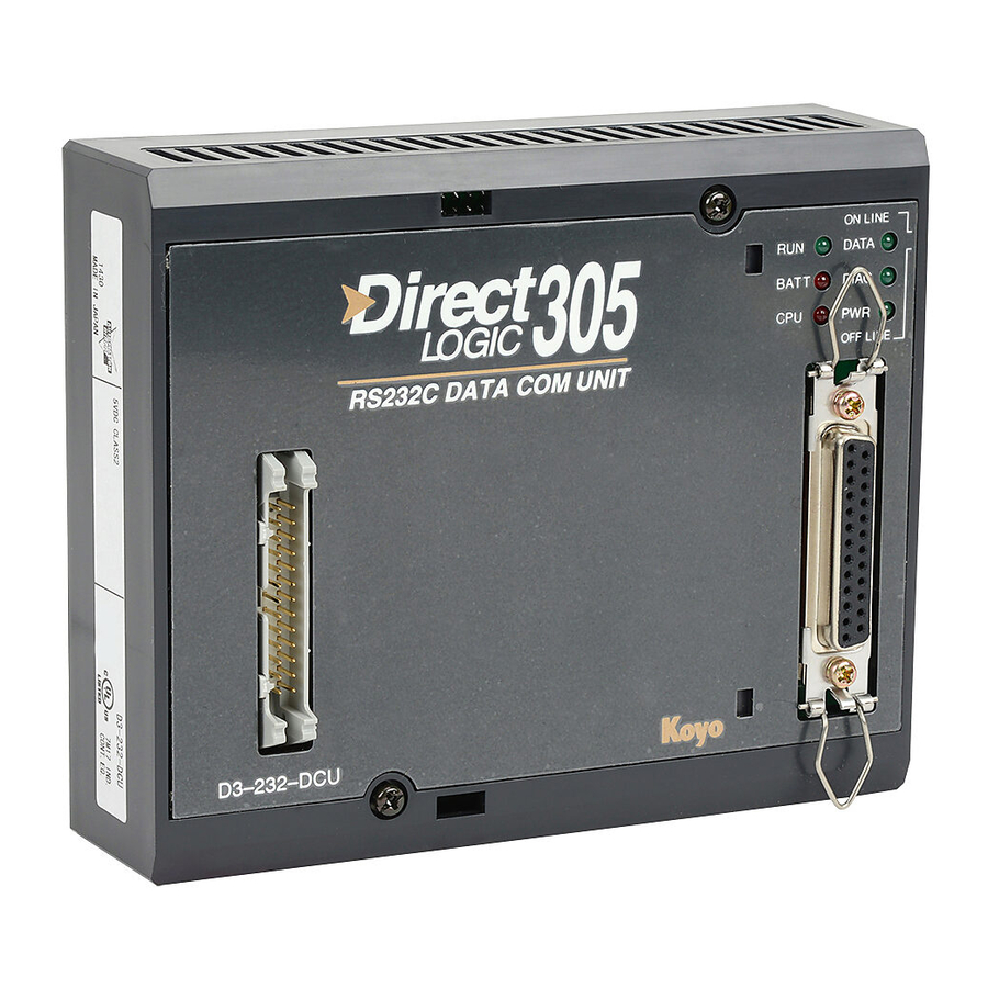
DL305
D3-DCU-M
1st Edition, Rev. A; June, 1998
Date:
Page 1 of 1
April 2018
Advertisement

Related Manuals for AutomationDirect DL305

Summary of Contents for AutomationDirect DL305
- Page 1 Errata Sheet This Errata Sheet contains corrections or changes made after the publication of this manual. Date: April 2018 Product Family: DL305 Manual Number D3-DCU-M Revision and Date 1st Edition, Rev. A; June, 1998 Change to Page 15. Address Switch The second sentence in the Address Switch section is incorrect.
- Page 2 Introduction Is this the right This manual is designed to allow you to quickly install your DL305 Data manual for you? Communications Unit (DCU). This is the only manual you will need if your are using the DCU as an interface for the Direct SOFT programming package or, as a communications port for an operator interface.
- Page 3 As a communication port, you can connect various devices, such as operator Purpose interfaces or personal computers. Communication Since the DCU does not require any programming, you can simply set the DCU Port communication parameters, connect the appropriate RS232C or RS422 cables, and start programming or transferring data. DL305 with DCU...
- Page 4 I/O information, and Register memory information. As part of a PLC Network Slave — The DCU can only be used in a DL305 PLC station that is serving as a network slave station. In this case, the DCU “listens” to the network for any messages that contain the DCU’s address.
- Page 5 How can I connect the DCU? – Four Simple Steps Complete the following steps to connect the DCU. Cable STEP 1. Build the communication cable that fits your needs. Set the Switches STEP 2. Set the DCU switches. (Baud rate, parity, etc.) Install the DCU STEP 3.
- Page 6 Step 1: Build the communication cable Things to Consider There are several considerations that help determine the type of cable needed for your DCU application. 1. Will the DCU be physically connected in a point-to-point configuration or multi-drop configuration? 2. What electrical specification is best for your application? RS232C or RS422? 3.
- Page 7 You should also use this configuration when you want to connect a Direct NET master station to a single Direct NET slave station. Use the multi-drop configuration to connect one master to two or more slaves. Point to Point DL305 with DCU DL405 Master DL305 PLC Slave...
- Page 8 Consideration 2: There is a specific model of DCU for both RS232C and RS422 communication. Your Electrical application and configuration choice will help determine which electrical Specification specification is best for you. If you are using multi-drop, you should use RS422. (You RS232C or RS422 can use RS232C/RS422 converters if necessary.) If you are using point-to-point, you may have a choice between RS232C and RS422.
- Page 9 DL405 DL305 DL405 DCM to DCU (RS232C) Master Slave DL305 DCU 2 TXD 3 RXD 7 GND 7 GND DL405 DCM DL305 Personal Computer to DCU (RS232C)
- Page 10 Multi-drop, DL405 DCM to DL305DCU and DL405 DL305 DL305 DL405 DL405PLC Slaves (RS422) CPU Port Master Slave Slave Slave 7 GND 7 GND 7 GND 7 GND +RTS +RTS +RTS +RTS –RTS –RTS –RTS –RTS +CTS +CTS +CTS +CTS DL405 –CTS...
- Page 11 Consideration 4: Although many types of cables may work for your application, we recommend you Cable use a cable that is constructed to offer a high degree of noise immunity. A cable Specifications constructed equivalent to Belden 9855 should be sufficient. The following specifications should be used as a guideline.
- Page 12 Multi-drop Termination Resistors — It is important you add termination resistors at each end of the RS422 line. This helps reduce data errors during data transmission. You should select resistors that match the cable impedance. For example, a typical 22 AWG solid conductor cable with 4.5 twists per foot has a typical impedance of about 120 .
- Page 13 Consideration 6: PLC Direct offers a Universal Cable Kit (part number FA–CABKIT). This cable kit A Quick Test Cable allows you to connect various types of Direct LOGIC products with an RS232C cable in a matter of minutes. The kit consists cable (phone cable with male plugs already attached) and several specially wired connectors.
- Page 14 Direct NET Interface The DCU can only be used as a slave station, so set the switches to match the communications parameters for the master station. Connection DL405 PLC Master - Slave Network DCM as Master DL305 DCU as Slave...
- Page 15 There are two banks of switches located on the side of the DCU that are used to set Switch Settings the communications and protocol parameters. The following diagram shows the locations and setting options. ON OFF ASCII Mode HEX Mode Not Used Not used PGM Mode at power up...
- Page 16 Online / Offline As you examined the diagrams at the Switch beginning of this manual you may have noticed you can still connect a Handheld Programmer Online even when there is a cable connected to the DCU. There’s an Online/Offline switch on the Offline side of the unit that determines which connection has control of the CPU.
- Page 17 See the DL305 User Manual for details on power budget calculations. On the back of the DCU is a switch to select if it will receive power form the base (INT –...
- Page 18 Install the DCU Use the following procedures to install the DCU. WARNING: Always disconnect the system power before installing or removing any system component. Also, do not install a DCU while the CPU is in RUN mode. This may cause unpredictable operation which can result in a risk of of electrical shock, personal injury, or equipment damage.
- Page 19 Step 4: Verify that it’s working correctly Check the DCU indicators to verify the DCU is operating correctly. The following diagram shows the proper indicator conditions. On when PLC is in On (flashing) when Run Mode data is being transmitted DATA On when PLC On when internal...
-
Page 20: Troubleshooting
Troubleshooting If the DCU does not seem to be working correctly, check the following items. 1. Cable and connections. Incorrectly wired cables and loose connectors cause the majority of problems. Verify you’ve selected the proper cable configuration and check to see the cable is wired correctly. 2. -
Page 21: Specifications
Specifications Environmental Operating Temperature ....32 to 140 F (0 to 60 C ) Specifications Storage Temperature ....–4 to 158 F (–20 to 70 C ) Operating Humidity .
Need help?
Do you have a question about the DL305 and is the answer not in the manual?
Questions and answers