ATEN VK Series User Manual
Hide thumbs
Also See for VK Series:
- User manual (385 pages) ,
- User manual (378 pages) ,
- User manual (389 pages)
Table of Contents
Advertisement
Quick Links
Advertisement
Table of Contents

Subscribe to Our Youtube Channel
Related Manuals for ATEN VK Series


Summary of Contents for ATEN VK Series
- Page 1 ATEN VanCryst™ VK Series & Configurator ATEN Control System User Manual...
-
Page 2: Compliance Statements
ATEN Control System User Manual Compliance Statements FEDERAL COMMUNICATIONS COMMISSION INTERFERENCE STATEMENT This equipment has been tested and found to comply with the limits for a Class A digital device, pursuant to Part 15 of the FCC Rules. These limits are designed to provide reasonable protection against harmful interference when the equipment is operated in a commercial environment. - Page 3 ATEN Control System User Manual Industry Canada Statement This Class A digital apparatus complies with Canadian ICES-003. RoHS This product is RoHS compliant.
-
Page 4: About This Manual
ATEN Control System User Manual About this Manual This user manual is provided to help you get the most from your ATEN Control System. It covers all aspects of installation, configuration, and operation of the ATEN controllers, configuration software, and their accessories, including:... - Page 5 Control Box and Control Pad. Chapter 2, Hardware Setup Provides the necessary steps to set up the ATEN Control System, including the detailed wiring of the different types of hardware interface connections. Chapter 3, Browser Operation Provides information about the Control Box’s and Control Pad’s web interface...
-
Page 6: Conventions
Box (VK1100 / VK1200 and VK2100 / VK2200) and ATEN Control Pad (VK0100 and VK0200). ATEN Control Box, ATEN Control Box or Control Box refers to all models of ATEN Control Box Control Box, including the VK2100 / VK2200 Control Box and the VK1100 / VK1200 Compact Control Box (Gen. -
Page 7: Package Contents
ATEN Control System User Manual Package Contents The standard package contents of each VK device are described below: VK0100 1 VK0100 8-Button Control Pad 1 button pack 6 terminal blocks 1 faceplate 1 user instructions* VK0200 ... -
Page 8: Vk2200
ATEN Control System User Manual 1 power cord 1 user instructions* VK2200 1 VK2200 Control Box Gen. 2 1 rack mount kit 30 terminal blocks 1 power cord 1 foot pad set (4 pcs) ... -
Page 9: Vk248
Note: Read this manual thoroughly and follow the installation and operation procedures carefully to prevent any damage to the VK Series devices and other connected devices. New features may have been added after the release of this manual. For an up-to-date user manual, visit: http://www.aten.com/global/en/... -
Page 10: Product Information
For information about all ATEN products and how they can help you connect without limits, visit ATEN on the Web or contact an ATEN Authorized Reseller. Visit ATEN on the Web for a list of locations and telephone numbers: International http://www.aten.com... - Page 11 ATEN Control System User Manual The manufacturer of this system is not responsible for any radio and/or TV interference caused by unauthorized modifications to this device. It is the responsibility of the user to correct such interference. The manufacturer is not responsible for any damage incurred in the operation of this system if the correct operational voltage setting was not selected prior to operation.
-
Page 12: Table Of Contents
ATEN Control Pad........ - Page 13 ATEN Touch Panel ........
- Page 14 Adding Non-KNX-Compliant Devices to ATEN Configurator ..103 Via ATEN Device Library or My Library....103 Via the Properties Column .
- Page 15 Frame & Line ........146 Object Properties for ATEN Keypad / Control Pad ....147 Button / Slider Bar / Dial Kit Actions .
- Page 16 Monitor ATEN-controller-managed Devices via Unizon™..206 Control ATEN-controller-managed Devices via Unizon™ ..206 Enabling Monitoring and Control via Unizon™ ....207 Creating a Monitor Item.
- Page 17 Button Sounds ......... . 259 The ATEN Control System App ....... 260 Demo/Start Screen .
- Page 18 Datapoint Types ......... . . 313 ATEN Control Box Reset Button....... 316 Windows OS Button Limitation .
-
Page 19: Introduction
ATEN Touch Panel. The ATEN controller works as the main controller that provides connectivity to hardware devices commonly seen in settings such asmeeting rooms, conferences, boardrooms, and classrooms. - Page 20 ATEN Control System User Manual The ATEN Control System is the perfect solution for any meeting rooms, conferences, boardrooms, classrooms, and any other room setting that requires a centralized, mobile control of a variety of hardware devices through streamlined Ethernet-based management system with optimum efficiency and...
-
Page 21: Benefits
Simplified Setup No matter how large the room or how complicated the hardware, the ATEN Control System can be deployed in 3 easy steps: connecting the hardware, configuring the system, and uploading Viewers for remote control access. -
Page 22: On-The-Go Control
ATEN Control System User Manual control by any mobile device. Various support services also provided with the solution include driver downloads, database generation, upgrade tools, etc. — to help system integrators build easy-to-control applications in a wide range of scenarios effortlessly. -
Page 23: Features
Supports native KNX IP for building management systems Telnet, TCP, UDP, ONVIF, PJLink, HTTP, and HTTPS compliant Supports project file backup Supports up to 8 ATEN Keypads Web GUI for easy system configuration 2 free licenses for mobile control* ... -
Page 24: Aten Control Pad
ATEN Control System User Manual ATEN Control Pad Supports various connection interfaces: 2 RS-232 serial ports 2 relay channels 1 digital input port 1 Ethernet port Designed to mount in 2-gang EU type and MK type junction boxes (for VK0200) ... -
Page 25: Aten Configurator
Supports ControlAssist that allows PC control (PC shutdown, media files, PowerPoint files)* Built-in Database Generator for device driver setup and overall device management. Built-in ATEN Library comprising 10,000+ device drivers and complete ATEN VanCryst product drivers Event scheduling Two-way communication enables user-defined event monitoring to automatically trigger the next actions ... -
Page 26: Control Interfaces
Natively installed with the ATEN Control System app for centralized control of control system deployments PoE-compatible Capacitive multi-touch screen Flexible mounting using any standard VESA-compliant 75 x 75 mm equipment or desk / wall mounting using the ATEN VK304 tabletop kit / VK302 wall mount kit... -
Page 27: Requirements
Prepare the following equipment and make sure your equipment meets the minimum requirements specified below. Hardware devices to be controlled by your ATEN controller Bidirectional RS-232/422/485 serial devices One-way IR or serial transmitter hardware devices (for Control Box only) ... -
Page 28: Accessories
ATEN Control System User Manual Accessories Optionally purchase ATEN accessories to enhance the functionality of your Control System. For more information, visit the ATEN website. Contact your ATEN dealer to purchase these accessories. Model Description 2XRT-0004G Full Range IR Emitter (1.8 m) -
Page 29: Hardware Setup And Panel Operation
2. Make sure that the power to all devices connected to the installation are turned off. You must unplug the power cords of any computers that have the Keyboard Power On function. ATEN Control Box Panel Components VK2100 Front View... - Page 30 ATEN Control System User Manual Component Description relay LEDs The LEDs light green to indicate an active device connection (closed loop). IR / serial LEDs The LEDs light green to indicate an active device connection or IR / serial signals being transmitted.
- Page 31 Chapter 2. Hardware Setup and Panel Oper- Component Description controller ID Used to set an ID for the Control Box. switch...
-
Page 32: Vk2100 Rear View
ATEN Control System User Manual VK2100 Rear View VK1100 Rear View Component Description grounding terminal Connects to the grounding wire. power socket Plugs in the power cord from an AC power source. power switch Powers the unit on or off. -
Page 33: Vk2200 Front View
Chapter 2. Hardware Setup and Panel Oper- Component Description RS-232/422/485 4 / 2 ports supporting RS-232/422/485 conversion by serial ports pin assignment and RTS/CTS flow control. The RS- 232, RS-422, or RS-485 connection is defined by pin. For pin assignments, see page 39. Ethernet port Connects the unit to a network. - Page 34 ATEN Control System User Manual Component Description relay LEDs Lights green to indicate an active device connection or signals being transmitted. I/O LEDs Blinks green once to indicate system startup, with the IR / serial LEDs buzzer beeping once...
-
Page 35: Vk2200 Rear View
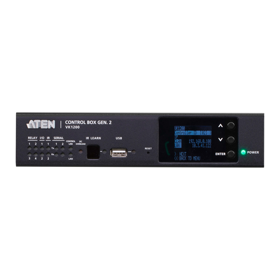
Chapter 2. Hardware Setup and Panel Oper- Component Description LCD panel and Use the Up, Down, and Enter buttons to display the unit’s system information, and set its controller ID. buttons power LED Lights green when the unit is turned on. VK2200 Rear View VK1200 Rear View Component... - Page 36 Connects the unit to a secure subnetwork, separate from the corporate LAN, for managing IP devices and configuration by the ATEN Configurator VK6000, as well as for remote control by ATEN Keypads, Touch Panel or the ATEN Control System app on mobile devices.
-
Page 37: Rack Mounting The Aten Control Box
Chapter 2. Hardware Setup and Panel Oper- Rack Mounting the ATEN Control Box VK2100 / VK2200 1. The VK2100 / VK2200 can be mounted onto a 19” (1U) system rack. The following diagrams are exemplified using VK2100.Using the rack mount kit, attach the 2 mounting brackets onto the sides of the unit with the 6 screws included. -
Page 38: Vk1100
ATEN Control System User Manual VK1100 Optionally purchase an ATEN Rack Mount Kit (2X-031G) to install VK1100 onto a 19” (1U) system rack. 1. Remove the 2 screws from the bottom and 1 screw from each side of the unit. -
Page 39: Vk1200
Chapter 2. Hardware Setup and Panel Oper- VK1200 Optionally purchase an ATEN Rack Mount Kit to install VK1200 onto a a 19” (1U) system rack. Users can select the 2X-049G or 2X-021G rack mount kit for single or dual rack mount, respectively. - Page 40 ATEN Control System User Manual Double Rack Mount 1. Remove 2 screws at the bottom and 1 screw at the side from each of the two VK1200 units, as shown below. 2. Use 4 of the screws from step 2 to secure the two VK1200 units together with the link bracket.
-
Page 41: Control Box Connections
Chapter 2. Hardware Setup and Panel Oper- Control Box Connections Installation of the Control Box is a matter of connecting the appropriate wires. To set up each device, refer to the installation diagrams on the pages that follows (each step provides a corresponding page with diagram for the VK2100 / VK2200 and VK1100 / VK1200), and do the following: 1. - Page 42 ATEN Control System User Manual Note: 1. For KNX-compliant devices, connect the devices to a KNX IP interface, and then connect the KNX IP interface to the network where the Control Box is installed. 2. To check if the KNX functions are supported by the Control Box, see Specifications, page 282.
- Page 43 Chapter 2. Hardware Setup and Panel Oper- VK2100 Installation Diagram...
- Page 44 ATEN Control System User Manual VK2200 Installation Diagram...
- Page 45 Chapter 2. Hardware Setup and Panel Oper- VK1100 Installation Diagram...
- Page 46 ATEN Control System User Manual VK1200 Installation Diagram...
-
Page 47: 12 V Dc Power Output
Chapter 2. Hardware Setup and Panel Oper- 12 V DC Power Output ATEN Control Box offers the following 12 V DC outputs for providing power to hardware devices: VK1100 / VK1200 VK2100 / VK2200 Number of Channels Max. Power Supply... - Page 48 ATEN Control System User Manual Relay Power Supply 12 V DC Output Ports Power Supply: 12 V DC, 1 A / 2 A Max Connects to Switch, Screen, Projector Lift, Lighting, Motorized Equipment, Motion Device, etc. Provides 12 V DC power...
- Page 49 Chapter 2. Hardware Setup and Panel Oper- Digital Output Power Supply (inapplicable to VK1100) 12 V DC Output Ports Power Supply: 12 V DC, 1 A / 2 A Max Provides 12 V DC power for the digital output loop. Connects to Switch, Screen, Projector Lift, Lighting and Equipment Control.
- Page 50 ATEN Control System User Manual Digital Output Dual Power Supply (VK2100 / VK2200 only) 12 V DC Output Ports Power Supply: 12 V DC, 1 A / 2 A Max Provides 12 V DC power for the digital output loop.
-
Page 51: Relay
Chapter 2. Hardware Setup and Panel Oper- Relay ATEN Control Box provides the following isolated relays: VK1100 / VK1200 / VK2200 VK2100 Number of Channels Contact Rating 24 V DC, 2 A Default Status Normally Open Relay Channels NO, Isolated Relays:... -
Page 52: Ir / Serial
ATEN Control System User Manual IR / Serial ATEN Control Box provides the following IR / serial (RS-232) ports: VK1100 / VK2100 VK2200 VK1200 2-Pin IR/Serial Carrier Frequency 10 ~ 455 kHz Default Level Baud rate 300 ~ 115200 (default: 9600) -
Page 53: One Ir Transmitter
Chapter 2. Hardware Setup and Panel Oper- Serial Connection: Connect a serial device's receiver (RX) and ground terminals to a set of serial (TX) and ground terminals of the Control Box. Then configure the same serial port settings on both the Control Box and the connecting serial device, allowing them to communicate. -
Page 54: Digital I/O
Digital Input (VDC Mode): Connects to DC devices (temperature, current and monitor sensors) for providing voltage signals (1 ! 24 V) to the ATEN Control Box, to trigger certain events and/or functions when the voltage signals are above or below... - Page 55 Chapter 2. Hardware Setup and Panel Oper- Programmable Digital Output Channels Digital Output: 250 mA sink from 12 V DC Connects to Digital Output: Switch, Screen, Projector Lift, Lighting and Equipment Control. Relay Module Digital Output: Provides non-powered dry contact (open and closed) circuit control of hardware devices, such as electric screens, projector lifts and other motorized equipment, which must be connected using a relay module, as shown below.
-
Page 56: 3-Pin)
Projector, Matrix Switch, Camera, etc. Connect to devices for controlling and receiving status messages from them. For bidirectional RS-232 control, the transmit (TX), receive (RX) and ground (GND) terminals must be wired on both the ATEN Control System and the device connecting... - Page 57 3: TX+ pin 7: RTS pin 4: TX- pin 8: CTS pin 5: GND RS-232 / 422 / 485 (5-Pin) The ATEN Control System provides the following RS-232/422/485 ports: VK1200 VK2200 Number of Channels Baud rate 300 ~ 115200 (default: 9600)
- Page 58 ATEN Control System User Manual VK1200 VK2200 Stop bit 1 (default), 2 Parity None (default), Even, Odd Bidirectional RS-232 / 422 / 485 Ports Configurable by pin assignment Connects to Projector, Matrix Switch, Camera, etc. Connect to devices, configurable by pin assignments, for controlling and...
-
Page 59: Ethernet / Control Lan
The Ethernet / Control LAN port provides an Ethernet connection for controlling up to 25 (VK1100 / VK2100) or 64 (VK1200 / VK2200) LAN devices and/or remote control by ATEN Keypads, Touch Panel, and the ATEN Control System app on a mobile device in a network . -
Page 60: Aten Control Pad
ATEN Control System User Manual ATEN Control Pad Panel Components VK0100 Front View Rear View Side View VK0200 Front View Side View Rear View... - Page 61 Chapter 2. Hardware Setup and Panel Oper- Component Description buttons and button Indicate the status of the Control Pad and if the function on each button, e.g. lighting or projector, is on or off. For LEDs detailed information about device/function status under different LED activities, see LED Indications, page 44.
-
Page 62: Led Indications
ATEN Control System User Manual LED Indications Refer to the table below for the status descriptions of a Control Pad indicated by button LEDs. Button LED Status LED Activity Control Pad Status a button LED lights orange The Control Pad is powered on and the button is currently off. -
Page 63: Installing The Control Pads
Chapter 2. Hardware Setup and Panel Oper- Installing the Control Pads Installation Steps Follow the steps below to safely install the Control Pad. VK0100 RS-232 Projector Video Switch Relay Dry Contact Device Lighting Control Door Sensor Screen PoE Switch Projector Projector Lift Conference... - Page 64 For details, see RS-232 Serial Connection, page 50, Relay Connections, page 51, Digital Input Device, page 52 respectively. Note: To expand connection ports on the Control Pad, install ATEN Expansion Boxes. 3. To use PoE, connect the Control Pad to a PoE switch via an Ethernet cable.
- Page 65 In which case, the 17th controller and the ones added after that will each be sharing its ID with another controller. If you have any ATEN Expansion Box and/or Keypad connected to controllers using shared IDs, reconfigure the connection mode. For details, see Controller Properties, page 106.
- Page 66 ATEN Control System User Manual 8. Mount the Control Pad to the wall. a) Secure the Control Pad to the wall with self-prepared screws. b) Install the supplied faceplate to the Control Pad. VK0100 VK0200 (EU)
- Page 67 Chapter 2. Hardware Setup and Panel Oper- VK0200 (MK)
-
Page 68: Rs-232 Serial Connection
ATEN Control System User Manual RS-232 Serial Connection The two bidirectional RS-232 ports on the Control Pad provide serial control of hardware devices (projectors, matrix switches, etc.) and receive status messages from the connected devices. For bidirectional RS-232 control, the transmit, receive, and ground pins must be wired on both the Control Pad and hardware device. -
Page 69: Relay Connections
Chapter 2. Hardware Setup and Panel Oper- Relay Connections These 2 relay channels provide connections to control hardware devices such as electric screens, projector lifts and other motorized equipment. Each relay is normally open by default. 2 x Relay Channels Normally Open, Isolated Relays Contact Rating: 24VDC 1A Max Normally... -
Page 70: Digital Input Device
ATEN Control System User Manual Digital Input Device The digital input port on the Control Pad can be used to install a digital input device such as a switch or a sensor. The digital input channel can be configured to the VDC mode or the Dry Contact mode. -
Page 71: Ethernet
Chapter 2. Hardware Setup and Panel Oper- Ethernet The RJ-45 port provides an Ethernet connection for GUI access (page 71) and the ability to add up to 8 LAN devices per Control Pad, as shown below. The RJ-45 port is used to connect and access TCP, UDP, PJLink, ONVIF, HTTP, HTTPS, and Telnet Ethernet... -
Page 72: Aten Expansion Box
ATEN Expansion Box ATEN Expansion Boxes (sold separately) provide additional ports for a flexible expansion of the ATEN Control System. This allows you to add and control additional devices in an environment when more devices are required. With the advantage of an Ethernet-based connection, the expansion boxes are easily connected to the ATEN controller via a LAN connection from a variety of locations across a network. -
Page 73: Control Interface Devices
Chapter 2. Hardware Setup and Panel Oper- Control Interface Devices ATEN Keypad The ATEN Keypad mounts to a wall to provide control of hardware through a Control Box. The setup of the Keypad to the Control System can be illustrated as follows:... -
Page 74: Component
ATEN Control System User Manual Component The VK108US and VK112EU Keypads share the same hardware layout. For demonstration purpose, VK112EU is used as an example below. 68.51 mm 28 mm Component Description buttons VK108US The Keypad can be customized up to 14 different layouts using 4 to 8 buttons. -
Page 75: Led Indications
Chapter 2. Hardware Setup and Panel Oper- Component Description LAN port Connects the Keypad to LAN Supplies power (PoE) if a power sourcing equipment is installed. LED Indications Refer to the table below for the status descriptions of a Keypad indicated by button LEDs. -
Page 76: Layout Examples
ATEN Control System User Manual Layout Examples VK108US VK112EU... -
Page 77: Installing Aten Keypad
Chapter 2. Hardware Setup and Panel Oper- Installing ATEN Keypad You can install the Keypad in a wall, podium, or desk. To install the Keypad, follow the steps below: 1. Choose a location free of interference and prepare the installation site. You can install the Keypad to a wall box or directly into the chosen surface. - Page 78 2. Pair the Keypad with a Control Box by adjusting the Keypad ID Switch (blue) to the ID number that the Control Box uses. Note: One ATEN Control Box can work with up to 8 Keypads. 3. Supply the Keypad with power and network connectivity using one of the following methods.
- Page 79 Chapter 2. Hardware Setup and Panel Oper- a) Cut the connector end of the power adapter cable. b) Strip 0.5 cm off the insulation cover of the power adapter cable to expose the two wires, the +5V wire, and the grounding wire. To determine wire polarity, use a voltmeter.
- Page 80 ATEN Control System User Manual From the top row, attach each row of button caps to the Keypad by pressing on the hinges. Caution: When removing button caps, place your fingers on the top of button caps and then press downwards, as illustrated below.
-
Page 81: Aten Touch Panel
Chapter 2. Hardware Setup and Panel Oper- ATEN Touch Panel Panel Overview Front View Top View Rear View Bottom View Component Description touch screen Tap on the screen to operate the control system and/or configure the touch panel. status LED Lights on when the touch panel is powered on. -
Page 82: Mounting The Touch Panel
VESA compliant (75 x 75 mm). For more information about the mounting accessories, please visit the product web page. Desk Mount To mount the VK330 on a desk using ATEN desk mount accessory — VK304 — refer to the diagram below. - Page 83 Chapter 2. Hardware Setup and Panel Oper- Wall Mount To mount the VK330 onto a wall using ATEN wall mount accessory — VK302 — follow the steps and refer to the diagrams below. 1. Secure the wall plate to the wall using the wall anchors and screws.
-
Page 84: Installing The Touch Panel
2. Put the power switch to ON. The Touch Panel starts loading and displays the Start page. Operating the Touch Panel For details on using the Control System app, see The ATEN Control System App, page 260. To configure system settings of the Touch Panel, press the Function button on the device open the system settings page. -
Page 85: Configuring The Network Settings
2. Tap Network & Internet > Ethernet > Ethernet IP Mode to configure the settings. Updating Control System App To update the Control System app on your ATEN Touch Panel, follow the steps below. 1. Download the Control System app from the product web page and save the file to a USB drive. - Page 86 ATEN Control System User Manual This Page Intentionally Left Blank...
-
Page 87: Web-Based Configuration And Control
Control Overview The ATEN controller can be configured over a standard TCP/IP connection via its built-in Graphical User Interface (GUI). Because it can be accessed from anywhere over a network or the Internet, operators can easily log in via a web browser. -
Page 88: Lcd Panel
IP Installer Using a Windows PC, download the IP Installer zip file in Support and Downloads from the ATEN controller’s product web page. Then extract and execute IPInstaller.exe. A window similar to the one below appears. Make sure the proper network adapter is selected and click Enumerate to... -
Page 89: Logging In
Chapter 3. Web-Based Configuration and Logging In To access the GUI, type the IP address of the controller into the address bar of any browser. If a Security Alert dialog box appears, accept the certificate — it can be trusted. The Welcome screen appears: ... -
Page 90: Dashboard
ATEN Control System User Manual Dashboard The Dashboard appears when you successfully log in to the Control Box. The Dashboard gives a quick view of each setting and provides a link to each page. Click Edit to configure the settings. -
Page 91: Settings
Chapter 3. Web-Based Configuration and Settings The Settings view contains tabs consisting of different configurations of the controller. The page is divided into two parts: Interactive Display Panel: configures the options Top Bar: provides icons to exit the settings page and log out of the web session. - Page 92 ATEN Control System User Manual Setting Descriptions Date & Time Automatically Time Zone: Select a time zone for the controller. Choose the city that most closely corresponds to where it is located. NTP Server Settings Assign an NTP server for the controller to synchronizes its clock.
-
Page 93: Licenses For Mobile Control
Chapter 3. Web-Based Configuration and Licenses for Mobile Control A license is a software permit that an ATEN controller grants to a mobile device for remote control. If you have three licenses for a controller, you can have three mobile devices remotely operate the controller at the same time. -
Page 94: Storage
ATEN Control System User Manual Setting Description Remove When a device is accessing the controller, you can click the Remove button to disconnect the session. Storage The Storage tab displays information about the space available for storing Viewers on the controller. -
Page 95: Access
Chapter 3. Web-Based Configuration and Access The Access tab allows you to configure the access key (password) of the ATEN controller’s web interface and to set a validity period for accessing the ATEN Control System using an activation key. Setting... - Page 96 The activation key is a string of letters and numbers used to assign a validity period of accessing the ATEN Control System. To set up a validity period for accessing the ATEN Control System: 1. Select Your access to ATEN Control System will expire in and type the number of days.
-
Page 97: Monitor
Monitor The Monitor tab allows you to view and enable the monitors that have been configured for Flags and digital input devices in ATEN Configurator. Check the Show on dashboard box to show the Monitor settings on the Dashboard. Click the slide bar next to the monitor you want to enable or use the drop-down menu to select All On or All Off. -
Page 98: Network
Select Manually to set a static IP Address, Subnet Mask, and Default Gateway, or Use DHCP to have the server assign an IP address to the controller. Note: Make sure to set the ATEN controller’s IP address and Default Gateway to the same subnet. Working as a DHCP Server... -
Page 99: Connections
Chapter 3. Web-Based Configuration and Connections The Connections tab allows you to view the connection statuses and IP addresses of licensed devices, ATEN Keypads, and ATEN Expansion Boxes. -
Page 100: Schedule
ATEN Control System User Manual Schedule The Schedule tab lists scheduled events predefined using the ATEN Configurator. You can use this tab to do the following: Enable or disable scheduled events. Enable or disable scheduled days For details on setting up scheduled events, see Scheduled Events, page 199. -
Page 101: Security
SSL certificate from a trusted certifying authority and click Upload to apply the certificate. TLS Support: Each ATEN controller supports TLS 1.0, 1.1, and 1.2to allow communications with devices supporting different versions of the TLS. If you have any security concerns, disable the Enable TLS 1.0 and TLS 1.1 setting to only allow communications among devices that support... - Page 102 ATEN Control System User Manual This Page Intentionally Left Blank...
-
Page 103: Aten Configurator (Vk6000)
Chapter 4. ATEN Configurator (VK6000) Chapter 4 ATEN Configurator (VK6000) Overview The ATEN Configurator (VK6000) is a GUI-based management tool that helps you set up and configure the connected hardware and create control interfaces to be used by mobile devices and ATEN Keypads. Installation To install the ATEN Configurator software, do the following: 1. - Page 104 ATEN Control System User Manual 3. Click Next. This screen appears. 4. If you agree with the License Agreement, select I accept the terms of the license agreement, and click Next. Click Print to print the Software End User License Agreement. This screen appears.
- Page 105 Chapter 4. ATEN Configurator (VK6000) 5. To change the destination location, click Change. Click Next to proceed using the default location. This screen appears. 6. Click Install. When the process is complete, a confirmation message appears. 7. Click Finish.
-
Page 106: Getting Started Tasks
ATEN Control System User Manual Getting Started Tasks After you have installed and launched the ATEN Configurator, the main screen (page 90) appears. You will be guided to create and configure a project using the 4 tabs in the Configurator’s interface, as illustrated below. - Page 107 Chapter 4. ATEN Configurator (VK6000) Click Design or the Viewer tab to proceed. 3. In the Design tab, do the following. Create and configure a control interface (Viewer). For more information, see Configuring Control Interfaces, page 117. (Optional) Set up scheduled events to automatically carry out specified actions.
-
Page 108: Main Screen
ATEN Control System User Manual Main Screen Overview Double-click the Configurator.exe shortcut to open the ATEN Configurator software. The Project page appears: Control Description Menu Bar The menu bar contains a group of the Configurator ‘s main Menu Bar functions by category. For details, see , page 91. -
Page 109: Menu Bar
Chapter 4. ATEN Configurator (VK6000) Control Description Simulator The Simulator button is used to test the Viewer after it is created in Design. The simulator allows you to tryout the interface as it would work on a mobile device but without actually controlling devices. - Page 110 Interface Check a box to enable the feature described below: Show Welcome Page: displays the Welcome screen when the ATEN Con- figurator software opens. Auto Page Creation: automatically creates a Viewer page in Create Viewer & Design, for every hardware device that is configured in Select Device &...
- Page 111 Chapter 4. ATEN Configurator (VK6000) Menu Sub-Menu Description View These options are available from Create Viewer & Design Edit Viewer. Zoom Zooms the Viewer page to 25%, 50%, 75%, 100%, 200% or Fit in Window. Note: A mouse wheel can be used to zoom the Viewer page in or out.
- Page 112 ATEN Control System User Manual Menu Sub-Menu Description Object PowerPoint Control Template Adds a PowerPoint Control template to the Viewer. This control template is used to control PowerPoint files saved in a target computer. Media Control Template Adds a Media Control template to the Viewer.
- Page 113 Chapter 4. ATEN Configurator (VK6000) Menu Sub-Menu Description Object Align Left Aligns two or more selected objects to the Left side of the object that is selected last. Center Aligns two or more selected objects to the horizontal position of the object that is selected last.
- Page 114 Opens the ATEN Database Generator which is used to manually add and configure hardware devices. This is where you can create custom devices to add to My Device Library. See ATEN Database Generator, page 219, for details. Simulator The Simulator is used to test a Viewer’s interface after it has been created in Design.
-
Page 115: Creating Projects
ID Switch on the rear of the Control Box using the ID displayed here so that the project file will be uploaded to the controller set with the same ID. ATEN Controller Type Select the controller model you are installing. - Page 116 ATEN Control System User Manual Control Description Number of Rooms Enter the number of rooms each controller will control. Each hardware device you add will be associated with a room. When buttons are configured in the Design tab, you can select a Room under Button Action to filter the Device list so that only hardware in that room appears.
-
Page 117: Configuring Managed Devices
For details, see Left Sidebar, page 100. Left Sidebar The left sidebar provides a tree view of the ATEN Control System deployment in each project. Use the sidebar to add/remove a controller, Expansion Box, or Room. -
Page 118: Left Sidebar
Rename the room. Use the buttons at the bottom of the sidebar to Add Room. Expansion Box ATEN Expansion Boxes connect over a network to add ports to the controller via its Ethernet port. Clicking Add Controller or Expander opens a window which allows you... -
Page 119: Device Configuration List
Device Configuration List The Device Configuration page lists the controller ports by type. Click a port to view its Properties. Double-click a port to open the ATEN Device Library and search for the hardware device to configure the port. Configure each port according to the hardware device connected to it. - Page 120 ATEN Control System User Manual Control Description Unizon™ Select this option to allow Unizon™ to manage and monitor the corresponding device. Note: Configuration will also be required on Unizon™ for this feature to work. For an overview of how to set up the function, see Centralized Monitoring and Control via Unizon™, page 206.
-
Page 121: Adding Devices To The Device Configuration List
2. Click library. In the pop-up window, click the drop-down list to select ATEN Device Library or My Device Library, and then double-click an item to add the device. The selected device is added to Device Configuration. -
Page 122: Via The Properties Column
(a) Click the arrow button and select Add device from the Library to open the Library. (b) Click the drop-down list to select ATEN Device Library or My Device Library, and then double-click an item to add the device. ... -
Page 123: Adding Knx-Compliant Devices To Aten Configurator
If the device is not in the Library, create the device using Database Generator. For details, see Editing / Adding a New Device, page 226. Adding KNX-compliant Devices to ATEN Configurator 1. Click File and then Import ETS Project. The configurations for your KNX devices appear in the Controller tab on the left-side bar. -
Page 124: Device Properties
Controller ID Switch. Identify ATEN Expansion Box and Keypad by IP Address Enable this function for the controller to connect to ATEN Expansion Box or Keypad by identifying their IP addresses. Use this function if any of the following scenarios applies: ... - Page 125 Expansion Boxes and/or Keypads. In the Devices tab, enable the Identify ATEN Expansion Boxes and Keypads by IP address function the Properties panel. For example, if you have 17 controllers set up under the same subnet, with controller 1 and 17 using ID01, enable the function for both of these controllers.
-
Page 126: Expansion Box (Expander)
Expander ID: Select the expander ID. Make sure the ID matches the one set physically on the Expansion Box. IP Address: Only specify the IP address of the expansion box when the Identify ATEN Expansion Box and Keypad by IP Address setting is enabled. -
Page 127: Serial Device Properties
Chapter 4. ATEN Configurator (VK6000) Serial Device Properties Click a serial device from the Device Configuration list to configure its properties. Name: Displays the device model. Add Device: Use this button to add devices. For details, see Adding Non- KNX-Compliant Devices to ATEN Configurator, page 103. - Page 128 ATEN Control System User Manual between parts of a feedback message. The controller uses this value to identify the end of a message. Keep Connection Alive: The controller sends a command to the serial device to maintain the connection and avoid timeout issues.
-
Page 129: I/O Device Properties
Chapter 4. ATEN Configurator (VK6000) I/O Device Properties Click an I/O device from the Device Configuration list and select Input (VDC), Input (Dry Contact), or Output to configure its properties. Name: Displays the device model. Add Device: Use this button to add devices. -
Page 130: Ir/Relay Device Properties
ATEN Control System User Manual IR/Relay Device Properties Click an IR/Relay device from the Device Configuration list to configure its properties. Name: Displays the device model. Add Device: Use this button to add devices. For details, see Adding Non- KNX-Compliant Devices to ATEN Configurator, page 103.Category:... -
Page 131: Ethernet Device Properties
Protocol Type: Click to select the protocol for the Ethernet device. The ATEN Control System supports control of devices via telnet, ONVIF, TCP, UDP, HTTP, and HTTPS. IP Address: Type to assign a fixed IP address to the Ethernet device. - Page 132 VE Manager Password: Type the administrator password of the VE Manager to allow the controller to access video sources connected to the video extenders managed by the VE Manager. Note: This setting is only applicable to ATEN networked video extenders. ...
-
Page 133: Library
Chapter 4. ATEN Configurator (VK6000) Library The Project Bar provides the Library option. Use the Device Library tab (shown below) to configure controller ports according to the connected hardware devices. The Device Library provides an extensive database of hardware devices that can be double-clicked or drag and dropped into the Device Configuration page to configure controller ports. -
Page 134: Device Library
For devices not in the library, use the ATEN Database Generator to create custom hardware (see page 219). Click Library on the Project bar or double-click a port on the Device Configuration page to open the ATEN Device Library. -
Page 135: Configuring Control Interfaces
Chapter 4. ATEN Configurator (VK6000) Configuring Control Interfaces Overview To configure the control interfaces,i.e. Viewers for your mobile devices, Keypads, Control Pads, or Touch Panel, click the Design tab in Configurator. Element Description Left Sidebar Use the left sidebar to configure the following ... - Page 136 ATEN Control System User Manual Element Description Simulator The Simulator button is used to test a Viewer’s interface after it has been created. The simulator allows you to tryout the interface as it would work on a mobile device but without actually controlling devices.
-
Page 137: Left Sidebar
Chapter 4. ATEN Configurator (VK6000) Left Sidebar Viewer The Left Sidebar provides a tree view of the Viewers and Pages. Clicking a Viewer opens the Page Overview which is a layout of the Viewer. Right-click a Viewer to Delete, Rename or Edit the Viewer. -
Page 138: Adding A Viewer
ATEN Control System User Manual Adding a Viewer A Viewer is a control interface that you use on mobile devices, ATEN Keypads, ATEN Control Pads, or ATEN Touch Panels to centrally control devices and equipment. To add a Viewer and/or its associated control pages, follow the steps below. - Page 139 Chapter 4. ATEN Configurator (VK6000) 2. Select the device for which the Viewer will be created. 3. Configure the settings for your selected device. Mobile Device Setting Description Type Use this drop-down menu to select the mobile device that will be used to control hardware devices in a room.
- Page 140 Select a template for the Viewer’s home page. Blank: Creates a custom home page that you design from scratch. ATEN Themes: Select any of the ATEN Themes to create a home page and other device pages with graphics. These pages are customizable. Keypad Setting...
- Page 141 Blank: Creates a custom home page that you design from scratch. ATEN Themes: Select any of the ATEN Themes to create a home page and other device pages with graphics. These pages are customizable. 4. Click Done to save the configuration. An overview appears showing all...
- Page 142 ATEN Control System User Manual 5. (Optional) Add, edit, or remove the pages or adjust the basic settings of the Viewer. Control Description Click to duplicate the Viewer along with the pages. Click to edit the basic Viewer settings that you configured in step Click to add a new page to the highlighted Viewer in the left sidebar.
-
Page 143: Configuring The Viewer
Chapter 4. ATEN Configurator (VK6000) Configuring the Viewer After you have added the Viewer and the associated pages, you are ready to configure the page layout and object actions, for example, button actions in the Viewer. To configure a Viewer, follow the steps below. - Page 144 ATEN Control System User Manual 3. Click the element in the preview panel to customize the settings. See the table below for more information. Element Tasks Preview panel Shows a preview of the selected page. You can also do the following on the preview panel: ...
- Page 145 For detailed information about object properties, refer to the following sections: Object Properties for Mobile Devices and Touch Panels, page 128 Object Properties for ATEN Keypad / Control Pad, page 147 Use Library to customize the appearance of the page Library and its buttons.
-
Page 146: Object Properties For Mobile Devices And Touch Panels
ATEN Control System User Manual Object Properties for Mobile Devices and Touch Panels After you have added a Viewer (page 120) for your mobile device/touch panels, you can start configuring the pages that the Viewer contains by adding control elements. -
Page 147: Buttons
Chapter 4. ATEN Configurator (VK6000) Buttons The Button properties provide options to configure the appearance of a button, and the confirmation message and progress message before carrying out the associated action. - Page 148 ATEN Control System User Manual Alignment – Aligns a group of objects. Select multiple objects for the buttons to become available: Mode Use this drop-down menu to select one of the following button types. Normal – This is a button that stays the same when pressed.
- Page 149 To create variables, see Variables, page 200. Restrict access to this button on ATEN Control System App with a password: Limit the use of the selected button by requesting a password when the button is tapped in the Viewer. To enable this function, click this option and type the password in the box below.
- Page 150 ATEN Control System User Manual Action – Select a button action (Toggle On or Toggle Off) to display the confirmation message. Content drop-down list – Select one of the following for customization. Background – Customize the wording for the confirmation message.
-
Page 151: Groups
Chapter 4. ATEN Configurator (VK6000) Groups You can unify the properties of two or more control components (buttons, slider bars, etc.) at the same time. Depending on the elements that your group of components have, different properties will be open for configuration.Use your mouse to drag and select the components from a page, the properties that are open for configuration appear in the Properties column. -
Page 152: Labels
ATEN Control System User Manual Labels The Label properties provide settings for the displayed text and its format. Alignment – Aligns a group of objects. Select multiple objects for the buttons to become available: Name – enter the text you want to use for the label or slow double-click the label on the Edit page. -
Page 153: Slider Bars
Chapter 4. ATEN Configurator (VK6000) Slider Bars Right click on a Viewer page and select Slider Bar to add a bar. A Slider Bar can control a device, link to another page, or run a macro. - Page 154 ATEN Control System User Manual Use the Mode drop-down menu to select the type of slider bar (Basic Slider Bar or Advanced Slider Bar). Basic Slider Bar A slider bar where you enter the minimum and maximum values to calculate the range and levels on a slider bar, and then add one command to configure the Basic Slider Bar’s action (See Slider Value, page 156).
-
Page 155: Powerpoint Control And Media Control Templates
Chapter 4. ATEN Configurator (VK6000) PowerPoint Control and Media Control Templates Click a PowerPoint control template or a media control template to configure its position, size, and the PC that controls it. Position and Size – X and Y position the label at the coordinates entered. -
Page 156: Images
ATEN Control System User Manual Images The Properties for an image provide options to change and import images to the page. Images can be layered with other objects so that they can be placed as a background or as highlights for buttons (see Layering Images, page 139). -
Page 157: Layering Images
Chapter 4. ATEN Configurator (VK6000) Layering Images Images can be layered with other objects, such as labels and buttons, so that they can be placed as a background or as highlight for the page and/or other objects. -
Page 158: Videos
ATEN Control System User Manual Videos A video template is a control object used for previewing videos and assigning video sources for the managed displays. - Page 159 (on a display object), and to switch video sources by tapping or dragging and dropping actions from the Viewer. Note that video control window is only applicable to ATEN networked video extenders. For example, the following Viewer contains 8 video control objects, the top 3 are video source objects, each show a preview of its connected video source, and the bottom 5 are display objects, each showing its assigned video source.
- Page 160 ATEN Control System User Manual To set up a video control object, follow the steps below. 1. In Configurator, make sure you have added at least one video transmitter as Ethernet device to the Device Configuration list. Important: A networked video transmitter allows you to connect to other extenders in the deployment as long as they are installed under the same LAN.
- Page 161 Chapter 4. ATEN Configurator (VK6000) 5. Click the added object and configure the action. For example: (a) Create a variable to store the video source on a source object. (b) Add the switching action on a display object. For more information about creating actions, see Button / Slider Bar / Dial Kit Actions, page 150.
-
Page 162: Dial Kit
ATEN Control System User Manual Dial Kit A dial kit template consists of a display screen and a set of dial keys. To configure their appearance, click on the display area or a key. Display Screen Dial Keys Properties for Dial Key... - Page 163 Chapter 4. ATEN Configurator (VK6000) Font – use the drop-down menu to select the font for the typed text. Color – use the drop-down menu to change the color of the text. Size – enter a number (1-200) to set the size of the text for the button.
-
Page 164: Frame & Line
ATEN Control System User Manual Frame & Line Use frames and lines to visually group or separate control objects in your Viewer. Click a frame or line object to configure its properties. Line Properties Frame Properties Style – configure the color, format, and width of the line or border of the frame. -
Page 165: Object Properties For Aten Keypad / Control Pad
Chapter 4. ATEN Configurator (VK6000) Object Properties for ATEN Keypad / Control Pad After you have added a Viewer (page 120) for your Keypad / Control, you can start configuring the Viewer. In the Viewer page, click on a button to configure... - Page 166 ATEN Control System User Manual Mode Use this drop-down menu to select one of the following button types. Normal – This is a button that stays the same when pressed. Toggle – for a button that switches between two images/colors to indicate the button status.
- Page 167 Chapter 4. ATEN Configurator (VK6000) Position and Size – X and Y position the button at the coordinates entered. Width and Height set the size of the button box. Set Sync Condition – Automatically synchronizes the button to the selected variable.
-
Page 168: Button / Slider Bar / Dial Kit Actions
ATEN Control System User Manual Button / Slider Bar / Dial Kit Actions Understanding Button/Slider Bar/Dial Kit Actions After you have added a button, slider bar, or a dial kit on your Viewer, define the actions it initiates using the Button/Slider Bar Actions panel. To access the panel, click on a button, slider bar, or dial key in the Viewer. - Page 169 Chapter 4. ATEN Configurator (VK6000) Setting Description Commands Lists the commands that initiate when the button or dial key is pressed. Device and Advanced Option functions can be added and associated in the Commands list together. Commands initiate in the order that they are added to the list. Right-click in the Commands list to use the menu selections: Move Up, Move Down, Copy, Paste, Delete, Save as Macro, or Test Tool.
-
Page 170: Configuring Button/Slider Bar Actions
ATEN Control System User Manual Configuring Button/Slider Bar Actions To add one or more actions to a button, slider bar, or dial key, follow the steps below. 1. In the project file, click to select the button, slider bar, or dial key in the Viewer. -
Page 171: Functions
Chapter 4. ATEN Configurator (VK6000) Functions Button/slider bar functions can be understood as device functions and advanced functions. Device functions – These are functions that the selected controller or a device managed by the controller initiates. The supported device functions vary depending on the device you select in the Device list, as illustrated below. - Page 172 ATEN Control System User Manual Advanced functions – These are functions that involve more than one devices in the project. Use the indicated column to select an advanced function, the available options are listed in the Function list. For details...
-
Page 173: Device Functions
Chapter 4. ATEN Configurator (VK6000) Device Functions Each ATEN controller supports the following functions. Delay – adds a delay in seconds. Enter a number between 0.1-180. Relay – adds an Open, Close, Toggle or Pulse action on the selected controller and Relay port. - Page 174 ATEN Control System User Manual set for that particular device, and will be used as the setting for this action, when it’s button is pressed. Variables – Select this option to use a Variable in the command. After selecting the option, a drop-down menu containing a list of the Variables that you created appear.
-
Page 175: Applications Of Device Functions
Chapter 4. ATEN Configurator (VK6000) Applications of Device Functions Example: Configuring actions of dial keys. Out of the 15 keys on a dial kit, only the Call and End Call keys require configuration, the actions for other keys are pre-configured to send out the number or character as indicated on the keys. -
Page 176: Advanced Functions
ATEN Control System User Manual Advanced Functions Use advanced options for button/slider actions that involve a series of actions (Macro), actions that the involve page redirect (Link), or actions that involve change or update of device settings of multiple objects (Set Variable). - Page 177 Chapter 4. ATEN Configurator (VK6000) Double-click the Change Label command to type the warning message you wish to display when the speaker volume reaches 10 db. Feedback conditions – Use feedback conditions for the controller to carry out actions (commands) when the specified feedback value meets the specified conditions.
-
Page 178: Applications Of Advanced Functions
ATEN Control System User Manual Applications of Advanced Functions Advanced Options allow you to include conditions with commands in the Commands list. Associate Set Flag, Condition, Change Button State or Change Label functions with a command in the Commands list by dragging and dropping them into a tree view listed with the command, so that they initiate in the order listed. -
Page 179: Condition
Chapter 4. ATEN Configurator (VK6000) Condition Adds a condition that must be met before the commands listed with it can initiate. When the button is pressed, the Condition's set value must equal the Flag or Feedback value for the command(s) to initiate. There are two condition types: Flag and Feedback. - Page 180 ATEN Control System User Manual 5. From the Function list, drag & drop device commands to add them to the Condition Flag, in a tree view list: 6. Add a Set Flag after the last device command in the Commands list: ...
- Page 181 Chapter 4. ATEN Configurator (VK6000) Include – when the text sent from a serial/telnet/TCP device’s return message matches part of the text entered for a Condition Feedback Include, the commands listed below it will initiate. Bypass – this option bypasses matching text from the serial/telnet/TCP return message and initiates a Change Label command.
- Page 182 ATEN Control System User Manual 5. From the Function list, drag & drop device command(s) to add them to the Feedback Equal/Include Condition, in a tree view list: To add a Feedback Bypass Condition with Change Label: 1. Under Device, click Condition.
- Page 183 Chapter 4. ATEN Configurator (VK6000) 7. From the Function list, drag and drop the Viewer Page to add it to the Feedback Bypass Condition, in a tree view list: 8. Double-click Change Label in the Commands list and use the drop- down menu to select a label.
-
Page 184: Change Button State
ATEN Control System User Manual Change Button State This option is used to change another buttons image when this button is pressed – allowing the button image to switch depending on the status: Normal or Pressed. Change Button State is added to the end of the Commands lists and should point to a Toggle button. - Page 185 Chapter 4. ATEN Configurator (VK6000) 5. In the Function list, select the Viewer page. 6. Select the Toggle ON radio button, then in the Function list, double-click the Viewer page to add it to the end of the Toggle ON commands in the Commands list.
-
Page 186: Change Label
ATEN Control System User Manual Change Label Changes a label’s text with text that you enter manually or with text from a serial/telnet/TCP device’s return message (Feedback Result). A Change Label that uses a return message, must be added to a Feedback Bypass Condition (page 164). -
Page 187: Change Group Button State
Chapter 4. ATEN Configurator (VK6000) Change Group Button State Adds a command that changes the selection in a Radio Group (see page 94). To use this function, first create a Radio Group and then add a button to the Viewer page. Add a Change Group Button State independently or with a... -
Page 188: Change Slider Bar Level
ATEN Control System User Manual Change Slider Bar Level Adds a command that changes the level of a Slider Bar. To use this function, first create a Slider Bar on a Viewer page. Add a Change Slider Bar Level independently or with a device command. -
Page 189: Change Button Name
Chapter 4. ATEN Configurator (VK6000) Change Button Name The Change Button Name command is used to display specified text on a selected button when the configured button is tapped. An application of this command is indicating the assigned source for a display device on a Viewer as soon as the source is assigned. - Page 190 ATEN Control System User Manual 1. Click a source button to display the Button Action panel. 2. In the Button Action panel, select Change Button Name. 3. From the Function list, double-click the Viewer page where the source button is located. In this example, double-click the Video Wall option.
-
Page 191: Graphic Library
Chapter 4. ATEN Configurator (VK6000) Graphic Library The Library icon on the Project bar provides a Graphics tab and drop- down menus with ready-to-use graphics for backgrounds, buttons, icons and device interfaces. Device Interface provides entire page layouts that you can use as templates for different types of devices. Double-click or drag and drop graphics to add them to the page. -
Page 192: Icon
ATEN Control System User Manual Icon Device Interface... -
Page 193: Library
Chapter 4. ATEN Configurator (VK6000) Library The Library icon on the Project bar offers the following functions. The table below provides an overview of each function. Control Description Flag Flags are created to include parameters when settings are changed to indicate the current status. -
Page 194: Flag
ATEN Control System User Manual Flag Flags are created for control buttons to include parameters for when settings are changed or requests are made to change settings on a device. Flags indicate what the status is and what action to take according to the value. - Page 195 Chapter 4. ATEN Configurator (VK6000) 3. Click to create more flags or double-click a flag to edit it. The flags will appear in the list, as shown below. Name – Lists the Flag names which have been created. Value – Lists the flag’s values or range of values.
-
Page 196: Monitor
ATEN Control System User Manual Monitor Understanding Monitor A Monitor allows you to set conditions on a port using Digital Input (VDC) and Digital Input (Dry Contact) signals, return messages, and Flags. When the condition is met, the controller will initiate the desired action. Digital Input (VDC) hardware devices provide voltage signals between 1 and 24. - Page 197 Chapter 4. ATEN Configurator (VK6000) Control Description Condition Use this section to add one or more conditions that will need to be met for the Action to initiate. You can create up to 32 conditions for each monitor. For details, see Condition Types, page 180.
-
Page 198: Condition Types
ATEN Control System User Manual Condition Types Note that you can create up to 32 conditions for each monitor. Listen to port / Query port (Query port only) Click F(x) to open the drop-down menu to select a device command to send out;... - Page 199 Chapter 4. ATEN Configurator (VK6000) Use this to set a string of characters that are set within a fixed parameter. Enter a string of characters and use the S to set the start of the string and E to set the end and then click Apply. The return...
- Page 200 ATEN Control System User Manual Condition list. Double-click the command in the Condition list to configure the setting: The High or Low status tells the Monitor to initiate an Action when the device signal is above or below the threshold setting* for the port: Digital Input (VDC) ...
-
Page 201: Functions
Chapter 4. ATEN Configurator (VK6000) Functions Delay – adds a delay in seconds. Enter a number between 0.1-180. Relay – adds an Open, Close, Toggle or Pulse action on the selected controller and Relay port. DO – adds an Open, Close, Toggle or Pulse action on the selected controller and Digital Output port. -
Page 202: Creating An If Monitor
ATEN Control System User Manual Creating an If Monitor To create a monitor for a device port with a Condition that initiates an Action, click from the Library’s Monitor tab, and do the following: 1. Select If from the drop-down menu and enter a name for the monitor. - Page 203 Chapter 4. ATEN Configurator (VK6000) Listen to port – to create a monitor that actively listens for a message from the device. Under Status, double-click a device port to add it to the Condition list. Query port – to create a monitor that sends out a command to the device until a feedback message is received from the device.
- Page 204 ATEN Control System User Manual a) First select the hardware under Devices. b) Under Function, double-click a command to add it to the Commands list. This Command initiates when the Condition is met. For details on Functions and Commands, see Device Functions, page 155 and Advanced Functions, page 158.
-
Page 205: Creating A Switch Monitor
Chapter 4. ATEN Configurator (VK6000) Creating a Switch Monitor 1. Select Switch from the drop-down menu and enter a name for the monitor. 2. Use the drop-down menu to set the Query Frequency. 3. Use the options to create multiple condition comparisons, as explained below. - Page 206 ATEN Control System User Manual Drop-Down Menus Under the Type drop-down menu are four addition drop-down menus used to configure the Switch Condition: Controller – use the first drop-down to menu select the control- ler for a Switch condition.
- Page 207 Chapter 4. ATEN Configurator (VK6000) Note: For more information about Functions, see Button / Slider Bar / Dial Kit Actions, page 150.
- Page 208 ATEN Control System User Manual 5. First select the hardware under Devices. 6. Under Function, double-click a command to add it to the Commands list. This is the Command that initiates when the Condition is met. For details on what each function does, see Device Functions, page 155 and Advanced Functions, page 158.
-
Page 209: Creating A Bypass Monitor
Chapter 4. ATEN Configurator (VK6000) Creating a Bypass Monitor Follow the steps below to create a bypass monitor. 1. Select Bypass from the drop-down menu and enter a name for the monitor. 2. Configure the following settings. Query frequency: sets how frequently the monitor checks the device for a signal. -
Page 210: Creating A While Loop Monitor
ATEN Control System User Manual Creating a While Loop Monitor Follow the steps below to create a while loop monitor. 1. Select While Loop from the drop-down menu and enter a name for the monitor. 2. Use the Query Frequency drop-down menu to define the frequency at which the device checks for signals. -
Page 211: Creating A Professional Monitor
Chapter 4. ATEN Configurator (VK6000) Creating a Professional Monitor Example: Keep track of the assigned sources by indicating the input port number of the assigned source on each of the four screens on a Viewer page, as illustrated below. For the controller to print the port number of the assigned source on each screen and keep this information up-to-date, the controller needs to: ... - Page 212 ATEN Control System User Manual Follow the steps below to create a professional monitor. 1. In Configurator, click Library and click Monitor 2. Click to create a new monitor. 3. Configure the following settings. From the Type drop-down menu, select Professional.
- Page 213 Click Edit to script the codes. Note: This editor follows Lua’s programming rules. ATEN suggests using Notepad++ to script the codes before adding them to the Editor. For details on built-in commands, see Built-in Commands, page 196.
- Page 214 ATEN Control System User Manual b) Add actions. In this example, add four Change Button Name commands: For details, see Device Functions, page 155 and Advanced Functions, page 158. Built-in Commands Command Description jsonobj Converts JSON strings to tables. vk_ascii_to_hex Converts strings from ASCII to Hex.
-
Page 215: Macro
Chapter 4. ATEN Configurator (VK6000) Macro Macros allow you to create a button that will initiate a sequence of actions across the same or different hardware devices. This saves time by allowing multiple devices to initiate actions all at once from one button. For... - Page 216 ATEN Control System User Manual To create a macro: 1. Select Macro and click 2. Enter a Name and select a Viewer from the drop-down menu, then click 3. Go to the Actions section at the bottom of the page to select hardware...
-
Page 217: Scheduled Events
Chapter 4. ATEN Configurator (VK6000) Scheduled Events You can automate ATEN Control System to perform one or a series of tasks on recurring schedule. Each project can store up to 60 scheduled events. To create a new event, follow the steps below. -
Page 218: Variables
ATEN Control System User Manual Variables Understanding Variables A Variable is a value holder that stores a single device setting (e.g. speaker volume) and can be assigned to multiple UI components (e.g. a slider button, a maximum volume button, and a minimum volume button). This way, when a device setting is adjusted via a Viewer object, the new setting will be loaded into this Variable and then reflected to all Viewer objects that use this Variable. -
Page 219: Creating A Variable For Devices That Return Feedback Messages
Chapter 4. ATEN Configurator (VK6000) Creating a Variable for Devices that Return Feedback Messages Follow the steps below to configure a Variable if the Variable (device setting) is for a device that returns feedback messages to the controller. 1. Create a Variable for the device setting (e.g. speaker volume). - Page 220 ATEN Control System User Manual b) For a slider bar component, click it in the Viewer page and configure the Value settings in Properties. c) In Properties, click Set Sync Condition and select the variable you created using the drop-down list.
-
Page 221: Creating A Variable For Devices That Do Not Return Feedback Messages
Chapter 4. ATEN Configurator (VK6000) Creating a Variable for Devices that Do Not Return Feedback Messages Follow the steps below to configure a Variable if the Variable (device setting) is for a device that does not return feedback messages to the controller. - Page 222 ATEN Control System User Manual Execute commands with the specified conditions: Execute the corresponding command (action) when the Variable matches. 2. Configure control components for the Viewer. a) Add a control component to the Viewer. For details, see Configuring Control Interfaces, page 117.
- Page 223 Chapter 4. ATEN Configurator (VK6000) d) Add an action (command) when this condition is met. Select a device, double-click a desired function, and then double-click the command to configure the setting. In the case of speaker volume, when the volume changes to 0 (i.e. the condition is Variable = 0), the action will be “to change the speaker...
-
Page 224: Centralized Monitoring And Control Via Unizon
ATEN and third-party devices. One ATEN control system allows management from up to two Unizon™ servers. Note that a license is required for using Unizon™. For more information, see ATEN Unizon™ User Manual. Monitor ATEN-controller-managed Devices via Unizon™ When an ATEN-controller-managed AV device is added to Unizon™, the following information is available in the Unizon™... -
Page 225: Enabling Monitoring And Control Via Unizon
2. (Optional) Create parameters for monitoring and/or control. For detailed steps, see: Creating a Monitor Item, page 208 Creating a Control Item, page 211 3. Upload the project to the controller. 4. On Unizon™’s web interface, add the controller. For details, see ATEN Unizon™ User Manual. -
Page 226: Creating A Monitor Item
ATEN Control System User Manual Creating a Monitor Item 1. Open the project file, go to Design > Unizon, and click on the device category of the target device to open the configuration page. Example: To add a monitor item to a third-party projector, click Projector. - Page 227 Chapter 4. ATEN Configurator (VK6000) b) In the Properties panel, click Set Sync Condition. The Edit Sync Condition dialog box appears. c) In the General tab, click the first drop-down menu and select Create Variable to create a variable. For details about creating variables, see Variables, page 200.
- Page 228 ATEN Control System User Manual e) Optionally set up alerts for this monitor item. For example:...
-
Page 229: Creating A Control Item
Chapter 4. ATEN Configurator (VK6000) Creating a Control Item 1. Open the project file, go to Design > Unizon, and click on the device category of the target device to open the configuration page. Example: To add a control item to a Video Matrix, click Video Matrix Switch. - Page 230 ATEN Control System User Manual 4. Add and configure control options to this item. Example: Create input 1 to 4 as options for switch the source on output 1. a) Click b) In the pop-up dialog box, type the name of the control option and click Create.
-
Page 231: Removing A Monitor / Control Item
Chapter 4. ATEN Configurator (VK6000) Removing a Monitor / Control Item To remove a monitor or control item, right-click the header and select Delete. -
Page 232: The Upload Tab
The Upload page allows you to upload Viewers and/or back up projects to con- trollers. To back up a project and its Viewers to a controller: 1. Browse for the ATEN controller where you wish to save the configured Viewers. Auto Search: Browses for controllers on the same LAN with the Configurator. - Page 233 3. Optionally click on the following to configure password authentication settings. Note: Due to security concerns, the access key of any ATEN controller will need to be modified at least once before the controller can be accessed for any of its functions. If you have not modified the access key, the upload will not be performed.
- Page 234 ATEN Control System User Manual Note: A valid access key should only contain upper-case alphabets, lower-case alphabets, and/or numerals. : An access key is required to upload Viewers to the controller and download Viewers from a mobile device. ...
-
Page 235: Viewing Controller Information
Chapter 4. ATEN Configurator (VK6000) Viewing Controller Information Click to view the controller’s information. IP Address: Displays the IP address. MAC Address: Displays the MAC address. License: Displays the number of licenses available and in use. Select License: Allows you to load a new license file. - Page 236 ATEN Control System User Manual This Page Intentionally Left Blank...
-
Page 237: Aten Database Generator
Chapter 5. ATEN Database Generator Chapter 5 ATEN Database Generator Overview The ATEN Database Generator is a repository that allows you to establish and store commands for operating devices managed by ATEN Control System, and reuse them when configuring Viewers. Accessing the Database Generator In ATEN Configurator, goto Tools Database Generator. - Page 238 Add New Device Configure a custom hardware device to add to My Library. Add Device from Add devices from the ATEN Device Library to My Library. ATEN Device Library Add Device from Add devices from a database file (*.vkd) to My Library.
-
Page 239: My Library
My Library lists all the hardware devices that you have created, added, and edited using the Database Generator. You can create new hardware devices or add existing devices from the ATEN Device Library (page 243). These devices can then be selected from My... -
Page 240: Function Tabs
Add New Device: Configure a custom hardware device to add to Device Library. Add Device from ATEN Device Library: Add devices from the ATEN Device Library to My Library. Add Device from Driver File: Add devices from a data- base file (*.vkd) to My Library. - Page 241 Chapter 5. ATEN Database Generator Description Edit The Edit menu provides options to: Delete: Deletes the selected devices from the data- base. Duplicate: Makes a copy of the selected device(s) and adds them to the library with the extension “-Copy”...
-
Page 242: Controls On The My Library Window
You can add new devices by creating a new device, duplicating an existing device, selecting a device from the ATEN Library or importing a driver file. Use the check boxes to select individual devices or All to select the entire list. - Page 243 Chapter 5. ATEN Database Generator Click All, Serial, IR, DO, Relay or Ethernet to filter the list by type. Click Brand, Category, Model, Type or Version to sort the devices. Click Export Selected Device to save the selected devices.
-
Page 244: Editing / Adding A New Device
ATEN Configurator, under device Properties. 4. Check the hardware type and configure the device. ATEN database generator supports serial, IR, digital output, relay, and Ethernet devices. For more information about configuring each of these device type devices, refer to the following sections. -
Page 245: Serial Device
Chapter 5. ATEN Database Generator Serial Device Click to add an Action. Click to create a duplicate of the Action. Click to delete the selected action. Click to enter a string within () which allows the text to be edited from the VK6000 in the Button Action - Commands list (see page 152). - Page 246 ATEN Control System User Manual Right-click one or more serial commands to copy and paste them as Ethernet commands of all protocols (except HTTP/HTTPS): Settings – Use the drop-down menus to set the: Baud Rate, Data Bit, Stop Bit, Parity, Flow Control and Mode settings.
- Page 247 Chapter 5. ATEN Database Generator Function – Lists the actions created for a device. A Function name must include an asterisk (*) if you are adding a drop menu to the Command string. Double-click to edit the function name.
-
Page 248: Text Command Tools
ATEN Control System User Manual Text Command Tools The following formats allow you to enter command strings with text that provide special features. These formats work in Serial and Ethernet commands. () entering text in () allows the command to be edited in the VK6000. -
Page 249: Ir Device
Chapter 5. ATEN Database Generator IR Device Click to add an Action. Click to create a duplicate of the Action Click to delete the selected action. Settings – Use the drop-down menu to set the Repeat setting (number of times a signal is sent): 1 Time, 2 Times or 3 Times (Default). - Page 250 ATEN Control System User Manual Click to select a controller from the list. Use the Refresh button to refresh the list. To browse for controllers in the LAN, click the Intelligent Search button or type the IP address of the controller.
-
Page 251: Digital Output Device
Chapter 5. ATEN Database Generator Digital Output Device Click to add an Action. Click to create a duplicate of the Action Click to delete the selected Action. Advanced – Click to use the Delay Interval drop-down menu to set a timed delay for each command before it is sent to the device. -
Page 252: Relay Device
ATEN Control System User Manual Relay Device Click to add an Action. Click to create a duplicate of the Action Click to delete the selected Action. Advanced – Click to use the Delay Interval drop-down menu to set a timed delay for each command before it is sent to the device. -
Page 253: Ethernet Device
Chapter 5. ATEN Database Generator Ethernet Device Click to add an Action. Click to create a duplicate of the Action. Click to delete the selected action. Click to enter a string within () which allows the text to be edited from the VK6000 in the Button Action - Commands list (see page 152). - Page 254 ATEN Control System User Manual Settings Protocol – Click the drop-down list to select a protocol for the device Port – Type the port number for the device. Advanced – Click to access the following settings. The supported settings may vary depending on the device protocol and authentication type.
- Page 255 Chapter 5. ATEN Database Generator Function List – Use this section to configure the device functions by adding actions to the list. String Format – Use the buttons to select HEX or ASCII. (TCP only) Function – Lists the actions created for a device. A Function name must include an asterisk (*) for each drop menu you add to the Command string.
- Page 256 ATEN Control System User Manual This screen appears when Send is clicked. Select a controller for the device to connect and configure the fields such as device IP address. Intelligent Search Click to locate controller without specifying an IP address.This option only searches for controllers on the same local area network.
-
Page 257: Testing Commands
Chapter 5. ATEN Database Generator Testing Commands After selecting a controller for the device and configure the required settings (if any) in the select controller window, click OK to proceed to test the typed command. The Test Command window appears. - Page 258 ATEN Control System User Manual The test results will appear in the yellow area of the window and the feedback messages listed in the Feedback column. Add – Click to save a feedback message in the Saved Feedback message window.
-
Page 259: Configuring Queries
Chapter 5. ATEN Database Generator Configuring Queries You can set up queries to actively monitor parameters of a serial or Ethernet device and store the obtained value into a variable for reuse in a control system project. Take the example of querying the cumulative number of hours that a projector lamp has been used to be able to estimate the remaining lifespan and plan for replacement in advance. - Page 260 ATEN Control System User Manual c) Write up a script to create a variable that stores the requested value, in this case, the cumulative lamp hour. d) Click Save.
-
Page 261: Aten Library
The ATEN Library can be accessed fromthe project bar and provides the complete list of hardware devices available in the database. The You can add any device in the ATEN Library to My Library. Once a device is added to My Library, the device settings can be edited as needed. - Page 262 ATEN Control System User Manual This Page Intentionally Left Blank...
-
Page 263: Remote Pc Control
Each computer is deemed as an Ethernet device to the ATEN controller, and therefore follows the specification that each controller can support up to 25 Ethernet devices. To use ATEN Viewers on a Windows platform, make sure to install Internet Explorer version 11 or later. PowerPoint File Control ... - Page 264 Media File Control ControlAssist only supports media files created using Windows Media Player. When a media file is remotely enabled and controlled using an ATEN Viewer, the file opens in Windows Media Player and this setting can not be changed.
-
Page 265: Setting Up Remote Pc Control
Installing ControlAssist on Target Computers Follow the steps below to install ControlAssist on the computers you wish to control. 1. Download ControlAssist. a) Visit the ATEN download page: https://www.aten.com/global/en/products/professional-audiovideo/ control-system/controlassist/ b) Search for “VK6000”. A list of downloads for VK6000 appears. - Page 266 ControlAssist to access the following settings/information. Control Default Description Basic Settings The settings with which an ATEN controller needs to establish connection with the computer and to gain control right. Username admin The credentials required for an ATEN controller to establish connection with the computer.
- Page 267 SSL certificate. Private key Default Click Choose a file from... to browse for a private key private key SSL certificate. About ATEN ControlAssist Version Indicates the release version. Visit Official Website N/A Click to open the official website for more information.
-
Page 268: Adding Target Computers To The Control System
1. From ATEN Configurator, locate and open your project file. 2. Click the Device tab, and from the Ethernet device type category, click on a blank device or click Add More Devices to add one. - Page 269 Chapter 6. Remote PC Control 4. Use the search box to search for “controlassist” to load the ControlAssist database. This screen appears. 5. Click Add to Project. This computer, identified as an Ethernet device installed with ControlAssist, appears in the Device Configuration List. 6.
-
Page 270: Configuring A Control Interface
ATEN Control System User Manual Configuring a Control Interface Example 1: Follow the steps below to create a control interface that allows you to browse and play any file from the specified root folder (see page 247) in the target computer. - Page 271 Chapter 6. Remote PC Control 3. Configure the PowerPoint page if you did not use a built-in Viewer template. a) In the left sidebar, click PowerPoint. b) In the PowerPoint page, right-click any blank spot and select PowerPoint Control Template. A pre-made screen is added. c) In the Properties column, use the Select Device drop-down menu to select the PC that stores the PowerPoint files you want to play.
- Page 272 1. Create an outlook for the interface. a) In ATEN Configurator, click the Design tab. b) Click Add Page and rename the page to “presentation”. c) Customize the interface and add control buttons using the Properties settings in the right-hand column.
- Page 273 Chapter 6. Remote PC Control For details on supported control actions, see Supported PC Control Actions, page 256. 3. From the Upload tab, deploy and back up the project to the controller. For details, see The Upload Tab, page 214.
-
Page 274: Supported Pc Control Actions
ATEN Control System User Manual Supported PC Control Actions Command Function Note: Commands indicated with an asterisk require configuration after being added to the Commands column in the Configurator. [Media Control] Note: The commands in this group apply to Windows Media Player only. - Page 275 Chapter 6. Remote PC Control Command Function Note: Commands indicated with an asterisk require configuration after being added to the Commands column in the Configurator. Set volume* Adjusts the computer’s volume. Execute Command Executes the specified command via Command Prompt. Prompt* Bring application to top* Keeps the window of the specified program on top of...
- Page 276 ATEN Control System User Manual This Page Intentionally Left Blank...
-
Page 277: Aten Control System App
4. The ATEN Control System icon appears on the mobile device.Tap the icon to open the app. Button Sounds After you install the app, go to the mobile device Settings and find the ATEN Control so that you can enable/disable the Button Sound setting. -
Page 278: The Aten Control System App
When you open the ATEN Control System app for the first time, the demo/start screen appears: Tap Demo to try the ATEN Control System app. Tap Start to find a controller and download Viewers (see Welcome, page 265). Note: The default demo/start screen appears until a Viewer is downloaded to the Control System app. -
Page 279: Demo
Chapter 7. ATEN Control System App Demo The Demo page provides two sample Viewers. Tap either Viewer to view the controls of different hardware devices. To return to the demo/start page, tap Quit Demo at the top right corner. Select a Viewer or press any of the buttons on the Welcome page to demo the app. - Page 280 ATEN Control System User Manual This demo shows a Conference call interface with controls for a Projector, Screen and Lighting. Tap any of the device icons to open each of the following control pages:...
-
Page 281: Demo
Chapter 7. ATEN Control System App Demo This demo shows different buttons that can be pressed to control the Projector, Lights, Video Wall and Camera. Tap the icons to view control pages for each device. Tap the Quit Demo icon to return to the previous page, or press on the background until the logout dialog appears. - Page 282 ATEN Control System User Manual The images above show control pages for the Projector, Lights, Video Wall and Camera in Demo. Tap the Home icon in the lower left corner to return to the previous page, or press on the background until the logout dialog appears.
-
Page 283: Welcome
Chapter 7. ATEN Control System App Welcome The Welcome screen is the home screen of the ATEN Control System app. It lists the Viewers and provides administrative options. Tap a Viewer to open the controls for a room (see Configuring Control Interfaces, page 117), or use the administrative options listed below. - Page 284 ATEN Control System User Manual Icon Description Information – This page provides information about the ATEN Control System’s software version. See page 275 for details.
-
Page 285: Manage Viewer
Chapter 7. ATEN Control System App Manage Viewer The Manage Viewer page allows you to add, update, and remove downloaded Viewers. To download Viewers, tap Add Viewer (see Preference, page 271). Icon Description Add Viewer Tap Add Viewer to download Viewers. See page 276 for details. -
Page 286: Manage Lan Device
ATEN Control System User Manual Manage LAN Device The Manage LAN Device page allows you to edit network settings for the controllers and LAN devices added in the Configurator software (see Device Library, page 116). Tap to expand controllers to view connected LAN devices. -
Page 287: Controller
Chapter 7. ATEN Control System App Depending on the LAN device you select, different options are available.Tap on a device to open the settings page. Use Edit to change settings, Apply to save or OK to exit. Controller PJLink Projector... - Page 288 ATEN Control System User Manual ONVIF...
-
Page 289: Preference
Notify me when this app disconnects from the Internet: Select this option to notify the user when the app disconnects from the Internet. Connect to ATEN Control System devices based on the Manage Device IP list: Select this option for the app to identify and connect to... - Page 290 ATEN Control System User Manual you create projects by duplication, in which case you do not need to re- configure the controller ID in each project. Always open viewers in full screen: This setting is only available when using the app on a Windows platform. Enable this setting to open Viewers (i.e.
-
Page 291: Log Report
Chapter 7. ATEN Control System App Log Report The Log Report page lists information and errors which can be used to troubleshoot issues. Tap and drag the list to scroll through the logs. Tap Back to exit. Tap Save to save the log file. -
Page 292: Report History
ATEN Control System User Manual Report History When you tap Report History, you can view and export logs. Saved log files are listed by date in the left column. Tap a log file to view it in the window to the right. Tap and drag the list to scroll through the logs. -
Page 293: Information
Chapter 7. ATEN Control System App Information The Information page displays the ATEN Control System’s version. -
Page 294: Download Viewer
ATEN Control System User Manual Download Viewer The Download Viewer page allows you to search for controllers and download Viewers. This page is accessed from Welcome Manage → Viewer Add Viewer. → Search by IP Tap to enter a controller’s IP address, then tap the Search icon to Address find it. -
Page 295: Downloading Viewers
Chapter 7. ATEN Control System App Downloading Viewers When controllers are found, they appear in the Add Viewer panel. Check the boxes of the Viewers you would like to download, then tap Download. Add Viewer The main window lists the controllers that have been found on the network. - Page 296 ATEN Control System User Manual This Page Intentionally Left Blank...
-
Page 297: Appendix
Appendix Appendix Safety Instructions General Read all of these instructions. Save them for future reference. Follow all warnings and instructions marked on the device. This product is for indoor use only. Do not place the device on any unstable surface (cart, stand, table, etc.). If the device falls, serious damage will result. - Page 298 ATEN Control System User Manual Never push objects of any kind into or through cabinet slots. They may touch dangerous voltage points or short out parts resulting in a risk of fire or electrical shock. Do not attempt to service the device yourself. Refer all servicing to qualified service personnel.
-
Page 299: Rack Mount
Appendix Rack Mount Before working on the rack, make sure that the stabilizers are secured to the rack, extended to the floor, and that the full weight of the rack rests on the floor. Install front and side stabilizers on a single rack or front stabilizers for joined multiple racks before working on the rack. -
Page 300: Specifications
ATEN Control System User Manual Specifications VK0100 / VK0200 VK0100 VK0200 Interface Keypad Layout Up to 14 layout variations Up to 125 layout variations using 4 ~ 8 buttons using 6 ~ 12 buttons Serial • 2 x Bidirectional RS-232 Port (2 x 3-Pole Terminal Block Connector) •... - Page 301 Appendix Power Consumption DC5V:1.1W:5BTU DC5V:1.15W:5BTU DC48V:1.375W:6BTU DC48V:1.44W:7BTU Environmental Operating Temperature 0 – 50°C Storage Temperature –20 – 60°C Humidity 0 - 80% RH, Non-Condensing Physical Properties Housing Plastic Weight 0.35 kg (0.77 lb) 0.38 kg (0.84 lb) Dimension 11.63 x 7.06 x 4.84 cm 8.32 x 14.76 x 4.84 cm (4.58 x 2.78 x 1.91 in) (3.28 x 5.81 x 1.91 in)
-
Page 302: Vk1100
ATEN Control System User Manual VK1100 Interface Serial 2 x Programmable bidirectional RS-232/422/485 ports (2 x DB9 male connectors, configurable via pin assignments) Baud Rate: 300 to 115200 (default: 9600) Data Bit: 8 (default) or 7 Stop Bit: 1 (default) or 2 ... - Page 303 Appendix Ethernet 1 x RJ-45 Female, 10/100 Base-T Supported protocol: ARP, ICMP, TCP/IP, DHCP, HTTPS, SSH DHCP-enabled. Default IP settings (IP address 192.168.0.60, subnet mask 255.255.255.0) will be automatically applied if no IP address is assigned after connecting to the network for 30 seconds.
-
Page 304: Vk2100
ATEN Control System User Manual VK2100 Interface Serial 4 x Programmable Bidirectional RS-232/422/485 Ports (4 x DB9 Male Connectors, Configurable via Pin Assignments) Baud Rate: 300 to 115200 (default: 9600) Data Bit: 8 (default) or 7 Stop Bit: 1 (default) or 2... - Page 305 Appendix Dry Contact Mode: Pull-up 2k ohms to + 12 VDC Relay 4 x Relay Channels (2 x 4-Pole Terminal Block Connector) Normally Open, Isolated Relays Contact Rating: Max 24 VDC, 2A 4 x 12 VDC Output Ports (2 x 4-Pole Terminal Block Connectors) ...
- Page 306 ATEN Control System User Manual Physical Properties Housing Metal Weight 2.64 kg (5.81 lb) Dimensions (L x W x H) 43.72 x 16.32 x 4.40 cm (17.21 x 6.43 x 1.73 in.)
-
Page 307: Vk330
Appendix VK330 Panel Specifications Display Type TFT-LCD Size 10.1” Touch Screen Capacitive Resolution 1280 x 800 Aspect Ratio 16:9 Color Depth 8 bit Contrast Ratio 800:1 Backlight Viewing Angle ±85º (H), ±85º (V) Interfaces Ethernet 1 x 4J-45 Female, 10/100/1000 BaseT 1 x USB Type-A Power Power over Ethernet (PoE) -
Page 308: Vk1200
ATEN Control System User Manual VK1200 System Quad-core Processor SD RAM 1 GB Flash Memory 8 GB Interface Serial 1 x Programmable bidirectional RS-232/422/485 port (1 x 5-pole terminal block connector) 1 x Programmable bidirectional RS-232 port (1 x 3-pole terminal block connector) ... - Page 309 Appendix 2 x Programmable Digital Input / Output Channels (1 x 3-Pole Terminal Block Connector) Digital Output: 300 mA sink from 24 V DC Digital Input: VDC Mode Input Voltage Range: 0 ~ 24 V DC Programmable Range: 1 ~ 24 V DC Dry Contact Mode ...
- Page 310 ATEN Control System User Manual 1 x IR Receiver LED Reset Button 1 x Semi-recessed pushbutton Power Power Consumption AC 110 V : 4.7 W : 81 BTU AC 220 V : 4.5 W : 81 BTU Maximum Input Power Rating internal power: 100 - 240 V AC, 50 - 60 Hz...
-
Page 311: Vk2200
Appendix VK2200 System Quad-core Processor SD RAM 2 GB Flash Memory 8 GB Interface Serial 2 x Bidirectional RS-232/422/485 Ports (2 x 5-Pole Terminal Block Connectors) 6 x Programmable Bidirectional RS-232 Ports (6 x 3-Pole Terminal Block Connector) Baud Rate: 300 ~ 115200 (default: 9600) ... - Page 312 ATEN Control System User Manual 8 x Programmable Digital Input / Output Channels (2 x 5-Pole Terminal Block Connectors) Digital Output: 300 mA sink from 24 V DC Digital Input: VDC Mode Input Voltage Range: 0 ~ 24 V DC ...
- Page 313 Appendix Reset Button 1 x Semi-recessed pushbutton Power Power Consumption AC 110 V : 5.7 W : 139 BTU AC 220 V : 6.8 W : 144 BTU Max. Input Power Rating Internal power: 100 - 240 V AC, 50 - 60 Hz Environmental Operating Temperature 0 –...
-
Page 314: Software Specifications
Basic (free) Max. No. Allowed Note: Each time a mobile device or a Touch Panel connects to an ATEN controller for remote control, one license on the controller will be occupied. For more information about purchasing additional licenses, contact your local... -
Page 315: Cad And Panel Cutout Diagrams
Appendix CAD and Panel Cutout Diagrams VK0100 [Replace with VK0100 CAD & Cutout diagrams]... - Page 316 ATEN Control System User Manual [Replace with VK0100 CAD & Cutout diagrams]...
- Page 317 Appendix [Replace with VK0100 CAD & Cutout diagrams]...
- Page 318 ATEN Control System User Manual [Replace with VK0100 CAD & Cutout diagrams]...
-
Page 319: Vk0200
Appendix VK0200 [Replace with VK0200 CAD & Cutout diagrams]... - Page 320 ATEN Control System User Manual [Replace with VK0200 CAD & Cutout diagrams]...
- Page 321 Appendix [Replace with VK0200 CAD & Cutout diagrams]...
- Page 322 ATEN Control System User Manual [Replace with VK0200 CAD & Cutout diagrams]...
-
Page 323: Vk108Us
Appendix VK108US [Replace with VK108US CAD & Cutout diagrams]... - Page 324 ATEN Control System User Manual [Replace with VK108US CAD & Cutout diagrams]...
- Page 325 Appendix [Replace with VK108US CAD & Cutout diagrams]...
- Page 326 ATEN Control System User Manual [Replace with VK108US CAD & Cutout diagrams]...
-
Page 327: Vk112Eu
Appendix VK112EU [Replace with VK108US CAD & Cutout diagrams]... - Page 328 ATEN Control System User Manual [Replace with VK108US CAD & Cutout diagrams]...
- Page 329 Appendix [Replace with VK108US CAD & Cutout diagrams]...
- Page 330 ATEN Control System User Manual [Replace with VK108US CAD & Cutout diagrams]...
-
Page 331: Datapoint Types
Appendix Datapoint Types ATEN Control System supports the following KNX Datapoint Types (DPT): DPT ID DPT Format DPT Name 1.001 DPT_Switch 1.002 DPT_Bool 1.003 DPT_Enable 1.004 DPT_Ramp 1.005 DPT_Alarm 1.006 DPT_BinaryValue 1.007 DPT_Step 1.008 DPT_UpDown 1.009 DPT_OpenClose 1.010 DPT_Start 1.011 DPT_State 1.012... - Page 332 ATEN Control System User Manual DPT ID DPT Format DPT Name 2.005 DPT_Alarm_Control 2.006 DPT_BinaryValue_Control 2.007 DPT_Step_Control 2.008 DPT_Direction1_Control 2.009 DPT_Direction2_Control 2.010 DPT_Start_Control 2.011 DPT_State_Control 2.012 DPT_Invert_Control 3.007 DPT_Control_Dimming 3.008 DPT_Control_Blinds 4.001 DPT_ASCII 4.002 DPT_Char_8859_1 5.001 DPT_Scaling 5.003 DPT_Angle 5.004 DPT_Percent_U8 5.005...
- Page 333 Appendix DPT ID DPT Format DPT Name 20.105 DPT_HVACContrMode 20.106 DPT_HVACEmergMode 20.107 DPT_ChangeoverMode 20.108 DPT_ValveMode 20.109 DPT_DamperMode 20.110 DPT_HeaterMode 20.111 DPT_FanMode 20.112 DPT_MasterSlaveMode 20.113 DPT_StatusRoomSetp 23.001 DPT_OnOff_Action 23.002 DPT_Alarm_Reaction 23.003 DPT_UpDown_Action 23.102 DPT_HVAC_PB_Action...
-
Page 334: Aten Control Box Reset Button
ATEN Control System User Manual ATEN Control Box Reset Button The reset button on ATEN Control Boxes (VK1100 / VK1200 / VK2100 / VK2200) can be used to reset system settings as described below. Reset Button Functions Control Box Operation... -
Page 335: Windows Os Button Limitation
Appendix Windows OS Button Limitation There is a limitation for overlapping buttons when adding buttons for a Viewer to be used on Windows mobile devices. When two or more buttons are layered on one another, such as (A) on top of (B), users are unable to press the top most button (A), and instead triggers the bottom button (B) every time trying to press (A). -
Page 336: Technical Support
ATEN Control System User Manual Technical Support International For online technical support – including troubleshooting, documentation, and software updates: http://eservice.aten.com For telephone support, see Telephone Support, page x: North America Email Support support@aten-usa.com Online Troubleshooting https://eservice.aten.com Technical Documentation... -
Page 337: Limited Warranty
© Copyright 2021 ATEN® International Co., Ltd. Released: 2021-05-07 ATEN and the ATEN logo are registered trademarks of ATEN International Co., Ltd. All rights reserved. All other brand names and trademarks are the registered property of their respective owners. - Page 338 ATEN Control System User Manual...
Need help?
Do you have a question about the VK Series and is the answer not in the manual?
Questions and answers