Kospel SE140 Installation Instructions Manual
Dhw cylinder
Hide thumbs
Also See for SE140:
- Assembly and operating manual (12 pages) ,
- Installation and operation manual (32 pages)

Related Manuals for Kospel SE140


Summary of Contents for Kospel SE140
- Page 1 Zasobnik Wody Warmwasserpufferspeicher Ballon préparateur ECS DHW Cylinder...
- Page 3 Przeznaczenie Stojący zasobnik SE przeznaczony jest do magazynowania ciepłej wody na cele użytkowe. Głównym elementem zasobnika jest zbiornik stalowy pokryty emalią ceramiczną. Dodatkowe zabezpieczenie antykorozyjne stanowi anoda magnezowa. Izolacja termiczna zbiornika zapewnia bardzo dobre właściwości akumulacyjne urządzenia. Zasobnik posiada króciec do montażu grzałki elektrycznej z termostatem (np. GRW 1.4, GRW 2.0,..).
- Page 4 Instalacja • Zasobnik montuje się wyłącznie w pozycji stojącej, ustawiając go na trzech wkręcanych stopkach. • Po ustawieniu urządzenie należy podłączyć do sieci wodociągowej. • Podłączenia muszą być wykonane bezwzględnie zgodnie ze schematem zawartym w niniejszej instrukcji. Niezgodny z instrukcją sposób podłączenia pozbawia użytkownika gwarancji oraz grozi awarią.
- Page 5 • Na doprowadzeniu zimnej wody należy bezwzględnie zamontować zawór bezpieczeństwa (6 bar), zgodnie z kierunkiem przepływu znajdującym się na korpusie zaworu. • Między zbiornikiem a zaworem bezpieczeństwa nie może znajdować się żaden zawór odcinający ani element dławiący przepływ. • Rura odprowadzająca zaworu bezpieczeństwa powinna być zainstalowana w sposób ciągły ku dołowi, w otoczeniu wolnym od przemarzania i pozostawać...
- Page 6 Budowa ø500 Budowa zasobnika SE-140 [6] - rurka czujnika [7] - króciec grzałki elektrycznej (korek 1 ½") [8] - izolacja termiczna [9] - termometr [10] - anoda magnezowa [11] - pokrywa górna [14] - pokrywa dolna [15] - stopki C - cyrkulacja A - D - wymiary określone w tabeli "Dane techniczne"...
- Page 7 ø695 (250, 300 l) Budowa zasobników SE-250, SE-300, SE-400, SE-500 [6] - rurka czujnika [7] - króciec grzałki elektrycznej (korek 1½") [8] - izolacja termiczna [9] - termometr [10] - anoda magnezowa ø755 (400 l) ø854 (500 l) [11] - pokrywa górna [12] - otwór rewizyjny [13] - pokrywa otworu rewizyjnego [14] - pokrywa dolna...
- Page 8 Uruchomienie Przed uruchomieniem zasobnika należy optycznie sprawdzić podłączenie urządzenia oraz prawidłowość montażu zgodnie ze schematem. Zasobnik należy napełnić wodą: • otworzyć zawór na doprowadzeniu wody zimnej, • otworzyć zawór poboru ciepłej wody w instalacji (wypływ pełnego strumienia wody bez pęcherzy powietrza świadczy o napełnieniu zbiornika), •...
-
Page 9: Dane Techniczne
Dane techniczne PL;DE;FR;GB-042_f.1143... - Page 10 Anwendungsbereich Der SE-Speicher ist für die Warmwasserbereitung für Nutzungszwecke vorgesehen. Der Speicher besteht aus Stahl und ist durch eine Emalierung vor Korrosion geschützt. Die thermische Isolierung des Speichers bietet gute Akkumulationseigenschaften des Geräts an. Der Speicher besitzt einen Stutzen zur Montage des elektrischen Heizstabs mit dem Thermostat (z.B.
-
Page 11: Montage
Montage • Der Speicher darf ausschließlich in vertikaler Position montiert werden, indem man ihn auf drei einzuschraubenden Stellfüßen aufstellt. • Nach der Einstellung ist das Gerät an die Wasserinstallation anzuschließen. • Die Anschlüsse sollten gemäß des Schemas in der Bedienungsanleitung durchgeführt werden. - Page 12 • An der Kaltwasserzufuhr ist unbedingt ein Sicherheitsventil (6bar) in entsprechender Durchflussrichtung einzubauen. • Zwischen dem Behälter und dem Sicherheitsventil darf sich kein Absperrventil befinden oder ein Element, dass den Durchfluss begrenzt. • Das Abflussrohr des Sicherheitsventils sollte nach unten montiert werden, in einer frostfreien Umgebung und offen zur Atmosphäre bleiben, der Wasseraustritt dagegen sollte bemerkbar sein.
- Page 13 Aufbau ø500 Aufbau des Speichers SE 140 [6] - Sensorrohr [7] - Heizstabstutzen (Kork 1 1/2) [8] - Thermische Isolierung [9] - Thermometer [10] - Magnesiumschutzanode [11] - Oberer Deckel [14] - Unterer Deckel [15] - Stellfüße C - Zirkulation A- D - B e m e s s u n g i n d e r Ta b e l l e „Technische Daten”...
- Page 14 ø695 (250, 300 l) Aufbau des Speichers SE - 250, SE - 300, SE - 400, SE - 500 [6] - Sensorrohr [7] - Heizstabstutzen (Kork 1 1/2) [8] - Thermische Isolierung [9] - Thermometer [10] - Magnesiumschutzanode [11] - Oberer Deckel ø755 (400 l) ø854 (500 l) [12] - Revisionsöffnung...
-
Page 15: Betrieb
Inbetriebnahme Vor der Inbetriebnahme sollte man optisch die Anschlüsse und Montage des Geräts gemäß Schema prüfen. Der Speicher ist mit Wasser zu füllen: • das Ventil am Kaltwasserzulauf öffnen, • das Ventil an der Warmwasserarmatur öffnen (blasenfreier Wasseraustritt deutet auf einen gefüllten Behälter hin), •... -
Page 16: Technische Daten
Technische Daten... - Page 17 Destination Le ballon préparateur ECS vertical SE est conçu pour stocker de l’eau chaude sanitaire. L’élément principal du ballon préparateur ECS est un cuve en tôle d’acier revêtue d’émail vitrifié. L’anode est une protection supplémentaire contre la corrosion. Isolation thermique du cuve assure la rétention de la chaleur de l’eau.
- Page 18 Montage • Le ballon préparateur ECS doit être monté uniquement en position verticale, posé sur trois pieds réglables. • Raccorder le ballon préparateur ECS d’ecs au réseau d’approvisionnement en eau. • Les connexions doivent être réalisées en stricte conformité avec le schéma figurant dans ce manuel.
- Page 19 • Il est obligatoire de monter une soupape de sécurité sur l’arrivé d’eau froide (6 bars), la direction du débit doit être la même que celle indiquée par la flèche sur la soupape. • Entre le ballon préparateur ECS et la soupape de sécurité,il ne doit être monté en aucun cas une vanne d’arrêt ni aucun étranglement..
- Page 20 Construction ø500 Construction du ballon préparateur ECS SE-140 [6] - doigt de gant [7] - orifice pour thermoplongeur (bouchon 1½”) [8] - isolation thermique [9] - thermomètre [10] - anode en magnésium [11] - couvercle haut [14] - couvercle bas [15] - pieds C - circulation A - D - les dimensions indiquées dans le...
- Page 21 ø695 (250, 300 l) Construction du ballon préparateur SE-250, SE-300, SE-400, SE-500 [6] - doigt de gant [7] - orifice pour thermoplongeur (bouchon 1½”) [8] - isolation thermique [9] - thermomètre [10] - anode en magnésium ø755 (400 l) [11] - couvercle haut ø854 (500 l) [12] - trappe de visite [13] - couvercle de trappe de...
-
Page 22: Première Mise En Service
Première mise en service Avant la première mise en service du ballon préparateur ECS, vérifiez optiquement la fiabilité de connexion de l’appareil et sa conformité avec les schémas. Il faut remplir le ballon préparateur ECS: • ouvrir la vanne d’arrivée d’eau froide, •... -
Page 23: Donnés Techniques
Donnés Techniques PL;DE;FR;GB-042_f.1143... -
Page 24: Product Description
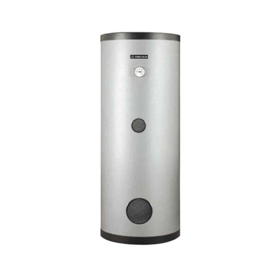
Product description SE Cylinder is intended to hold the domestic hot water. A main unit element is vitreous enamel coated steel tank. Magnesium anode creates additional active anticorrosion protection. Thermal insulation ensures high thermal accumulation. SE Cylinder is suitable for fitting an immersion heater with thermostat (e.g. GRW 1.4, GRW 2.0,..). -
Page 25: Installation
Installation • Cylinder is designed for vertical mounting only (screw on feet). • Connection with water installation must be made after mounting. • Pipes must be made in accordance with diagram in this assembly and operating instructions. Failure to observe the assembly and operating instructions invalidate the warranty and may cause cylinder damage. - Page 26 • safety valve (6 bar) must be installed on cold water inlet (according to the flow direction shown on valve body), • it’s forbidden to install a cut-off valve (or any flow reducer) between storage and the safety valve, • outlet pipe of the safety valve must be opened, directed downward and stay in a place that is not exposed to frost, the outgoing water must be easy to spot, •...
- Page 27 Construction ø500 SE Cylinder construction (140 litres) [6] - sensor pipe [7] - immersion heater connection (cork 1½’’ ) [8] - thermal insulation [9] - thermometer [10] - magnesium anode [11] - upper lid [14] - lower lid [15] - feet C - circulation A-D - dimensions described in data table ø595 (200 l)
- Page 28 ø695 (250, 300 l) SE Cylinder construction 250,300 litres 400,500 litres [6] - sensor pipe [7] - immersion heater connector (cork 1½)’’ [8] - thermal insulation [9] - thermometer ø755 (400 l) [10] - magnesium anode ø854 (500 l) [11] - upper lid [12] - access hole [13] - access hole cover [14] - lower lid...
-
Page 29: Operation
Start-up Check out the pipe connections and make sure that you observe the connection diagrams before start-up. Cylinder filling: • turn on the valve on cold water supply pipe, • turn on the hot water outlet valve (water outflow without the air bubbles indicates that the storage is full) •... -
Page 30: Technical Data
Technical data... - Page 31 PL;DE;FR;GB-042_f.1143...
- Page 32 KOSPEL S.A. 75-136 Koszalin, ul. Olchowa 1 tel. +48 94 31 70 565 serwis@kospel.pl www.kospel.pl...
Need help?
Do you have a question about the SE140 and is the answer not in the manual?
Questions and answers