Table of Contents
Advertisement
Quick Links
INSTALLATION GUIDE
TATE AERLUX
SYSTEM REQUIREMENTS
To ensure the optimum performance and customer satisfaction please adhere to the following:
• Flush out all pipe work prior to installation.
• Installation should comply with relevant local authority requirements.
Operating Pressures
Operating Hot Water Temperatures
Operating Cold Water Temperatures
Failure to comply with the above will void warranties
AS/NZS 3500.1 states that pressures above 500kPa can cause damage from water hammer, reduce the life of appliances, taps & fittings,
cause excessive noise in the system and recommend that a pressure limiting valve (PLV) be fitted.
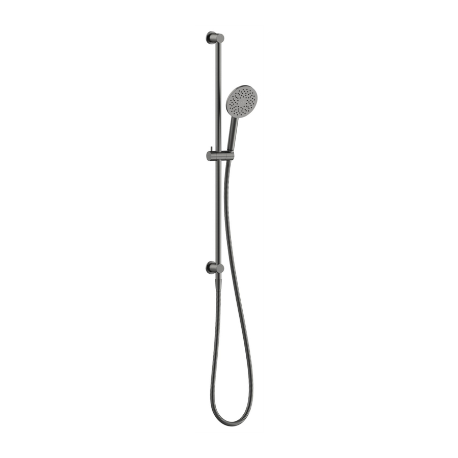
WHAT IS IN THE PACK
2 x Wall Anchors
1 x Elbow
1 x Hose
CHOOSING THE AERLUX™ JET
CONVENTIONAL SLIDE RAIL
TM
2 x Screws
2 x Mounting
1 x 2.5mm
Bracket
Allen Key
1x Flow Regulator
(Pre-fitted to
handpiece)
For a softer shower, install
the Orange Aerlux™ Jet
Hot
70kPa (10.2psi)
2 x Flanges
1 x 12mm
Allen Key
1x Orange
Aerlux™ Jet
With the
For a harder shower, install
Flow Regulator
the Purple Aerlux™ Jet
fitted
MINIMUM
Cold
70kPa (10.2psi)
55° C
5° C
1 x Single Spray
Handpiece
1x Purple
1 x Rail & Slider
Aerlux™ Jet
MAXIMUM
500kPa (72.1)
60° C
N/A
Advertisement
Table of Contents

Subscribe to Our Youtube Channel
Related Manuals for Felton TATE AERLUX


Summary of Contents for Felton TATE AERLUX
- Page 1 INSTALLATION GUIDE TATE AERLUX CONVENTIONAL SLIDE RAIL SYSTEM REQUIREMENTS To ensure the optimum performance and customer satisfaction please adhere to the following: • Flush out all pipe work prior to installation. • Installation should comply with relevant local authority requirements.
- Page 2 HOW TO INSTALL INSTALLING INTO STUD/NOG...(RECOMMENDED) Untighten the grub Screw the mounting brackets into the desired Adjust the bottom bracket on the rail, screws from the top position on the wall (adjustable MAX 820mm c-c), using a 2.5mm allen key to loosen and and bottom of the rail ensuring that they are in the correct orientation.
- Page 3 Figure 1. WATER OUTLET Remove the elbow sleeve from the elbow body. Unscrew the nipple from the elbow with Screw elbow onto the water outlet (wingback) on the wall. Sealant is the 12mm allen key provided and remove required on thread to achieve water tight seal. Ensure the water outlet on the rubber gasket and nipple.
- Page 4 This warranty is e ective for 5 years from the date of purchase and covers supply of replacement parts only, not including installation. You must retain proof of purchase of the product (such as an invoice or receipt) and provide this to Felton on request. This warranty is for manufacturing defects only and does not cover any damage to product due to abuse, negligence or improper installation.
Need help?
Do you have a question about the TATE AERLUX and is the answer not in the manual?
Questions and answers