Advertisement
Quick Links
INTRODUCTION
Thank you for purchasing a Belkin Uninterruptible Power Supply
(UPS). Each year, several natural and man made occurrences put
the power supplied to your electronics in your home or office in
jeopardy. At risk are your hardware, software and data because of
these power problems.
IMPORTANT SAFETY INSTRUCTIONS
Please save this manual!
It contains important operating instructions and warranty information
pertaining to your UPS.
Please save or recycle the packaging materials!
The UPS packaging was designed with great care to provide
protection during shipment and delivery. These materials are
invaluable if you ever have to return the UPS for service. Damage
sustained during transit is not covered under the warranty.
Federal Communications Commission Interference Statement
This equipment has been tested and found to comply with the limits
for a Class B digital device, pursuant to Part 15 of the FCC Rules.
These limits are designed to provide reasonable protection against
harmful interference in a residential installation. This equipment
generates, uses and can radiate radio frequency energy and, if not
installed and used in accordance with the instructions, may cause
harmful interference to radio communications. To assure continued
compliance, use only shielded interface cables when connecting to
computer or peripheral devices. Any changes or modifications not
expressly approved by the party responsible for compliance could
void the user's authority to operate this equipment.
CONTENTS
You should have received the following:
1 – UPS unit
1 – Bulldog Plus Shutdown Software
1 – USB Cable
1 – Phone Line Cable
1 – Coaxial Cable (only F6B550-USB model).
SYSTEM REQUIREMENTS
The UPS can be used without the software and can be used with
any computer using up to a 17" CRT or LCD monitor. Also, you do
not have to have the software installed to utilize the battery backup
outlets.
To fully utilize the UPS and its software, your computer must be able
to operate the following operating systems: Windows98/ ME /NT4 /
2000 /2003 /XP and have a USB port.
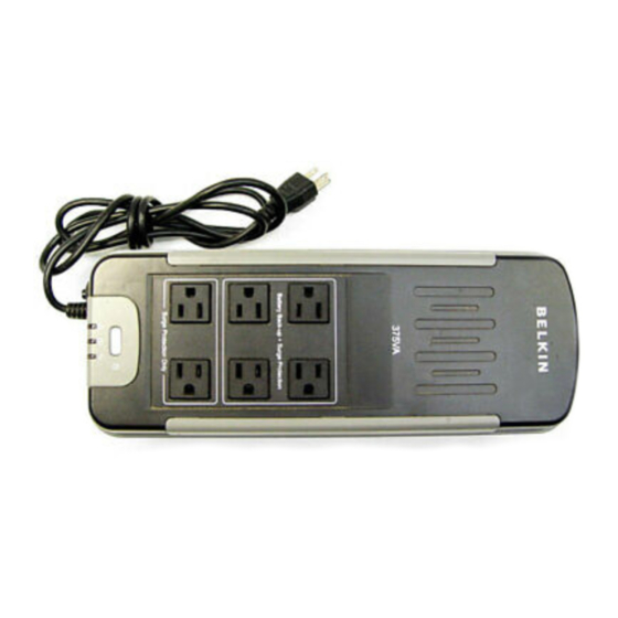
UPS FEATURES AND FUNCTIONS
Before installation, please inspect the UPS upon receipt. Make sure
that nothing is damaged.
Your UPS features 3 LED indicators. Each is marked by a power icon;
please familiarize yourself with this chart, as it will assist you in the
use of your UPS. (See #4 on Diagram 1)
Indicator
Condition
The UPS is operating and
О Solid
supplying the utility power to
Green
connect loads.
ON-LINE
When the UPS is operating from
battery:
1. The light is blinking every 10
seconds if the UPS is
operating on battery mode.
☼ Flashing
2. The light illuminates rapidly
every 1 second if the UPS's
Yellow
battery is very nearly
depleted.
*ON-BATTERY
*LOW-BATTERY
When the UPS is operating and
*REPLACE
supplying the utility power to
BATTERY
connect loads, the LED and
*UPS Fault
buzzer will flash and emit every
1minute if the UPS's battery
needs to be replaced.
The LED will start continuously
О Solid
and the buzzer will be beeping
for 10 seconds if UPS fault is
Yellow
found.
The Site Wiring fault LED will
illuminate when one of the
following conditions exist:
1. Open or high resistance
О Solid
ground
Red
2. Hot and neutral polarities
SITE
WIRING
reversal
FAULT
Chart 1
Fig. 1
Replacement requires removing the battery cover plate on the back or bottom of the UPS. No tools are needed. To replace the batteries:
1.
Remove the battery cover plate on the back of the UPS (Fig.1).
2.
Disconnect the insulated connectors from the battery terminals (Fig.2) then put the battery wire into indentations.
3.
Remove the battery then insert a new battery pack, and push the connectors onto the battery terminals (Fig. 3)
NOTE: There may be a small spark at the battery terminals when reconnecting the connectors. This is normal and will not harm you or the UPS.
4.
Close the battery cover (Fig. 4).
1.
SURGE Protected outlets (See #1 on Diagram 1)
These outlets do not provide power during a power outage.
Do not plug any surge protectors or power strips into the battery
back-up outlets (i.e. daisy chaining).
Equipment such as computer peripherals, printers, fax machine's,
or a desk lamp may be plugged into these outlets. The On/Off
button does not control these outlets.
2.
UPS Outlets (See #2 on Diagram 1)
These outlets are your battery back up outlets. We strongly
recommend that only sensitive equipment such as your computer
and monitor should be plugged into these outlets.
Caution ! Never connect a laser printer or scanner to the
backup outlets of UPS with other computer equipment. A
laser printer or scanner draws significantly more power when
in use than when sitting idle. This may overload the UPS.
Should a power outage occur, your battery backup would
automatically turn on Power (utility or battery) is not supplied to
these outlets when the UPS is switched off.
3.
The On/Off button has 4 functions: (See #3 on Diagram 1)
1. Turns on the UPS. Depress button at least 2 seconds. The
green light will come on.
Description
2. Cold start function. Assuming the battery is charged the UPS
will work without it being plugged into an outlet. Depress and
hold the key for at least 2 seconds to turn on the UPS.
3. Silence function. During "On Battery Mode", the audible sound
can be turned "ON" or "OFF" by depressing the switch less than
1.5 seconds.
4. Battery test function. During "ON Line Mode", depressing the
switch less than 1.5 seconds and the UPS performs a battery
test in back up mode.
#4
#5
1.
AC Input Power Cord (See #1 on Diagram 2)
Provides power to your UPS.
2.
Audio/ Video surge protection port (see #2 on Diagram 2)
(Only F6B550-USB model)
The Audio/ Video cable is surge protected. There is one input port
and one output port.
3.
Phone/ Fax/ Modem Surge Protection (See #3 on Diagram 2)
The Phone/ Fax/Modem lines are surge protected. There is one
input jack and two output jacks. This allows you to split one
telephone connection to two separate devices.
4.
AC Breaker (Circuit Breaker; See #4 on Diagram 2)
Should a power overload occur, the circuit breaker would trigger
the UPS to turn off AC power. In order to restore the power,
depress the circuit breaker button to reset, then depress the
Power button.
5.
USB communication port (see #5 on Diagram 2)
Your UPS features a USB communication port. Installation of the
cable and software is optional. This allows the UPS to connect to
your computer. The Bulldog Software will not work if the UPS is
not connected to you computer. This does not mean the battery
backup feature will not work without the software and cable
installed. The UPS will still provide backup power but you will be
unable to utilize the data management capabilities of the software.
BATTERY REPLACEMENT PROCEDURE
Fig. 2
Fig. 3
○
R
F6H375-USB
F6H550-USB
F6B550-USB
TOP PANEL
#3
#4
#1
#2
Diagram 1
SIDE PANEL
#1
IN
OUT
Refer to Bottom for
Cautionary Marking
AC Input
#2
Phone/Fax/Modem Protection
Circuit Breaker
IN
OUT
OUT
Push to Reset
#3
Diagram 2
Fig. 4
ALARMS
BACK UP (Slow Alarm)
When in "BACK UP" on battery mode, the YELLOW LED
illuminates and the UPS emits an audible alarm. The alarm
stops when the UPS returns to ONLINE normal operation.
LOW BATTERY (Rapid Alarm)
In "BACK UP" mode, when the battery energy runs low, the
UPS beeps rapidly until the UPS shuts from a depleted battery
or returns to LINE NORMAL operation.
FAULT (10 Seconds Continuously)
When the UPS occur fault, the UPS emits an audible alarm for
10 seconds continuously to warn of a fault condition.
Disconnect the equipment prior to checking the equipment.
INSTALLATION
Note!
Before installation, please inspect the UPS Upon
receipt. Make sure that everything inside the package
is not damaged.
A) Connect to AC Utility Power
1.
Connect the AC inlet to utility power via the
power cord. Please make sure there are no
devices plugged into the UPS unit. Check to
see if the "Site Wiring Fault" indicator is lit or
not. If it is lit, please have the utility wiring
inspected by an electrician.
B) Charge the Battery
1.
For best results, charge the battery for 8 hours prior to initial
use. The UPS charges its battery whenever it is connected to
the utility power.
C) Turn on the UPS
1.
Turn on your UPS by depressing the On/Off button for
approximately 2 seconds. You will see the green indicator light
come on.
D) Plug in Power Devices
1.
Plug your devices into the AC outlets on the UPS. To use the
UPS as a master on/off switch, make sure all of the loads are
switched on.
Caution: Never connect a laser printer
or scanner to the backup outlets of UPS
with other computer equipment. A laser
printer or scanner draws significantly
more power when in use than when
idles. This may overload the UPS.
E) Connect the phone/ fax/ modem lines
1.
Connect a single phone / fax/ modem line into the surge
protected sockets on the side of the UPS. The RJ-11 modular
sockets accept standard single line telephone connections.
2.
Plug one end of the phone cable you received into your
telephone wall jack and plug the other end into the jack marked
IN. You may now plug a phone, fax or modem into the two
jacks marked OUT. (See Diagram 3)
Phone/Fax/Modem Protection
IN
OUT
OUT
Modem/ Fax
To Telephone Socket
Phone
Diagram 3
Note: This connection is optional but highly suggested as phone/
fax/ modem lines often carry dangerous surges and spikes. The
UPS works properly without a phone/ fax/ modem connection.
Caution: The phone/fax/modem protection feature could be rendered
inoperable if improperly installed. Make sure that the telephone line
from the wall is plugged into the connector marked "IN", and the
devices to be protected (phone/ fax/ modem) are plugged into the
connector marked " OUT".
F) Connect the CATV cable (see #2 on Diagram 2)
(Only F6B550-USB model)
1.
Connect a single CATV cable into the surge protect port on
the left of the UPS. The Audio/ Video modular port can
accept the standard single cable of CATV connects.
2.
Plug one end of the CATV cable you received into your CATV
wall port and plug the other end into the port marked IN. You
can plug television into the one port marked OUT.
Note: The UPS works properly without the Audio/ Video connection.
G) Connect the USB (Universal Serial Port) Communication
port (see #5 on Diagram 2)
A USB port is provided to relay the signal to support Windows. To
fully utilize the Bulldog Shutdown Software; you will need to
connect the UPS to your computer. Connect the USB cable to
your UPS then connect the other end to the USB port on your
computer.
H) Install the Software (Optional)
a)
To fully utilize the UPS and its software, your computer must be
able to operate the following operating systems: Windows98/
ME / NT4/ 2000/ 2003/ XP and have a USB port.
b)
Your UPS features the Bulldog Plus Shutdown Software. This
allows you to protect and save your data should a power
outage occur, as well as safely shutdown your computer in your
absence. Please be sure to close out of all applications prior to
installing the software.
1.
To install the software, please place the CD into the CD drive of
your computer.
2.
Your computer should autorun the CD. If this does not occur, go
to the Run feature on your Start icon (lower left corner) on your
screen. Please enter the CD drive, it may be D: Upon entering
the drive run setup.exe. to execute the software. Should you
continue to have a problem, please refer to your computer's
owner's manual for the correct drive.
Laser Printer
Advertisement

Related Manuals for Belkin F6H375-USB


Summary of Contents for Belkin F6H375-USB
- Page 1 INTRODUCTION Thank you for purchasing a Belkin Uninterruptible Power Supply (UPS). Each year, several natural and man made occurrences put the power supplied to your electronics in your home or office in jeopardy. At risk are your hardware, software and data because of these power problems.
- Page 2 F, charge the UPS battery every 3 months. Note: Away from sunlight Away from heat Away from water © 2003 Belkin Components. All rights reserved. All trade names are registered trademarks of respective manufacturers listed. TECHNICAL SPECIFICATIONS F6H375 F6H550 Model -USB...