Table of Contents
Advertisement
Quick Links
Thank you for your purchase of the Larson Electronics:
PDU-ATS-100A-208Y.120-3PH, 100-amp Automatic Transfer Switch
WARNING:
READ CAREFULLY BEFORE INSTALLING FIXTURE. RETAIN THESE INSTRUCTIONS FOR FUTURE REFERENCE.
CRITICAL SAFETY INSTRUCTIONS:
INSTALLATION SHOULD ONLY BE CONDUCTED BY A QUALIFIED ELECTRICIAN IN ACCORDANCE WITH NEC AND ANY
•
RELEVANT LOCAL BUILDING CODES.
RISK OF FIRE OR ELECTRIC SHOCK. FIXTURE INSTALLATION REQUIRES KNOWLEDGE OF ELECTRICAL SYSTEMS. IF
•
NOT QUALIFIED, CONTACT A QUALIFIED ELECTRICIAN.
•
BE CERTAIN ELECTRICAL POWER IS OFF BEFORE AND DURING INSTALLATION AND MAINTENANCE.
•
MAKE SURE THE SUPPLY VOLTAGE IS THE SAME AS THE RATED FIXTURES VOLTAGE.
•
TO PREVENT WIRING DAMAGE OR ABRASION, DO NOT EXPOSE WIRING TO EDGES OF SHEET METAL OR SHARP
OBJECTS. SUITABLE FOR DAMP LOCATIONS.
The standard switch enclosure is a National Electrical Manufacturer's Association (NEMA) and UL 3R type. UL and NEMA 3R type
enclosures primarily provide a degree of protection against falling rain and sleet; undamaged by the formation of ice on the enclosure.
Before installing, operating or servicing this equip-ment, read the SAFETY RULES (inside front cover) carefully. Comply strictly with all
SAFETY RULES to prevent accidents and/or damage to the equip-ment. The manufacturer recommends a copy of the SAFETY
RULES are made and posted near the trans-fer switch. Also, be sure to read all instructions and information found on tags, labels and
decals affixed to the equipment.
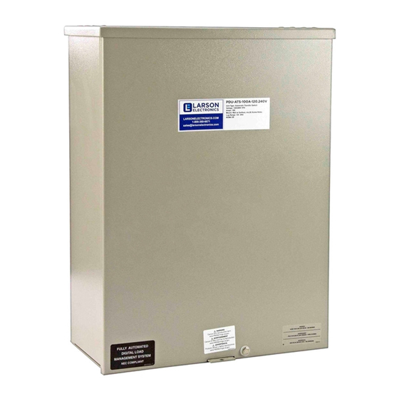
The Larson Electronics PDU-ATS-100A-208Y.120-3PH Automatic Transfer Switch is ideal for managing electrical loads between two
sources in industrial facilities. This 100-amp, 208Y/120 three-phase controller handles timing, sensing, exercise functions and transfer
commands. Constructed of aluminum, the unit is housed in a NEMA 3R enclosure.
MOUNTING
PDU-ATS-100A-208Y.120-3PH are wall-mounted or surface-mounted. Install the transfer switch as close as possible to
the electrical loads that are to be connected to it. Mount the switch vertically to a rigid supporting structure. To prevent
switch distortion, level all mounting points. If necessary, use washers behind mounting holes to level the unit.
3-POLE-MECHANISM
These switches (Figure 1) are used with a three phase system,
when the three phase NEUTRAL line is to be connected to a
NEUTRAL lug and is not to be switched.
Solderless, screw-type terminal lugs are standard.
The conductor size range is as follows:
Switch Rating
100 A
200A
Conductor sizes must be adequate to handle the max-imum current to
which they will be subjected; based on the 75°C column of tables,
charts, etc. used to size conductors. The installation must comply fully
with all applicable codes, standards and regulations.
Larson Electronics, LLC
100-amp Automatic Transfer Switch
208Y/120 3PH - Aluminum - NEMA 3R
Instruction Manual
Wire Range
#6-2/0 AWG
#4-400 MCM
Phone: (800) 369-6671
Fax: (903) 498-3364
PDU-ATS-100A-208Y.120-3PH
www.larsonelectronics.com
1 of 13
Advertisement
Table of Contents

Subscribe to Our Youtube Channel
Related Manuals for Larson Electronics PDU-ATS-100A-208Y.120-3PH


Summary of Contents for Larson Electronics PDU-ATS-100A-208Y.120-3PH
- Page 1 RULES are made and posted near the trans-fer switch. Also, be sure to read all instructions and information found on tags, labels and decals affixed to the equipment. The Larson Electronics PDU-ATS-100A-208Y.120-3PH Automatic Transfer Switch is ideal for managing electrical loads between two sources in industrial facilities. This 100-amp, 208Y/120 three-phase controller handles timing, sensing, exercise functions and transfer commands.
-
Page 2: Connecting Start Circuit Wires
PDU-ATS-100A-208Y.120-3PH POWER • PDU-ATS-100A-208Y.120-3PH is compatible with input voltages of 208Y/120 3PH. • Power source and load connec-tions are made at a transfer mechanism, inside the switch enclosure. Before connecting wiring cables to terminals, remove any surface oxides from the cable ends with a wire brush. All power cables should enter the switch next to transfer mechanism terminals. -
Page 3: Manual Operation
— DO NOT FORCE. Release handle slowly to allow the spring in the switch box to relax. “ON” now appears in the "UTILITY" window and “OFF” appears in the "STANDBY" window. Larson Electronics, LLC Phone: (800) 369-6671 Fax: (903) 498-3364 www.larsonelectronics.com... -
Page 4: Close To Emergency Source Side
UTILITY supply to the transfer switch. 6. Set the generator’s main circuit breaker (CB1) to its OFF or OPEN position. 7. Set the AUTO/OFF/MANUAL switch to the OFF position to shut down the generator. Larson Electronics, LLC Phone: (800) 369-6671 Fax: (903) 498-3364 www.larsonelectronics.com... -
Page 5: Generator Tests Under Load
8. Turn on the utility power supply to transfer switch, using whatever means provided (such as a utility main line circuit breaker). The utility power source now powers the loads. 9. Set the generator's AUTO/OFF/MANUAL switch to its AUTO position. The system is now set for fully automatic operation. Larson Electronics, LLC Phone: (800) 369-6671 Fax: (903) 498-3364 www.larsonelectronics.com... - Page 6 PDU-ATS-100A-208Y.120-3PH Section 5 — Mounting Dimensions RTS “W” Type Transfer Switch Mounting Dimensions - 100/200A 208V Larson Electronics, LLC Phone: (800) 369-6671 Fax: (903) 498-3364 www.larsonelectronics.com 6 of 13...
- Page 7 PDU-ATS-100A-208Y.120-3PH Section 5 — Mounting Dimensions RTS “W” Type Transfer Switch Mounting Dimensions - 100A 480V Larson Electronics, LLC Phone: (800) 369-6671 Fax: (903) 498-3364 www.larsonelectronics.com 7 of 13...
-
Page 8: Section 5 - Mounting Dimensions
PDU-ATS-100A-208Y.120-3PH Section 5 — Mounting Dimensions RTS “W” Type Transfer Switch Mounting Dimensions - 200A 480V Larson Electronics, LLC Phone: (800) 369-6671 Fax: (903) 498-3364 www.larsonelectronics.com 8 of 13... - Page 9 PDU-ATS-100A-208Y.120-3PH Section 6 — Electrical Data RTS “W” Type Transfer Switch Interconnection Diagram 057329-T Larson Electronics, LLC Phone: (800) 369-6671 Fax: (903) 498-3364 www.larsonelectronics.com 9 of 13...
- Page 10 F1,F2 - FUSE 5A SENSING NOTES: 1.) ALL CONTACTS SHOWN WITH TRANSFER SWITCH IN UTILITY POSITION. 2.) FOR SINGLE PHASE OPERATION, ADD JUMPER WIRE FROM PM TERMINALS 1 TO 8. Larson Electronics, LLC Phone: (800) 369-6671 Fax: (903) 498-3364 www.larsonelectronics.com 10 of 13...
- Page 11 PDU-ATS-100A-208Y.120-3PH Section 6 — Electrical Data RTS “W” Type Transfer Switch Wiring Diagram/Schematic 100/200A, 208V Larson Electronics, LLC Phone: (800) 369-6671 Fax: (903) 498-3364 www.larsonelectronics.com 11 of 13...
- Page 12 TS - TERMINAL STRIP (CUSTOMER CONNECTION) NOTES: LS1,LS2,LS3 - LIMIT SWITCHES, ACTUATOR 1.) ALL CONTACTS SHOWN WITH F1,F2 - FUSE 5A SENSING TRANSFER SWITCH IN UTILITY TR1,TR2 - TRANSFORMER STEP DOWN POSITION. Larson Electronics, LLC Phone: (800) 369-6671 Fax: (903) 498-3364 www.larsonelectronics.com 12 of 13...
- Page 13 PDU-ATS-100A-208Y.120-3PH Section 6 — Electrical Data RTS “W” Type Transfer Switch Wiring Diagram/Schematic 100/200A, 480V 47822-T Larson Electronics, LLC Phone: (800) 369-6671 Fax: (903) 498-3364 www.larsonelectronics.com 13 of 13...
-
Page 14: Replacement Parts
Larson Electronics. THESE INSTRUCTIONS MAY NOT COVER ALL DETAILS OR VARIATIONS OF THIS PRODUCT FOR YOUR EQUIPMENT OR INSTALLATION REQUIREMENTS. SHOULD FURTHER INFORMATION NOT COVERED BY THESE INSTRUCTIONS BE REQUIRED, PLEASE CONTACT LARSON ELECTRONICS BY EMAIL AT SALES@LARSONELECTRONICS.COM OR BY PHONE AT 1-800-369-6671 FOR FURTHER ASSISTANCE.
Need help?
Do you have a question about the PDU-ATS-100A-208Y.120-3PH and is the answer not in the manual?
Questions and answers