Table of Contents
Advertisement
Available languages
Available languages
Installer: Leave this manual with the appliance. Consumer: Retain this manual for future reference.
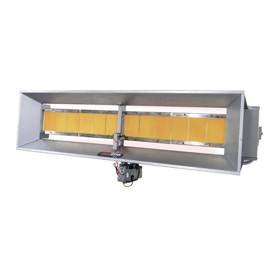
OPERATING INSTRUCTIONS AND OWNER'S MANUAL
HEATSTAR High-Intensity Infrared Heaters
HS4030 HS8070
HS4040 HS9080 HS9120
HS8050 HS9090 HS9140
HS8060 HS9100S
4000 & 8000 Models
If the information in this manual is not followed exactly, a fire or explosion
WARNING:
may result causing property damage, personal injury or loss of life.
— Donotstoreorusegasolineorotherflammablevaporsandliquidsinthevicinityofthisorany
other appliance.
— WHATTODOIFYOUSMELLGAS
• OpenWindows
• DO NOT try to light any appliance.
• DO NOT use electrical switches.
• DO NOTuseanytelephoneinyourhouse.Immediatelycallyourlocalgassupplierfroma
telephoneremotefromtheareaoftheleak.Followthegassupplier'sinstructions.
• DO NOT touch any electrical switch; do not use any phone in your building.
• Installationandservicemustbeperfomedbyaqualifiedinstaller,serviceagencyorthegas
supplier.
• Ifyoucannotreachyourgassupplier,calltheFireDepartment.
WARNING:
Improperinstallation,adjustment,alteration,serviceormaintenancecancauseproperty
damage, injury or death. Read the installation, operation, and maintenance instructions thoroughly before
installingorservicingthisheater.Forassistanceoradditionalinformationconsultaqualifiedinstaller,service
agency, or gas supplier.
Thisisanunventedgas-firedheater.Itusesair(oxygen)fromtheareainwhichitisused.Adequate
combustionandventilationairmustbeprovided.Refertopage5.
READ INSTRUCTIONS CAREFULLY: Read and follow all
HS9100
instructions. Place instructions in a safe place for future
reference. Do not allow anyone who has not read these
instructions to assemble, light, adjust or operate the heater.
ENERCOGROUPINC.,4560W.160THST.,CLEVELAND,OHIO44135•866-447-2194
9000 Models
Advertisement
Chapters
Table of Contents

Related Manuals for Enerco HEATSTAR HS4030


Summary of Contents for Enerco HEATSTAR HS4030
- Page 1 • DO NOT touch any electrical switch; do not use any phone in your building. • Installationandservicemustbeperfomedbyaqualifiedinstaller,serviceagencyorthegas supplier. • Ifyoucannotreachyourgassupplier,calltheFireDepartment. WARNING: Improperinstallation,adjustment,alteration,serviceormaintenancecancauseproperty damage, injury or death. Read the installation, operation, and maintenance instructions thoroughly before installingorservicingthisheater.Forassistanceoradditionalinformationconsultaqualifiedinstaller,service agency, or gas supplier. Thisisanunventedgas-firedheater.Itusesair(oxygen)fromtheareainwhichitisused.Adequate combustionandventilationairmustbeprovided.Refertopage5. ENERCOGROUPINC.,4560W.160THST.,CLEVELAND,OHIO44135•866-447-2194...
-
Page 2: Table Of Contents
Pages F1 — F16 Troubleshooting ..............7 Connection diagram for flame rod current for flame rectification systems ........8 Replacement parts ............9 Control system replacement parts ........12 Enerco Group, Inc. |Gas-Fired Infra-Red Space Heaters Operating Instructions and Owner’s Manual... -
Page 3: General Information
INSTALLATIONSWHEREPARKEDVEHICLESARE DIRECTLYBELOWTHEHEATER. ¾3/4”MAXIMUMTHREADLENGTH Figure 2. 3. SUSPENSION ½”BLACKPIPE Gas valve Heaterhasfourmountingholes,twooneachend,for connection attaching rod or angle iron brackets and shall be safely requirements andadequatelyfixedinpositionindependentofgas andelectricsupplylines.RefertoFigures4,5,and7on TOGASVALVEBODY Enerco Group, Inc. | Gas-Fired Infra-Red Space Heaters Operating Instructions and Owner’s Manual... -
Page 4: Gas Pressure
100,000 Horiz.-45° 44” 40” 40” 104” 9120* 120,000 120,000 Horiz.-45° 46” 46” 46” 1 14” 9140** 140,000 – Horiz.-45° 46” 46” 46” 1 14” *HighIntensityHeatersareonlysoldas4040,8060,9100S,and9120 **Differentmodelnumbersareachievedbyusingsupplementalorificesincludedwithheaterstochangeheatoutput. Theclearancestocombustiblesrepresentasurfacetemperatureof90°F(32°C)aboveroomtemperature.Buildingmaterialswithlowheat tolerancemaybesubjecttodegradationatlowertemperatures.Itistheinstaller’sresponsibility. Enerco Group, Inc. |Gas-Fired Infra-Red Space Heaters Operating Instructions and Owner’s Manual... -
Page 5: Electrical
100,000 100,000 7.0” 11” 14” 14” 4.3” 10” 9120 120,000 120,000 7.0” 11” 14” 14” 5.8” 10” 9140 140,000 – 7.0” – 14” – 5.5” – – Enerco Group, Inc. | Gas-Fired Infra-Red Space Heaters Operating Instructions and Owner’s Manual... -
Page 6: Thermostat
1. TurnthermostattoOFF. The gas control should be replaced if: 2. TurnmanualgascontrolknobongasvalvetoPILOT a.Itdoesnotperformproperlyoncheckoutor position. troubleshooting. 3. PartiallydepressknobandrotatetotheOFFposition. b.Thegascontrolknobishardtoturnorpushdown,orit 4. Closegassupplyvalves. fails to pop back up when released. Enerco Group, Inc. |Gas-Fired Infra-Red Space Heaters Operating Instructions and Owner’s Manual... - Page 7 00288A LPtoNGKit 8060 00283A NGtoLPKit 9100S 00291A NGtoLPKit 9100S 00284A LPtoNGKit 9100S 00292A LPtoNGKit 9100S 00281A NGtoLPKit 9120 00289A NGtoLPKit 9120 00282A LPtoNGKit 9120 00290A LPtoNGKit 9120 Enerco Group, Inc. | Gas-Fired Infra-Red Space Heaters Operating Instructions and Owner’s Manual...
-
Page 8: Connection Diagram For Flame Rod Current For Flame Rectification Systems
LINE VOLTAGE 24 VOLT THERMOSTAT THERMOSTAT FENWALL OPTIONAL OPTIONAL IGNITION MODULE 120VAC 24VAC TRANSFORMER (SHIPPED LOOSE) NG/LP Conversion Kits STOCK# DESCRIPTION 00152 NGRateConversionKit-30Kto40KBTU/HR 00153 LPRateConversionKit-30Kto40KBTU/HR 00275 GasConversionKit-NGtoLP 00276 GasConversionKit-LPtoNG Enerco Group, Inc. |Gas-Fired Infra-Red Space Heaters Operating Instructions and Owner’s Manual... -
Page 9: Replacement Parts
Stock No. Description Req’d. 00442A ReflectorAssembly 02524A BurnerAssembly 03421P Venturi 05429 Orifice–Br.N.G.8070 05430 Orifice–Br.N.G.8060 05430 Orifice–Br.N.G.8050 05443 Orifice–Br.L.P.8060 05445 Orifice–Br.L.P.8050 12366 Gasket–Venturi 8070Nat.Gas 8060Nat.Gas 8050Nat.Gas 8060Propane 8050Propane Enerco Group, Inc. | Gas-Fired Infra-Red Space Heaters Operating Instructions and Owner’s Manual... - Page 10 4000 Series Models and 8000 Series Models ONLY Grid 4000 Series Models F104440 GRIDKIT Grid,Screws,RetentionClip Reflector F104441 RETROGRIDKIT Reflector,Grid,Screws, RetentionClip,RateTag 4000SERIES 8000 Series Models F104445 GRIDKIT Grid,Screws,RetentionClip F104446 RETROGRIDKIT Reflector,Grid,Screws, RetentionClip,RateTag 8000SERIES Enerco Group, Inc. |Gas-Fired Infra-Red Space Heaters Operating Instructions and Owner’s Manual...
- Page 11 Orifice–Br.N.G.9100S 05432 Orifice–Br.N.G.9090 05437 Orifice–Br.N.G.9080 05446 Orifice–Br.L.P.9100S 05447 Orifice–Br.L.P.9090 05449 Orifice–Br.L.P.9080 06398 ManifoldAssembly 12366 Gasket–Venturi 14639 CenterSaddleBracket 11381 CenterSupportAssembly 9100SNat.Gas 9090Nat.Gas 9080Nat.Gas 9100SPropane 9090Propane 9080Propane 10 11 Enerco Group, Inc. | Gas-Fired Infra-Red Space Heaters Operating Instructions and Owner’s Manual...
-
Page 12: Control System Replacement Parts
REPLACEMENT PARTS LIST FOR CONTROL SYSTEM SUFFIX SPARK MODELS ITEM STOCK DESCRIPTION REQ’D 00063 IGNITIONMODULE,FENWAL 00037 GASVALVE-NG 00236 CONTROLASSY.NG 05383 ORIFICEPILOT–NG 08353 TRANSFORMER40VA 11385 PILOTBURNERASSY. 14619 MOUNTINGBRACKET 16453 PILOTTUBEW/FITTINGS Enerco Group, Inc. |Gas-Fired Infra-Red Space Heaters Operating Instructions and Owner’s Manual... - Page 13 REPLACEMENT PARTS LIST FOR CONTROL SYSTEM SUFFIX SP ITEM STOCK DESCRIPTION REQ’D 00063 IGNITIONMODULE,FENWAL 00036 GASVALVE-LP 00336 CONTROLASSY.LP 05384 ORIFICEPILOT–LP 08353 TRANSFORMER40VA 11385 PILOTBURNERASSY. 14619 MOUNTINGBRACKET 16453 PILOTTUBEW/FITTINGS Enerco Group, Inc. | Gas-Fired Infra-Red Space Heaters Operating Instructions and Owner’s Manual...
- Page 14 STOCK DESCRIPTION REQ’D 00024 GASVALVE-NG 00025 GASVALVE-LP 05384 ORIFICEPILOTLP 05383 ORIFICEPILOTNG 09360 THERMOCOUPLEPPHONEYWELL 10367 THERMOSTAT“PP”HEATSTAR 11385 PILOTBURNER-9000HTR 16454 PILOTTUBEWITHFITTINGS PPNG PPLP NOTE:1–WHENORDERINGSPAREPARTSALWAYSGIVEHEATER MODELNO.,STOCKNO.,SERIALNO.,ANDTYPEOR GASUSED. 2–WHENDISASSEMBLINGPARTSFROMHEATERFORRE- PAIR,CAREFULLYNOTEORIENTATIONOFPARTS,AND THENREVERSEPROCEDUREWHENASSEMBLING. Enerco Group, Inc. |Gas-Fired Infra-Red Space Heaters Operating Instructions and Owner’s Manual...
- Page 15 RECOMMENDUSING HEATERHANGING BRACKETF1 14581 SEECHAINKIT #17374OR THREADEDROD FROM HORIZONTAL MAXIMUM 45° HEATERSIDEREFLECTORMUST BEPARALLELTOTHEFLOOR TYPICAL BEAM MOUNT SUGGESTEDHANGINGMETHOD MODEL:4000,8000,9000,MH40 WHENANGLEMOUNTING BEAMCLAMP ELEVATEONLYDESIGNATED F114581HANGING THREADEDROD SIDEOFHEATER BRACKETKIT ORCHAIN KIT17374 Enerco Group, Inc. | Gas-Fired Infra-Red Space Heaters Operating Instructions and Owner’s Manual...
- Page 16 Somestatesdonotallowtheexclusionorlimitationofincidentalorconsequentialdamages,so theabovelimitationorexclusionmaynotapplytoyou.ThisWarrantygivesyouspecificlegal rights,andyoumayhaveotherrightswhichvaryfromstatetostate. reservestherighttomakechangesatanytime,withoutnoticeor EnercoGroup,Inc., obligation, in colors, specifications, accessories, materials and models. PRODUCTREGISTRATION:Thankyouforyourpurchase. Pleaselogintohttp://www.egiregistration.comtoregisteryourproduct. ENERCOGROUP,INC.,4560W.160THST.,CLEVELAND,OHIO44135•866-447-2194 Mr.HeaterisaregisteredtrademarksofEnercoGroup,Inc. ©2020,EnercoGroup,Inc.Allrightsreserved Enerco Group, Inc. |Gas-Fired Infra-Red Space Heaters Operating Instructions and Owner’s Manual...
- Page 17 • NE PAS tenterd'allumerl'appareil. • NE PASutiliserlesinterrupteursélectriques. • N E PAS utiliseruntéléphonedansvotremaison.Appelezimmédiatementvotrefournisseur degazàpartirdutéléphoned'unvoisin.Suivezlesinstructionsdufournisseurdegaz. • NE TOUCHEZ àaucuninterrupteurélectrique;n’utilisezaucuntéléphonedansvotreimmeuble. • L ’installationetl'entretiendoiventêtreeffectuésparuninstallateurqualifié,uneagencede serviceoulefournisseurdegaz. • Sivousnepouvezpasjoindrevotrefournisseurdegaz,appelezlespompiers. AVERTISSEMENT : Uneinstallation,unréglageunemodification,uneréparationouunentretienincorrectpeutentraînerdes dommagesmatériels,desblessuresoulamort.Lisezattentivementlesinstructionsd'installation,defonctionnementetd'entretienavantde procéderàl'installationouàl'entrentiendecetintensité.Pourdel'aideoudesrenseignementssupplémentaires,consultezuninstallateur qualifié,uneagencedeserviceoulefournisseurdegaz. Ils'agitd'unradiateurnonventiléalimentéaugaznaturel.Ilutilisel'air(oxygène)delazonedanslaquelleil fonctionne.Ondoitassurerunapportsuffisantd'airdecombustionetdeventilation.Reportez-vousàlapage5. ENERCOGROUPINC.,4560W.160THST.,CLEVELAND,OHIO44135•866-447-2194...
- Page 18 Pressiondugaz ................F4 ANGLAIS Systèmeélectrique ..............F5 Pages E1 — E16 Thermostatetemplacement ............F5 ESPAGNOL Ventilation .................F5 Pages S1 — S16 Fonctionnement .................F5 Informationsurlenettoyage ............F5 FRANÇAIS Thermostat ................F6 Pages F1 — F16 Dépannage ................F7 Schémadeconnexionducourantdudétecteurdeflamme pourlessystèmesderectificationdelaflamme....F8 Piècesderechange..............F9 Piècesderechangedusystèmedecontrôle......F12 EnercoGroup,Inc.|Radiateursinfrarougesàforteintensité Guided’utilisationetmanueldupropriétaire...
-
Page 19: Informations Générales
UTILISEZ UNE QUANTITÉ MODÉRÉE DE PÂTE À JOINT plusgrandedoitêtreutilisée.AuCanada,reportez-vousàla normeACCB149-1-M91. AVERTISSEMENT : RESPECTERLESDÉGAGEMENTS ILLUSTRÉSÀLAFIGURE1OUSURLAPLAQUE SIGNALÉTIQUEDURADIATEURDANSLESINSTALLATIONS LAISSEZLESDEUXPREMIERSFILETAGESDÉNUDÉS DEGARAGEOÙLESVÉHICULESSTATIONNÉSSONT 1,9¾CM(3/4PO)LONGUEUR DIRECTEMENTAU-DESSOUSDURADIATEUR. DEFILETAGEMAXIMUM 3. SUSPENSION TUYAUNOIRDE1,2CM Leradiateuraquatretrousdemontage,deuxàchaqueextré- (½PO) Figure 2. mité,pourfixerlatigeoul'équerredefixationsmétalliqueset Exigences de doitêtrefixéd'unemanièresuffisammentsûredansuneposi- raccordement tionindépendantedesconduitesd'alimentationengazeten CORPSDELAVALVEÀGAZ de la valve de gaz EnercoGroup,Inc.|Radiateursinfrarougesàforteintensité Guided’utilisationetmanueldupropriétaire... -
Page 20: Pression Du Gaz
2,9m(114po) 9100S* 100000 100000 Horiz.-45° 1,22m(48po) 1,16m(46po) 1,16m(46po) 3m(118po) 9100** 100000 100000 Horiz.-45° 1,12m(44po) 1,02m(40po) 1,02m(40po) 2,7m(104po) 9120* 120000 120000 Horiz.-45° 1,16m(46po) 1,16m(46po) 1,16m(46po) 2,9m(114po) 9140** 140000 – Horiz.-45° 1,16m(46po) 1,16m(46po) 1,16m(46po) 2,9m(114po) *Seulslesmodèlesderadiateursàhauteintensitésuivantssontvendus:4040,8060,9100Set9120 **Ilestpossibled'obtenirlesautresnumérosdemodèleenutilisantlesorificessupplémentairesinclusaveclesradiateurspourmodifierlaproductiondechaleur. Lesdégagementsauxcombustiblesreprésententunetempératuredesurfacede90°F(32°C)supérieureàlatempératureambiante.Les matériauxdeconstructionavectoléranceàlachaleurbassepeutêtresoumisàunedégradationàdestempératuresinférieures.Ilestdela responsabilitédel'installateur EnercoGroup,Inc.|Radiateursinfrarougesàforteintensité Guided’utilisationetmanueldupropriétaire... -
Page 21: Système Électrique
25,4cm 9100 100000 100000 (7po) (11po) (14po) (14po) (4,3po) (10po) 18cm 28cm 35,6cm 35,6cm 14,7cm 25,4cm 9120 120000 120000 (7po) (11po) (14po) (14po) (5,8po) (10po) 18cm 35,6cm 14cm 9140 140000 – – – – – (7po) (14po) (5,5po) EnercoGroup,Inc.|Radiateursinfrarougesàforteintensité Guided’utilisationetmanueldupropriétaire... -
Page 22: Thermostat
Lesappareilsquisontutilisésdefaçonsaisonnièredoiventêtrevérifiés liantàjointquiémetcetteodeuroucettevapeur.Aprèsenviron avantlamiseàl’arrêtetdenouveauavantlaprochaineutilisation. 20minutes,cetteodeurdisparaîtraetnesereproduiraplus. Environnementpoussiéreux,humideoucorrosif.Étantdonnéque 13. MISE À l’ARRÊT cesenvironnementspeuventdétériorerplusrapidementlecontrôle dugaz,lesystèmedoitêtrevérifiéplussouvent. 1. Réglezlethermostatà O FF. Le contrôle du gaz doit être remplacé si : 2. Tournezleboutondecontrôledegazmanuelsurlavalvede a. Ilnefonctionnepascorrectementlorsdelavérificationoudu gazàlapositionPILOT. dépannage. 3. Enfoncezpartiellementleboutonettournez-leàlapositionOFF. b. Leboutondecontrôledugazpeutdifficilementêtretournéou 4. Fermezlesvalvesd'alimentationengaz. enfoncé,ous'ilneparvientpasàrebondirunefoisrelâché. EnercoGroup,Inc.|Radiateursinfrarougesàforteintensité Guided’utilisationetmanueldupropriétaire... - Page 23 LPtoNGKit 4040 00279A NGtoLPKit 8060 00287A NGtoLPKit 8060 00280A LPtoNGKit 8060 00288A LPtoNGKit 8060 00283A NGtoLPKit 9100S 00291A NGtoLPKit 9100S 00284A LPtoNGKit 9100S 00292A LPtoNGKit 9100S 00281A NGtoLPKit 9120 00289A NGtoLPKit 9120 00282A LPtoNGKit 9120 00290A LPtoNGKit 9120 EnercoGroup,Inc.|Radiateursinfrarougesàforteintensité Guided’utilisationetmanueldupropriétaire...
-
Page 24: Schéma De Connexion Du Courant Du Détecteur De Flamme
IND/ V1/PV1 TH/W THERMOSTAT DE TENSION 24 VOLT DE LIGNE THERMOSTAT FENWALL OPTIONNEL EN OPTION MODULE D'ALLUMAGE 120VAC 24VAC TRANSFORMER (SHIPPED LOOSE) Kits de conversion NG / LP STOCK# DESCRIPTION 00152 KitdeConversiondeTauxNG-30Kà40KBTU/HR 00153 KitdeConversiondeTauxLP-30Kà40KBTU/HR 00275 KitdeConversiondeGaz-NGàLP 00276 KitdeConversiondeGaz-LPàNG EnercoGroup,Inc.|Radiateursinfrarougesàforteintensité Guided’utilisationetmanueldupropriétaire... - Page 25 Liste des pièces de rechange pour les radiateurs Modèles des séries 8000 / Moins de contrôle Article No de Description requis stock 00442A Réflecteur 02524A Brûleur 03421P Venturi 05429 Orifice–Br.G.N.8070 05430 Orifice–Br.G.N.8060 05430 Orifice–Br.G.N.8050 05443 Orifice–Br.G.P.L.8060 05445 Orifice–Br.G.P.L.8050 12366 Joint–Venturi 8070Nat.Gas 8060Nat.Gas 8050Nat.Gas 8060Propane 8050Propane EnercoGroup,Inc.|Radiateursinfrarougesàforteintensité Guided’utilisationetmanueldupropriétaire...
-
Page 26: Piècesderechange
Pièces de rechange pour kits rétro de grilles Retention Clip Modèles série 4000 et modèles série 8000 SEULEMENT Grid Modèles des séries 4000 F104440 KITGRID Grille,Vis,ClipRetention Reflector F104441 KITRÉTROGRILLE Réflecteur,Grille,Vis, Clipderétention,Tagdetaux 4000SERIES Modèles des séries 8000 F104445 KITGRID Grille,Vis,ClipRetention F104446 RETROGRIDKIT Réflecteur,Grille,Vis, Clipderétention,Tagdetaux 8000SERIES F-10 EnercoGroup,Inc.|Radiateursinfrarougesàforteintensité Guided’utilisationetmanueldupropriétaire... - Page 27 Brûleur 03421P Venturi 05431 Orifice–Br.G.N.9100S 05432 Orifice–Br.G.N.9090 05437 Orifice–Br.G.N.9080 05446 Orifice–Br.G.P.L.9100S 05447 Orifice–Br.G.P.L.9090 05449 Orifice–Br.G.P.L.9080 06398 Collecteur 12366 Joint–Venturi 14639 Support de centre de selle 1 1381 Support central 9100SNat.Gas 9090Nat.Gas 9080Nat.Gas 9100SPropane 9090Propane 9080Propane 10 11 F-11 EnercoGroup,Inc.|Radiateursinfrarougesàforteintensité Guided’utilisationetmanueldupropriétaire...
- Page 28 LISTE DES PIÈCES DE RECHANGE POUR LE SYSTÈME DE CONTRÔLE DE SUFFIXE Article No de Description requis stock 00063 Moduled'allumageFENWAL 00037 ValveàgazG.N/VR8204A2001/SWC 00236 EnsembledecontrôleG.N. 05383 OrificedelaveilleuseG.N. 08353 Transformateur40va 1 1385 Veilleused'allumage 14619 Support de montage Tuyauflexibledelaveilleuseavec 16453 raccords F-12 EnercoGroup,Inc.|Radiateursinfrarougesàforteintensité Guided’utilisationetmanueldupropriétaire...
- Page 29 LISTE DES PIÈCES DE RECHANGE POUR LE SYSTÈME DE CONTRÔLE DE SUFFIXE SP Article No de Description requis stock ValveàgazLP/VR8204A2092/ 00036 28cm(11po) 00063 Moduled'allumageFENWAL 00336 EnsembledecontrôleLP 05384 Orificedeveilleuse-LP 08353 Transformateur40va 1 1385 Veilleused'allumage 14619 Support de montage Tuyauflexibledelaveilleuseavec 16453 raccords F-13 EnercoGroup,Inc.|Radiateursinfrarougesàforteintensité Guided’utilisationetmanueldupropriétaire...
- Page 30 No de Description requis stock Valveàgazcomb.(PP)G.N.NPT 00024 13mmx13mm(1/2pox1/2po) Valveàgazcomb.(PP)G.P.L.NPT 00025 13mmx13mm(1/2pox1/2po) 05384 Orificedeveilleuse-GPL 05383 OrificedeveilleuseG.N. 09360 ThermocouplePPHoneywell 10367 Thermostat«PP»Heatstar 1 1385 Veilleused'allumage-9000HTR Tuyauflexibledelaveilleuseavec 16425 raccords REMARQUE:1– E NCASDECOMMANDEDEPIÈCESDE RECHANGE,TOUJOURSDONNEZLENODE MODÈLEDURADIATEUR,LENODESTOCK,LE NODESÉRIEETLETYPEOULEGAZUTILISÉ. 2– L ORSDUDÉMONTAGEDURADIATEURPOUR LARÉPARATION,PORTEZATTENTIONÀ L'ORIENTATIONDESPIÈCES,PUISREPRODUISEZÀ L'INVERSELAPROCÉDURELORSDUMONTAGE. F-14 EnercoGroup,Inc.|Radiateursinfrarougesàforteintensité Guided’utilisationetmanueldupropriétaire...
- Page 31 DUSUPPORT DESUSPENSION F1 14581DU VOIRLEKIT RADIATEUREST DECHAÎNES RECOMMANDÉE. NO17374OU LATIGEFILE- DU TÉE. DÉGAGEMENT HORIZONTAL MAXIMUM 45° LERÉFLECTEURLATÉRALDURADIATEUR DOITÊTREPARALLÈLEAUPLANCHER. MONTAGE SUR POUTRE NORMAL MÉTHODESUGGÉRÉEDESUSPENSION MODÈLES:4000,8000,9000,MH40 CRAMPONDE DANSUNMONTAGEENANGLE, POUTRE F1 14581KITDE SOULEVERUNIQUEMENTLE TIGEFILETÉE SUPPORTDE CÔTÉINDIQUÉDURADIATEUR OUKITDE SUSPENSION CHAÎNES NO17374 F-15 EnercoGroup,Inc.|Radiateursinfrarougesàforteintensité Guided’utilisationetmanueldupropriétaire...
- Page 32 HS8060 HS9100S régleroudefairefonctionnerleradiateur. AVERTISSEMENT : UTILISERUNIQUEMENTLESPIÈCESDERECHANGE DUFABRICANT.L’UTILISATIONDETOUTEAUTREPIÈCEPOURRAITCAUSERDESBLESSURES OULAMORT.LESPIÈCESDERECHANGESONTOFFERTESUNIQUEMENTDIRECTEMENTDE L’USINEETDOIVENTÊTREINSTALLÉESPARUNEAGENCEQUALIFIÉE. RENSEIGNEMENTS POUR COMMANDER DES PIÈCES : POUR ACHETER : Lesaccessoirespeuventêtreachetéschezn'importequelrevendeurlocal Mr.Heater/HeatStaroudirectementdel'usine. POUR DES INFORMATIONS SUR LE SERVICE Veuillezappelersansfraisle866-447-2194•www.enerco-mrheater.com Nosheuresdebureausontde8h00à17h,fuseauhorairedel'Est,dulundiauvendredi. Paradresseélectroniqueà:techservice@enerco-mrheater.com Veuillezinclurelenumérodumodèle,ladated'achatetladescriptionduproblèmedanstoute communication. GARANTIE LIMITÉE LaSociétégarantitqueceproduitestexemptd'imperfectionsd’équipementoudefabrication, sousutilisationnormaleetappropriée,conformémentauxinstructionsdelaSociété,pour unepérioded'unanàcompterdeladatedelivraisonàl'acheteur.LaSociété,àsadiscrétion, répareraouremplaceralesproduitsretournésparl'acheteuràl'usine,letransportpayéd'avance auseindeladitepérioded'unanetjugésparlaSociétécommeayantdesimperfections d’équipementoudefabrication.
- Page 33 — Noalmaceneniutilicegasolinaniningúnotrovapornilíquidoinflamablecercadeestenideningúnotro artefacto. — QUÉHACERSIDETECTAOLORAGAS • Abralasventanas • NOintenteencenderningúnartefacto. NOutiliceinterruptoreseléctricos. • • N Outiliceningúnteléfonoenlacasa.Llameinmediatamentealproveedordegaslocaldesdeel teléfonodeunvecino.Sigalasinstruccionesdelproveedordegas. NOtoqueningúninterruptoreléctrico;noutiliceelteléfonoensuvivienda. • • L ainstalaciónyelserviciodebenserrealizadosporuninstalador,unaagenciadeservicios, ounproveedordegascalificados. • Sinopuedecomunicarseconelproveedordegas,llamealDepartamentodebomberos. ADVERTENCIA: Lainstalación,elajuste,laalteración,lasreparacionesoelmantenimientoinadecuadospuedenprovocar dañosmateriales,lesionesomuertes.Leacuidadosamentelasinstruccionesdeinstalación,usoymantenimientoantesdeinstalaro repararestecalentador.Paraobtenerasistenciaoinformaciónadicional,consulteconuninstalador,unaagenciadereparaciónoun proveedordegascalificados. Estecalentadoragasnotieneunafuentepropiadeventilación.Utilizaelaire(oxígeno)deláreaenlacualse emplea.Debesuministrarseelairenecesarioparalaventilaciónylacombustión.Consultelapágina5. ENERCOGROUPINC.,4560W.160THST.,CLEVELAND,OHIO44135•866-447-2194...
- Page 34 Ventilación ................S5 Páginas S1 — S16 Funcionamiento ................ S5 FRANCÉS Informacióndelimpieza ............S5 Páginas F1 — F16 Termostato ................S6 Resolucióndeproblemas ............S7 Diagramadeconexióndelacorrientedelavarillade lallamaparalossistemasderectificacióndellamas .... S8 Repuestos ................. S9 Repuestos para el sistema de control ........S12 EnercoGroup,Inc.|Calentadoresinfrarrojosdealtaintensidad Instruccionesdeusoymanualdelusuario...
-
Page 35: Información General
Figura 2. El calentador tiene cuatro orificios de montaje, dos en cada Requisitos de la TUBERÍANEGRADE½" extremo,parasujetarlavarillaolossoportesangulares conexión de la de hierro y se debe fijar de manera segura y adecuada válvula de gas independientementedelastuberíasdesuministroeléctricoy degas.ConsultelasFiguras4,5y7enlaspáginas13y14para obtenerinformaciónsobrelassuspensionesrecomendadas. CUERPODELAVÁLVULADEGAS EnercoGroup,Inc.|Calentadoresinfrarrojosdealtaintensidad Instruccionesdeusoymanualdelusuario... -
Page 36: Presión De Gas
9100S* 100.000 100.000 Horiz.-45° 1,22m(48") 1,16m(46") 1,16m(46") 3m(118") 9100** 100.000 100.000 Horiz.-45° 1,12m(44") 1,02m(40") 1,02m(40") 2,7m(104") 9120* 120.000 120.000 Horiz.-45° 1,16m(46") 1,16m(46") 1,16m(46") 2,9m(114") 9140** 140.000 – 1,16m(46") 1,16m(46") 1,16m(46") 2,9m(114") Horiz.-45° *Loscalentadoresdealtaintensidadquesevendensonsólo4040,8060,9100Sy9120 **Losdiferentesnúmerosdemodelosealcanzanalusarlosorificiossuplementariosincluidosconloscalentadoresparacambiarelniveldecalor. Lasseparacionesaloscombustiblesrepresentanunatemperaturasuperficialde90°F(32°C)porencimadelatemperaturaambiente. Materialesdeconstrucciónconlatoleranciaalcalorbajopuedeestarsujetoaladegradaciónatemperaturasmásbajas.Esresponsabilidad del instalador. EnercoGroup,Inc.|Calentadoresinfrarrojosdealtaintensidad Instruccionesdeusoymanualdelusuario... -
Page 37: Electricidad
18cm(7") 28cm(1 1") 35,6cm(14") 35,6cm(14") 12,7cm(5") 25,4cm(10") 9100 100.000 100.000 18cm(7") 28cm(1 1") 35,6cm(14") 35,6cm(14") 1 1cm(4,3") 25,4cm(10") 9120 120.000 120.000 18cm(7") 28cm(1 1") 35,6cm(14") 35,6cm(14") 14,7cm(5,8") 25,4cm(10") 9140 140,000 – 18cm(7") – 35,6cm(14") – 14cm(5,5") – – EnercoGroup,Inc.|Calentadoresinfrarrojosdealtaintensidad Instruccionesdeusoymanualdelusuario... -
Page 38: Termostato
1.APAGUEeltermostato. El control de gas se debe reemplazar si: 2.Girelaperillamanualdecontroldegasenlaválvuladegashacia a. Nofuncionacorrectamenteenlaverificaciónoresolución laposiciónPILOTO. de problemas. b. La perilla de control de gas no se puede girar o presionar 3.PresionelevementelaperillaygírelahastalaposiciónAPAGADO. con facilidad, o no salta cuando se suelta. 4.Cierrelasválvulasdesuministrodegas. EnercoGroup,Inc.|Calentadoresinfrarrojosdealtaintensidad Instruccionesdeusoymanualdelusuario... - Page 39 LPtoNGKit 4040 00279A NGtoLPKit 8060 00287A NGtoLPKit 8060 00280A LPtoNGKit 8060 00288A LPtoNGKit 8060 00283A NGtoLPKit 9100S 00291A NGtoLPKit 9100S 00284A LPtoNGKit 9100S 00292A LPtoNGKit 9100S 00281A NGtoLPKit 9120 00289A NGtoLPKit 9120 00282A LPtoNGKit 9120 00290A LPtoNGKit 9120 EnercoGroup,Inc.|Calentadoresinfrarrojosdealtaintensidad Instruccionesdeusoymanualdelusuario...
-
Page 40: Diagramadeconexióndelacorrientedelavarillade Lallamaparalossistemasderectificacióndellamas
TH/W TERMOSTATO TERMOSTATO DE VOLTAJE DE 24 DE LÍNEA VOLTIOS FENWALL OPCIONAL OPCIONAL MÓDULO DE IGNICIÓN 24VAC 120VAC TRANSFORMAD OR (ENVIADO BAJO) Kits de Conversión NG / LP VALORES# DESCRIPCIÓN 00152 KitdeConversióndeTasadeNG-30Ka40KBTU/HR 00153 KitdeConversióndeTasadeLP-30Ka40KBTU/HR 00275 KitdeConversióndeGas-NGaLP 00276 KitdeConversióndeGas-LPaNG EnercoGroup,Inc.|Calentadoresinfrarrojosdealtaintensidad Instruccionesdeusoymanualdelusuario... - Page 41 8000 / Menos control N.ºde Cantidad N.ºde Descripción artículo necesaria inventario 00442A Conjunto de reflector 02524A Conjuntodequemador 03421P Venturi 05429 Orificio–Br.N.G.8070 05430 Orificio–Br.N.G.8060 05430 Orificio–Br.N.G.8050 05443 Orificio–Br.L.P.8060 05445 Orificio–Br.L.P.8050 12366 Junta–Venturi 8070Gasnatural 8060Gasnatural 8050Gasnatural 8060Propano 8050Propano EnercoGroup,Inc.|Calentadoresinfrarrojosdealtaintensidad Instruccionesdeusoymanualdelusuario...
- Page 42 Modelos de la serie 4000 F104440 GriddecorativaKit Rejilla, tornillos, clip de retención Reflector F104441 RetroGridKit Reflector, rejilla, tornillos, clip deretención 4000SERIES Modelos de la serie 8000 F104445 GriddecorativaKit Rejilla, tornillos, clip de retención F104446 RetroGridKit Reflector, rejilla, tornillos, clip deretención 8000SERIES S-10 EnercoGroup,Inc.|Calentadoresinfrarrojosdealtaintensidad Instruccionesdeusoymanualdelusuario...
- Page 43 Venturi 05431 Orificio–Br.N.G.9100S 05432 Orificio–Br.N.G.9090 05437 Orificio–Br.N.G.9080 05446 Orificio–Br.L.P.9100S 05447 Orificio–Br.L.P.9090 05449 Orificio–Br.L.P.9080 06398 Conjunto del colector 12366 Junta–Venturi 14639 Soporte del asiento central 11381 Conjunto de soporte central 9100SNat.Gas 9090Nat.Gas 9080Nat.Gas 9100SPropane 9090Propane 9080Propane 10 11 S-11 EnercoGroup,Inc.|Calentadoresinfrarrojosdealtaintensidad Instruccionesdeusoymanualdelusuario...
- Page 44 LISTA DE REPUESTOS PARA EL SUFIJO DEL SISTEMA DE CONTROL N.ºde Cantidad N.ºde Descripción artículo necesaria inventario Módulodeencendido, 00063 FENWAL VálvuladegasNG/ 00037 VR8204A2001/SWC 00236 Conj. De control NG 05383 Orificioparaelpiloto–NG 08353 Transformador40VA 1 1385 Conj.Dequemadordelpiloto 14619 Montaje del soporte 16453 Tubodelpilotoflexc/acoples S-12 EnercoGroup,Inc.|Calentadoresinfrarrojosdealtaintensidad Instruccionesdeusoymanualdelusuario...
- Page 45 LISTA DE REPUESTOS PARA EL SUFIJO DEL SISTEMA DE CONTROL SP N.ºde Cantidad N.ºde Descripción artículo necesaria inventario VálvuladegasLP/ 00036 VR8204A2092/1 1"WC 00063 MódulodeencendidoFENWAL 00336 Conj. De control LP 05384 Orificioparaelpiloto–LP 08353 Transformador40VA 11385 Conj.Dequemadordelpiloto 14619 Montaje del soporte 16453 Tubodelpilotoflexc/acoples S-13 EnercoGroup,Inc.|Gas-FiredInfra-RedSpaceHeaters OperatingInstructionsandOwner’sManual...
- Page 46 Válvuladegascombinada 00024 (PP)GN1/2x1/2NPT Válvuladegascombinada 00025 (PP)LP1/2x1/2NPT 05384 Orificio para el piloto LP 05383 Orificio para el piloto GN 09360 TermocuplaPPHoneywell 10367 Termostato“PP”Heatstar Quemadordelpiloto- 11385 9000HTR Tubodelpilotoflexcon 16425 acoples NOTA:1–ALHACERUNPEDIDODEREPUESTOSPROPORCIONE SIEMPREELN.ºDEMODELO,N.ºDEINVENTARIO,N.º DESERIEYTIPODECALENTADOROGASUTILIZADO. 2–ALDESARMARLASPIEZASDELCALENTADORPARASU REPARACIÓN,PRESTEATENCIÓNALAPOSICIÓNDE LASPIEZAS,YLUEGOINVIERTAELPROCEDIMIENTO CUANDOLASENSAMBLE. S-14 EnercoGroup,Inc.|Gas-FiredInfra-RedSpaceHeaters OperatingInstructionsandOwner’sManual...
- Page 47 MONTAJE TÍPICO PARA PAREDES ÁNGULODEHIERRO SERECOMIENDA USARELSOPORTE F114581PARA COLGAREL VERJUEGO CALENTADOR DECADENAS N.º17374 OVARILLA ROSCADA MÁXIMO HORIZONTAL 45° ELREFLECTORLATERALDEL CALENTADORDEBEESTAR PARALELOALPISO MONTAJE TÍPICO PARA VIGAS MÉTODOSUGERIDOPARAELCOLGADO MODELOS:4000,8000,9000,MH40 ABRAZADERA CUANDOELMONTAJEANGULAR JUEGODE PARAVIGAS ELEVESÓLOELCOSTADO SOPORTEPARA VARILLAROSCADA DESIGNADODELCALENTADOR COLGARF1 14581 OJUEGODE CADENAS17374 S-15 EnercoGroup,Inc.|Gas-FiredInfra-RedSpaceHeaters OperatingInstructionsandOwner’sManual...
-
Page 48: Repuestos
USESOLAMENTEREPUESTOSDELFABRICANTE.EL USODECUALQUIEROTRAPIEZAPODRÍACAUSARHERIDASOLAMUERTE.LOS REPUESTOSESTÁNDISPONIBLESÚNICAMENTEENLAFÁBRICAYDEBENSER INSTALADOSPORUNAAGENCIADESERVICIOCALIFICADA. INFORMACIÓN PARA PEDIR REPUESTOS: COMPRAS: PuedecompraraccesoriosencualquierdistribuidorlocaldeMr.Heater/Heatstar odirectamentedelafábrica. SI DESEA OBTENER INFORMACIÓN ACERCA DE REPARACIONES Llamesincargoal866-447-2194•www.enerco-mrheater.com Nuestrohorariodetrabajoesde8:00a.m.a5:00p.m.,horadeleste,delunesaviernes. Envíeuncorreoelectrónicoa:techservice@enerco-mrheater.com Incluyaelnúmerodemodelo,lafechadecomprayladescripcióndelproblemaentodassus comunicaciones. GARANTÍA LIMITADA Lacompañíadagarantíasdequeesteproductoestálibredeimperfeccionesmaterialesyde fabricación,bajo condiciones de uso normales y adecuadas de acuerdo con las instrucciones de la Compañía,porunperíododeunañoapartirdelafechadeentregaalcomprador.LaCompañía,...
Need help?
Do you have a question about the HEATSTAR HS4030 and is the answer not in the manual?
Questions and answers