
Subscribe to Our Youtube Channel
Related Manuals for iTOOLco GP122


Summary of Contents for iTOOLco GP122
- Page 1 User’s Guide 1325 CARDEN FARM DRIVE | CLINTON, TN 37716 | 865.670.3713 | ITOOLCO.COM © 2020 PROPERTY OF ITOOLCO...
-
Page 2: Table Of Contents
HOW TO USE THE CENTERPOINT™ KNOCKOUT LAYOUT TOOL ..............8 MAINTENANCE & SERVICE ........................... 9 GEAR PUNCH PARTS AND ACCESSORIES ....................10 LIMITED WARRANTY: ITOOLCO GEAR PUNCH ................... 12 ITOOLC0 GEAR PUNCH USER’S GUIDE 2006GP122UG P a g e | 2... -
Page 3: Safety First
SAFETY FIRST Safety is essential in the use and maintenance of this tool. This instruction manual and any markings on the tool provide information for avoiding hazards an unsafe practices related to the use of this tool. Observe all of the safety information provided. SAFETY ALERT SYMBOLS This symbol is used to call your attention to hazards or unsafe practices that could result in injury or property damage. -
Page 4: Important Safety Information
FAILURE TO OBSERVE THESE WARNINGS CAN RESULT IN SEVERE INJURY OR DEATH WARNING – PERSONAL SAFETY HAZARDS Only qualified persons should use iTOOLco Gear Punch. Wear eye protection and hard hat when using this tool. Do not use this tool while tired or under the influence of drugs, alcohol, or medication. - Page 5 WARNING – TOOL USE HAZARDS Use this tool for manufacturer’s intended purpose only. Use other than that which is described in this manual can result in injury or property damage. WARNING – ELECTRICAL SHOCK HAZARDS Do not expose power tools to rain or wet conditions. Water entering a power tool can increase the risk of electric shock.
-
Page 6: Description
Gear Punch™ (GP01) is powered by any make and model of corded or cordless drill – new or old – with no special add-ons required. Punches and die are clearly marked with trade standard conduit sizes and well as Center Point™... -
Page 7: Set Up And Operation
SET UP AND OPERATION 1. Insert the (ND038) 3/8” Nut Driver Bit into drill Fig 1. 2. Set clutch on cordless drill to the strongest clutch setting Fig 2. 3. Extend Inner Shaft above top of handle as shown by placing drill with 3/8”... -
Page 8: How To Use The Centerpoint™ Knockout Layout Tool
5. Once pilot hole is drilled (1/2”, 7/8” or 1-1/8”) Place desired Die (Cup) over Draw stud as shown in Fig 7. 6. Insert Draw stud through pilot hole and thread the punch (Cutter) onto Draw stud Fig 8. Make sure threads are exposed as shown on Fig 9 to prevent Gear Punch bottoming. -
Page 9: Maintenance & Service
MAINTENANCE & SERVICE Perform quarterly for every 40 hours of usage. To grease or replace the internal shaft: 1. Extend Inner Shaft (GP-101) above top of handle as shown, by placing drill with 3/8” nut driver installed onto input shaft and running in in reverse or counter clockwise. -
Page 10: Gear Punch Parts And Accessories
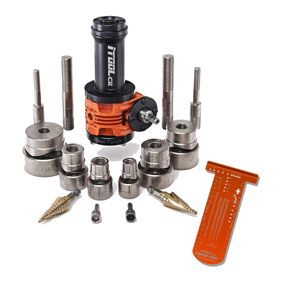
GEAR PUNCH PARTS AND ACCESSORIES All components are also sold individually. GEAR PUNCH KITS, PARTS, AND ACCESSORIES GP122 GP123 GP124 GP156 GP126 Kit Includes Kit Includes Kit Includes Kit Includes Kit Includes Gear Punch GP01 Center Point Knockout Layout Tool CP02 7/16”... - Page 11 GEAR PUNCH KITS, PARTS, AND ACCESSORIES 1” Punch and Die PD03 1-1/4” Punch and Die PD04 1-1/2” Punch and Die PD05 2” Punch and Die PD06 2-1/2” Punch and Die PD07 3” Punch and Die PD08 3-1/2” Punch and Die PD09 4”...
-
Page 12: Limited Warranty: Itoolco Gear Punch
If the part(s) is found to be defective, iTOOLco will refund freight charges paid by you in retuning the defective part(s) and prepay replacement part(s) freight charges. - Page 13 1325 CARDEN FARM DRIVE | CLINTON, TN 37716 | 865.670.3713 | ITOOLCO.COM © 2020 PROPERTY OF ITOOLCO ITOOLC0 GEAR PUNCH USER’S GUIDE 2006GP122UG P a g e | 13...
Need help?
Do you have a question about the GP122 and is the answer not in the manual?
Questions and answers