QSA Global OpenVision DX OVDX-NDT-70 Hardware Manual
X-ray system
Hide thumbs
Also See for OpenVision DX OVDX-NDT-70:
- Hardware manual (29 pages) ,
- Software manual (25 pages)
Table of Contents
Advertisement
Quick Links
Advertisement
Table of Contents

Related Manuals for QSA Global OpenVision DX OVDX-NDT-70


Summary of Contents for QSA Global OpenVision DX OVDX-NDT-70
- Page 1 OPENVISION™ OVDX-NDT-70 HARDWARE MANUAL...
-
Page 2: Table Of Contents
Heads Up Display (HUD) ..............................24 Remote Trigger and Trigger Button Options ........................27 Wi-Fi Tablet ..................................28 Imager Shield..................................28 Maintenance..................................29 Troubleshooting..................................30 QSA Global, Inc. Contact Information ........................... 32 Appendix 1: Parts List................................33 Page 2 of 33... -
Page 3: Introduction
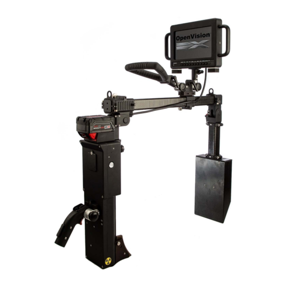
INTRODUCTION OpenVision™ DX is an easy to use, digital X-ray system with live video output for real-time radiographic inspection and reporting. A patent-pending combination of a c-arm mounted 70 kV X-ray source and a digital imager allows you to observe external defects as small as 0.010-inch (250 μm) on insulated piping. -
Page 4: Equipment Specifications
EQUIPMENT SPECIFICATIONS Table 1 OpenVision™ DX Specifications Imaging Area (Field of View) 4 in. x 6 in. (10 cm x 15 cm) Dimensions X-Ray Tube to Imager 9.5 in. (24 cm) to 20.9 in. (53 cm) Throat Depth 21 in. (58 cm) Imager Thickness 2.5 in. - Page 5 ANSI/HPS N43.5 (2005) Ionizing Radiation Regulations (2017) ISTA 3A Over the Road vibration standard MIL-STD-810, Method 514, Annex C, Cat 4 REACH/ROHS Heads Up Display (HUD) ANSI Z87.1+, US Federal OSHA US Mil Spec MIL-PRF-31013 ...
-
Page 6: Safety Precautions
SAFETY PRECAUTIONS WARNING Do not perform any unauthorized modifications to the OpenVision™ DX system or components of the system. It is important that trained and qualified personnel perform or supervise a daily safety inspection of the OpenVision DX system for obvious defects before using the system. Do not compromise on safety. Always perform the daily inspection of the system prior to use. -
Page 7: Operating Conditions
Operating Conditions OpenVision™ DX is designed for applications where the equipment will not be exposed to harsh handling or environmental extremes. See Equipment Specifications for more information X-Ray Training It is required that OpenVision DX operators are properly trained and qualified to perform radiographic inspections. This manual does not address radiographic inspection techniques or procedures. -
Page 8: Getting To Know Your Openvision™ Dx System
GETTING TO KNOW YOUR OPENVISION™ DX SYSTEM. What’s Included The OVDX-NDT-70 is shipped complete in a Pelican case. Pirate Eye Scatter Boot (optional) Spare Milwaukee Battery Wi-Fi Tablet (optional) OVDX-NDT-70 System Figure 1 OVDX-NDT As Shipped Monitor Milwaukee Battery Charger Page 8 of 33... - Page 9 Some components are packaged and placed in bags or located loose in the Pelican case. Figure 2 - OVDX AS SHIPPED MISC. COMPONENTS ITEM PART # DESCRIPTION Tablet Mounting Bracket (with optional tablet only) Monitor Sunscreen Tablet Charger (with optional tablet only) ELE114 USB-A to USB-C Adapter –...
-
Page 10: System Overview
System Overview Item Part No. Description 415100-NDT OVDX Main Housing Assembly 415200-NDT OVDX Imager Assembly 415300 OVDX C-Arm Assembly 415400 OVDX Handle Assembly 415440 OVDX Lightweight Monitor Assembly 415600 Backscatter Shield Assembly (Scatter Boot) 415200-11 Imager Cover 415530-B Remote Trigger Assembly (6ft) 415540-A Trigger Button Assembly (3 ft) HDL010... -
Page 11: Openvision™ Dx Main Housing Details
OpenVision™ DX Main Housing Details Item Part No. Description ELE054 Milwaukee ® M18™ Battery CPU Power Indicator USB Connection 313056 Controller Key HDMI Connection 1 System Status Indicator Targeting Camera Targeting Laser X-Ray Port Audio Speaker RAI002 Picatinny Rail Trigger Connection Hat Switch Image Capture / Input Button Figure 4 OpenVision DX Main Housing Assembly (Item # 415100-NDT) -
Page 12: Monitor
Monitor The OpenVision™ DX monitor (Figure 5 and Figure 6) is a lightweight 7-inch HDMI display. It can be connected to either of the two HDMI ports provided on the OpenVision DX via the HDMI cable provided. The monitor comes configured to work with your OpenVision DX system. -
Page 13: Trigger Assemblies
Trigger Assemblies The OVDX-NDT-70 comes standard with two trigger assembles: 415540-A (Figure 8) can be used for X-ray firing only. 415530-B (Figure 9) can be used for X-ray firing and Image / Video capture. Refer to Figure 10 for the connection location. -
Page 14: Principles Of Operation
PRINCIPLES OF OPERATION Radiography uses X-rays or gamma rays passing through a specimen onto an imaging medium (film, digital imager, imaging plate, etc.) on the opposite side. The quality and quantity of radiation reaching the imaging medium is largely determined by the object’s thickness and density. -
Page 15: Radiation Zones
Output Radiation Levels OpenVision™ DX radiation levels vary depending on kV/mA settings. QSA Global, Inc performs testing at maximum power at the highest kV setting (70 kV, 0.17 mA) to verify collimation and image quality. Operators must be aware of safe boundary distances while using the OpenVision DX. -
Page 16: Backscatter Radiation Levels
Backscatter Radiation Levels Survey Without Backscatter Shield With Backscatter Shield Point mR/Hr (µSv/hr) in mR/Hr (µSv/hr) 2.5 (25) 1(10) 7(70) 5(50) 5.5 (55) 1.5 (15) 1 (10) 0 (0) 6 (60) 1.5 (15) 6.5 (65) 5 (50) ≤Background (BKGD) ≤BKGD ≤BKGD ≤BKGD ≤BKGD... -
Page 17: Backscatter
Backscatter Backscatter occurs when X-rays interact with material (piping, insulation, etc.), potentially travelling in undesirable directions (e.g. towards the operator). Backscatter is dependent on many variables including geometry, material, and energy level. It can potentially increase the dose to the operator’s extremities. The best way to minimize backscatter is to use the lowest kV / mA combination to achieve acceptable images. - Page 18 Figure 14 Example of Backscatter Figure 15 OpenVision DX with backscatter shield properly positioned against insulation sheathing. Page 18 of 33...
-
Page 19: Operation
OPERATION WARNING When the System Status Indicators turn AMBER (see Figure 4), ionizing radiation is being produced. If you wish to perform extended operations with the OpenVision DX system, ensure that ambient temperatures are below 120 °F (49 °C) and above -20 °F (-29 °C). Quick Setup / Scanning Your OpenVision™... - Page 20 Repeat action for imager housing: Red Button Figure 17 Unlock Imager Housing Position handles, attach and position pistol Grip and monitor mount as desired: D-Handle Monitor Mount Pistol Grip Figure 18 - Handle Adjustments Page 20 of 33...
- Page 21 The OpenVision DX utilizes standard picatinny rails and allows the handles and grips to be configured in multiple ways to suit different applications (Figure 19) shows one such configuration. The grip is moved to the top tube and the D-handle is moved to the main housing. Figure 19 - Optional Handle Configuration Example ...
- Page 22 Turn monitor ON (located on upper-right corner of monitor). Monitor Power Button Figure 21 Monitor Power Button Install Trigger Switch by pushing up and twisting until it locks into place. Trigger Switch Connection Figure 22 Trigger Switch Connection Page 22 of 33...
- Page 23 Install controller key and turn to ON and allow time for system to initialize. System status indicators (located on either side of main housing) will turn GREEN when system is ready. CPU Power Indicator Controller Key (ON) System Status Indicator Figure 23 Indicators and Power Switch Details ...
-
Page 24: Accessories
ACCESSORIES Heads Up Display (HUD) This accessory (Item #415140) allows for an alternative to a display mounted directly to the OpenVision DX system. HUD specifications: Ballistic Protection Standards: U.S. MIL SPEC MIL-PRF-31013 ANSI Z87.1+ U.S. Federal OSHA ... - Page 25 To make slight adjustments to the focus, adjust the diopter to the left or right using your index finger. Figure 25 Diopter adjustment The standard configuration provides the image to your right eye. Clear or tinted lenses can be used based on external lighting conditions: Figure 26 Example image output for HUD Page 25 of 33...
- Page 26 Micro-USB charging port * Video input Output to heads-up-display HDMI input Power Reduce brightness Increase brightness Toggle aspect ratio (4:3 / 16:9) ** Toggle color / black and white The HUD controller must be charged separately with a USB charger. It is not powered by the OpenVision DX system.
-
Page 27: Remote Trigger And Trigger Button Options
Remote Trigger and Trigger Button Options The OVDX-NDT-70 comes standard with 415530-B Remote Trigger Harness (6 ft length) and 415540-A Trigger Button Harness (3 ft length). Optional lengths of each can be ordered. Remote Trigger Harness 3 ft length - 415530-A (Figure 28) Figure 28 - 415530-A Remote Button Harness 6 ft length - 415540-B (Figure 29) Figure 29 - 415540-B... -
Page 28: Wi-Fi Tablet
Wi-Fi Tablet The Wi-Fi Tablet assembly (Figure 30, Item # 415430) is an optional accessory which allows for wireless transmission. It can be mounted to the OpenVision™ DX handle assembly or be used as a hand-held tablet. See the software user manual (MAN-063) for operation instructions. -
Page 29: Maintenance
MAINTENANCE The OpenVision™ DX has been designed to require minimal maintenance by the operator. QSA Global, Inc. recommends daily visual inspection of the system. Specific attention should be paid to the following: M18™ battery and its mount (on top of Main Housing) – Ensure both are clean, and in sound shape. -
Page 30: Troubleshooting
CAUTION Opening the OpenVision DX potentially will damage the system and will void any warranty. If faced with any issues with the OpenVision DX, contact your QSA Global, Inc. representative immediately for guidance. The OpenVision™ DX has been designed as a rugged, safe, reliable system. A series of interlocks and self-checks are built into the system to ensure safe operation. - Page 31 Error Code Cause Description Camera Communication Communication error with internal camera. Cycle system Error power to clear error. Camera Communication Communication error with internal camera. Cycle system Error power to clear error. Page 31 of 33...
-
Page 32: Qsa Global, Inc. Contact Information
APPENDIX 1: PARTS LIST Part # Description OVDX-NDT-70 OpenVision™ DX System, Complete 415400 OVDX Handle Assembly 415440 OVDX Lightweight Monitor Assembly 415600 OVDX Backscatter Shield Assembly ELE088 HDMI Cable ELE054 Milwaukee M18™ Battery ® 313056 Controller Key 415140 Pirate Eye Head Mount Display 415230 Imager Shield Assembly 415430...
Need help?
Do you have a question about the OpenVision DX OVDX-NDT-70 and is the answer not in the manual?
Questions and answers