Table of Contents
Advertisement
Quick Links
Installation & Operation Manual
SENS Part Number:
Document Revision:
DCN Number:
Date:
PATENTED US 9,270,140; 9,385,556; 9,413,186; 9,509,164;
9,466,995; 9,948,125; 10,575,433
Installation or service questions?
Call SENS between 8 a.m. and 5 p.m. (Mountain Time),
Monday through Friday, or visit our website.
Copyright © Stored Energy Systems LLC 2020
The SENS name / logo, EnerGenius, HELIX, and Dynamic Boost are trademarks of Stored Energy Systems LLC
CABINET
Automatic Battery Charger/Power Supply
101336
A
107839
May 4, 2020
SENS EnerGenius® DC Cabinet Technical Manual
1
1840 Industrial Circle
Longmont, CO 80501
Phone: 303.678.7500
800.742.2326
Fax:
303.678.7504
Email:
service@sens-usa.com
Web:
www.sens-usa.com
Advertisement
Table of Contents
Troubleshooting

Subscribe to Our Youtube Channel
Related Manuals for Sens EnerGenius DC Cabinet


Summary of Contents for Sens EnerGenius DC Cabinet
- Page 1 Call SENS between 8 a.m. and 5 p.m. (Mountain Time), Web: www.sens-usa.com Monday through Friday, or visit our website. Copyright © Stored Energy Systems LLC 2020 The SENS name / logo, EnerGenius, HELIX, and Dynamic Boost are trademarks of Stored Energy Systems LLC...
-
Page 2: Table Of Contents
Shunt Trip AC Breaker - optional ......................36 9.9. Restore Factory Defaults .......................... 36 9.10. Keypad Operation ............................ 36 9.11. Configuration with SENS Setup Utility ..................... 41 9.12. Temperature Compensation ........................41 9.13. Load Share Charger Operation ......................... 42 9.14. - Page 3 SENS EnerGenius® DC Cabinet Technical Manual MODBUS COMMUNICATIONS .......................... 45 11.1. TCP/IP Modbus—Optional ........................45 11.2. Modbus RS-485—Optional ........................45 11.3. Modbus Holding Registers ........................45 11.4. Basic Charging Alarms Bit Definition ......................47 11.5. Charging Status Bit Definition ........................48 11.6.
-
Page 4: Important Safety Instructions For Installer And Operator
SENS EnerGenius® DC Cabinet Technical Manual IMPORTANT SAFETY INSTRUCTIONS FOR INSTALLER AND OPERATOR 1.1. SAVE THESE INSTRUCTIONS – This manual contains important safety and operating instructions for EnerGenius® DC Cabinet battery chargers. 1.2. Before using battery charger, read all instructions and cautionary markings on battery charger, battery, and product using battery. - Page 5 1.10.8. When charging batteries, charge LEAD-ACID or LIQUID ELECTROLYTE NICKEL-CADMIUM batteries only. Consult SENS before using with any other type of battery - other batteries may burst and cause injuries to persons and damage to property. NEVER charge a frozen battery.
-
Page 6: Model Number Breakout
SENS EnerGenius® DC Cabinet Technical Manual MODEL NUMBER BREAKOUT Parameter Code Value Product Family EnerGenius DC Enclosure Type Cabinet AC Input Voltage Three Phase - 480VAC AC Interrupt Standard Interrupt Rating (25kAIC) High Interrupt Rating (65kAIC) DC Output Voltage 120 VDC... -
Page 7: Performance Specifications
SENS EnerGenius® DC Cabinet Technical Manual PERFORMANCE SPECIFICATIONS EnerGenius DC high power industrial/utility class 3-phase battery charger/power supply, specially hardened for use in harsh industrial environments. Advanced technology switch mode power conversion is significantly smaller & lighter than conventional line frequency (e.g. SCR) power conversion and, even without a battery connected, delivers lower output ripple and much faster dynamic response. - Page 8 Local computer Change all parameters, troubleshoot, create/save configuration files for quick download to chargers using network connection and SENS Setup Utility software available at www.sens-usa.com Status reporting LEDs Two multi-color front panel status LEDs Metering DC Voltmeter accurate to ±2%;...
- Page 9 SENS EnerGenius® DC Cabinet Technical Manual Alarm Inputs Two optional input contacts (via optional battery monitor) to monitor status of, and modify charger operation based on, external devices such as battery room fan or hydrogen monitor. Alarm Form C contacts Nine Form C contacts, rated 30V, 2A resistive, assignable.
-
Page 10: System Overview
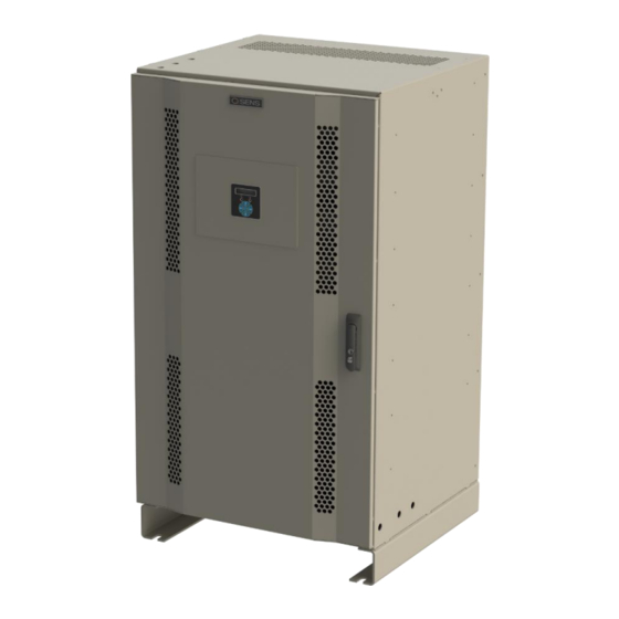
Modbus: RJ-45 or terminal blocks 28 to 16 AWG. Form C connections alarms: 28 to 16 AWG. Power connections AC breaker: 14 – 1/0AWG DC breaker: ≤200A: 1AWG – 350kcmil. >200A: two 2/0AWG – 600kcmil. SYSTEM OVERVIEW 4.1. Physical Overview Figure 1 – EnerGenius DC Cabinet Overview... -
Page 11: Functional Overview
Some of the available configuration options may not be applicable to a given installation. Adjustments to settings can be made via the front panel keypad or the SENS Setup Utility software via ethernet connection of the EnerGenius DC Cabinet unit to a computer. - Page 12 RS-485) and IEC 601850 4.2.4. Module Redundancy The EnerGenius DC Cabinet can be factory ordered with N+1 or N+2 module redundancy. This provides more power modules than are required to meet the rated output. All modules will actively share the load up to the rated current of the cabinet. Should a power module fail, each remaining module will equally share the connected system load and battery recharge demand.
-
Page 13: Mounting Instructions
A, B, C, or D. Multiple units can be assigned to a common load or units can be allocated to separate outputs for multiple unique loads. All of the channelized EnerGenius DC Cabinet units on a common communication bus can be controlled / monitored from a single point. -
Page 14: Setup And Wiring
IMPORTANT! The charger is configured at the factory and typically requires no adjustments before operating. Refer to the label on the breaker panel cover for factory configured output and alarm relay assignments. The charger may be reconfigured using the front panel keypad or by software programming using the SENS Setup Utility. - Page 15 SENS EnerGenius® DC Cabinet Technical Manual appropriate output conductor gauge and length. Use of a remote temperature sensor (see section 9.12) is highly recommended for best charging performance. Table 2 – DC Output Cable Size Charger Maximum Charger Rated Resistance...
-
Page 16: Grounding Instructions And Connection
SENS EnerGenius® DC Cabinet Technical Manual 152.0 0.037 203.0 0.028 253.0 0.022 The above lengths consider the resistance of the battery and cables only and do not take into account any additional interconnects. The above lengths factor in a maximum voltage drop of 2% of the nominal voltage. -
Page 17: Ac Connection
SENS EnerGenius® DC Cabinet Technical Manual Table 5 – DC Output Breaker Rating Charger Nominal DC Output DC Breaker Rating DC Breaker Interrupt DC Breaker Interrupt Output Voltage Capacity (Amps) (Amps) Standard Rating Optional Rating (VDC) (KAIC) (KAIC) 6.4. AC Connection This unit is to be permanently connected to the AC circuit and to the battery. -
Page 18: Standard Alarm Connections
See charger breaker panel label for original factory alarm relay assignments (see Figure 2). Alarm relay assignments are custom configurable using the front panel keypad (based on application) or the SENS Setup Utility. Connect alarm wiring to the respective terminals on the pluggable terminal block in the charger (see Figures 1 for location in charger and Figure 7 for detail). -
Page 19: Optional Pilot Relay Connections
Optional Pilot relay assignments are custom configurable using the front panel keypad (based on application) or the SENS Setup Utility. Connect optional alarm wiring to the respective terminals on the pluggable terminal block in the charger (see Figure 1 for location in charger and Figure 8 for detail). To make wiring easier, the terminal block unplugs from the header. - Page 20 SENS EnerGenius® DC Cabinet Technical Manual Figure 8 – Optional Pilot RelayConnections (TB1 - pins 1-6 shown) 2 RELAYS, PULL TO REMOVE 3 POSITIONS PER RELAY: FROM HEADER COM, OK, FAIL Table 9 – Optional Pilot Relay Connections Wire from COM to OK for alarm present on open circuit or from COM to FAIL for present on closed circuit.
-
Page 21: Canbus Connections
No connect pass-through Power* Common (isolated) *Main circuit PCA only, used for interconnect between SENS devices 6.8. Modbus Connections - Optional Every charger includes RS-485 connections via a 4-pin pluggable terminal block (see Figure 10). This interface is intended for monitoring and communicating with the charger. Available protocols include Modbus and DNP3. -
Page 22: Ethernet
The charger is not equipped with terminators. Termination may be provided as part of the network cabling or 120-ohm termination plugs for the RJ-45 communications connector on the charger are available to order separately (SENS 803707). Figure 11 – Modbus Termination LT = Line Termination 120-ohm resistor 6.9. -
Page 23: Verify Connections
Control / Communications Panel (see Figures 1 and 13). The only optional hardware required is a Cat5 or better RJ-45 network cable available either from SENS or local computer supply. Use of this sharing cable is essential to synchronizing operation of the Dynamic Boost and HELIX modes and helps ensure that current is shared within +10% between chargers. -
Page 24: Start-Up Procedure
Refer to the label on the breaker panel for factory configured output voltage, battery type and configuration code (see Figure 2). Review and adjust charger configuration using the front panel keypad or the SENS Setup Utility if factory configured settings require modification. See section 9.10 additional details on keypad navigation. -
Page 25: Apply Ac Input Voltage
SENS EnerGenius® DC Cabinet Technical Manual 7.2.3.4. Power Supply (PSP) This configuration code is intended for standard power supply applications where a storage battery is not connected. 7.3. Apply AC Input Voltage Verify the AC input is the correct value (188-528 VAC, 47-63 Hz) and apply AC to charger. -
Page 26: Alarms, Leds And Display
SENS Setup Utility. By default, the relay contacts change state 30 seconds after the onset of a fault. The relay delay is configurable using the front panel keypad (see section 9.10) or the SENS Setup Utility. See section... -
Page 27: Lcd Panel
Indicates DC output voltage is above the High DC Voltage factory alarm setpoint (see Table 12) or the configured level if setpoint is adjusted using keypad or SENS Setup Utility. Activates solid yellow DC LED. When this alarm is assigned to a relay contact HIGH DC VOLTAGE will cause the assigned relay to change to the Failed state after the time delay. - Page 28 Voltage factory alarm setpoint (see Table 13) or the configured level if setpoint is adjusted using keypad or SENS Setup Utility. The BATTERY DISCHARGING alarm is the first to trigger of three low output voltage alarms and is followed by LOW DC and then END OF DISCHARGE. Alarm setpoint must be set higher than LOW DC and END OF DISCHARGE alarms.
- Page 29 Indicates DC output voltage is below Battery End Discharge factory alarm setpoint (see Table 15) or the configured level if setpoint is adjusted using keypad or SENS Setup Utility. This alarm is intended only for longer discharge rates (i.e. not engine starting applications) and indicates the normal end-of-discharge voltage for a lead-acid battery.
- Page 30 SENS EnerGenius® DC Cabinet Technical Manual VRLA 2.530 2.568 2.833 VRLA 2.530 2.568 2.833 2.200 *Configuration Code displayed on charger label. 8.4.8. Reverse Polarity Indicates battery is connected backwards. Charger output is disabled until the condition is corrected. Activates flashing red/yellow DC LED. When this alarm is assigned to a relay contact REVERSE POLARITY will cause the assigned relay to change to the Failed state after the time delay.
- Page 31 Indicates battery voltage is below the Startup Voltage setpoint or the configured level if setpoint is adjusted using keypad or SENS Setup Utility. When this alarm is assigned to a relay contact DC BELOW STARTUP VOLTAGE will cause the assigned relay to change to the Failed state after the time delay.
- Page 32 SENS EnerGenius® DC Cabinet Technical Manual 8.4.23. Check Filter Indicates charger has experienced a thermal roll back which might be caused by a clogged input air filter. Check module input air filter and clean if needed. When this alarm is assigned to a relay contact CHECK FILTER will cause the assigned relay to change to the Failed state after the time delay.
-
Page 33: Operation
SENS EnerGenius® DC Cabinet Technical Manual 8.4.33. AC Voltage High Indicates AC Voltage is above the AC Max Voltage alarm setpoint. When this alarm is assigned to a relay contact AC VOLTAGE HIGH will cause the assigned relay to change to the Failed state after the time delay. -
Page 34: Float Mode
Dynamic Boost can be enabled or disabled by the user at any time. Configure the charger appropriately using the keypad or SENS Setup Utility. Use of the optional remote temperature compensation probe is highly recommended to maximize charging performance and optimize battery life. -
Page 35: Helix Mode
AC and DC power to reset the charger and resume charging. This safety feature can be temporarily defeated from the keypad or the SENS Setup Utility in order to charge/commission a zero-volt or fully discharged battery. To initiate the defeat system, navigate to the BATTERY SET UP menu to set the desired minimum startup voltage level. -
Page 36: Shunt Trip Ac Breaker - Optional
Ground Fault Trip Point 9.10. Keypad Operation The front panel keypad provides the ability to adjust charger settings without the SENS Setup Utility. 9.10.1. Security Code Protection Chargers may be security code protected to ensure only authorized personnel may adjust charger settings. - Page 37 SENS EnerGenius® DC Cabinet Technical Manual Table 20 – Menu Navigation or for main fields Step 1 or for details within each main field Step 2 or to adjust values Step 3 to return to main fields Step 4 ...
- Page 38 SENS EnerGenius® DC Cabinet Technical Manual Output Settings Float Voltage Adjust output Float voltage, must be greater than 60% of Boost setting Boost Voltage Adjust output Boost voltage from, must be same or greater than Float setting, must not be greater than 166% of Float...
- Page 39 SENS EnerGenius® DC Cabinet Technical Manual Battery Set-up Battery Select (type) Select type of battery to be charged - flooded lead-acid, AGM, nickel-cadmium VRLA, power supply. Battery Select (cells) Adjust number of series cells in battery string Batt Commission (voltage)
- Page 40 SENS EnerGenius® DC Cabinet Technical Manual Display Test Press UP arrow to set all LCD segments black and DOWN arrow to clear all LCD segments UI Access Control Select allowed user interface access. Access options include read-only viewing, normal access or full access adjustments for advanced users.
-
Page 41: Configuration With Sens Setup Utility
Temperature compensation is disabled by using the keypad or by setting the temperature compensation slope to zero using the SENS Setup Utility. The temperature present at a sensor (local or remote) is displayed on the front panel LCD. Actual battery temperature is only displayed if the optional remote temperature sensor is connected to the charger and placed at the batteries. -
Page 42: Load Share Charger Operation
SENS EnerGenius® DC Cabinet Technical Manual 9.13. Load Share Charger Operation Multiple chargers may be connected in parallel to provide charger redundancy and increased charging current. Load sharing chargers are fault tolerant; one charger failure will not cause failures in paralleled chargers. -
Page 43: Efficiency
Ensure that air filter is clean and free from debris (see section 10.3). 10.2. Power Module Access The EnerGenius DC Cabinet is powered by up to eight EnerGenius DC power modules. To remove a module first unlock the module by moving the cam latch to the unlock position. Then pull the module out to remove. -
Page 44: Air Filter
If the charger was ordered with the optional supplemental surge protection (see Figure 1), these devices may be need be replaced if operated under extensive surge conditions. Should the device need to be replaced indication will be provided on the LEDs, display, and alarms. Contact SENS for replacement components and detailed service instructions. -
Page 45: Modbus Communications
11.2. Modbus RS-485—Optional Serial Modbus communications over RS-485 using RTU or ASCII mode are optional. Modbus communications settings may be configured using the keypad or SENS Setup Utility prior to executing communications. Modbus is provided over RS-485 using RTU or ASCII mode. - Page 46 SENS EnerGenius® DC Cabinet Technical Manual 0x00C 0x00D Model Num 1_4 Model number character 0x00E 0x00F Model Num 5_8 Model number character 0x010 0x011 Model Num 9_12 Model number character 0x012 0x013 Model Num 13_16 Model number character 0x014 0x015...
-
Page 47: Basic Charging Alarms Bit Definition
SENS EnerGenius® DC Cabinet Technical Manual 0x0EE 0x0EF Unit Line Current 2 AC Line 2 Current 32768 0x0F0 0x0F1 Unit Line Voltage 3 AC Line 3 Voltage 32768 0x0F2 0x0F3 Unit Line Current 3 AC Line 3 Current 32768 Timer for elapsed time with a given... -
Page 48: Charging Status Bit Definition
SENS EnerGenius® DC Cabinet Technical Manual Battery On Battery is beginning to discharge and DC output voltage is below Batt 0x13 Discharge Discharge Voltage alarm setpoint. Battery End 0x14 DC output voltage is below Batt End Discharge Voltage alarm setpoint. -
Page 49: Charging Ac Alarms Bit Definition
SENS EnerGenius® DC Cabinet Technical Manual Battery temperature is above the High Battery 0x02 High Battery Temperature Temperature alarm setpoint. Battery temperature is high enough that the unit has High Battery Temperature shut off for safety precautions. Only available when a... -
Page 50: Accessory Assigned Channel Alarms Bit Definition
SENS EnerGenius® DC Cabinet Technical Manual The AC breaker is OPEN or has tripped. Only available with Breaker 0x02 AC1 Breaker Status option. 0x03 Unused Unused 0x04 Unused Unused The DC supplementary surge protector has expired and needs 0x05 DC SPD replacement. -
Page 51: Troubleshooting/Error Codes
SENS EnerGenius® DC Cabinet Technical Manual 12 TROUBLESHOOTING/ERROR CODES 12.1. Configuration Error Codes Error codes are displayed on front panel LCD. Error Scope Description Corrective Action Charger Invalid output channel. Chargers must - If necessary, enable the channel using the... - Page 52 SENS EnerGenius® DC Cabinet Technical Manual Channel Too few chargers operating. The - Use the "Set DC Output" setting in the combined output rating of all chargers "Other Settings" menu or the setup utility to operating on this channel is less than the verify all chargers' output channel settings.
- Page 53 SENS EnerGenius® DC Cabinet Technical Manual to select the Battery Type, Float Voltage, and Range for your battery. Unit (or Missing chargers. A charger that should - Check for a charger that has failed System) be present is missing, has failed, or (indicated by its LED status).
-
Page 54: Troubleshooting Guide
SENS EnerGenius® DC Cabinet Technical Manual 12.2. Troubleshooting Guide AC LED DC LED Fan / Symptom Possible Causes Recommended Actions Filter Display 1. Main control 1. Using a voltmeter, check that accessory AC board to accessory AC input voltage and frequency at... - Page 55 SENS EnerGenius® DC Cabinet Technical Manual charger AC input and DC output voltage as required. 2. If step 1 doesn’t resolve issue, remove both AC and DC power for 1 minute, then reapply power. 3. If steps 1 and 2 don’t resolve issue, main control board may need to be replaced.
- Page 56 SENS EnerGenius® DC Cabinet Technical Manual *SOLID SOLID AC good, high 1. Alarm setpoint 1. Check that charger battery GREEN YELLOW battery voltage incorrect for settings and alarms are set application appropriately for the application 2. DC voltage is high and battery under charge.
- Page 57 SENS EnerGenius® DC Cabinet Technical Manual *SOLID DOUBLE AC good, output 1. Negative DC 1. Check that the negative DC GREEN FLASH disabled connection is broken connection is made and that to one of the connection is tight. chargers 2. If step 1 doesn’t resolve issue, 2.
- Page 58 SENS EnerGenius® DC Cabinet Technical Manual / load voltage (consider battery surface charge, alternator, and any connected equipment). SOLID SOLID AC fail, low 1. Proper AC voltages AC LED YELLOW battery voltage or frequency not 1. Using a voltmeter, check that...
- Page 59 SENS EnerGenius® DC Cabinet Technical Manual RED AC light, a charger module failure is the likely cause. Replace module. DC LED 1. Remove AC and DC power from charger for 1 minute before reapplying power. Ensure AC voltage and/or DC voltage is within specified operating limits of the charge.
- Page 60 SENS EnerGenius® DC Cabinet Technical Manual or setup utility is not available, replace charger ALTERNATING Starting-up 1. Charger is still 1. Remove both AC and DC power FLASHING GREEN powering-on for 1 minute and then reapply 2. Failed display power. Allow charger at least 1 board minute to fully boot.
-
Page 61: Glossary
SENS EnerGenius® DC Cabinet Technical Manual 13 GLOSSARY Original Factory Configuration Configuration set at the factory. Charger operates using settings configured at the factory per customer order. See configuration details on breaker panel label. Float Voltage Float output voltage is used to maintain batteries in a fully charged state and prevents a fully charged battery from becoming overcharged. - Page 64 L2 / N GROUND L2 / N GROUND DISPLAY POWER VIDEO DISPLAY USB 1 USB 2 SERVICE ETHERNET ETHERNET SENSBUS SENSBUS SENSBUS MODBUS - A MODBUS - B RS485 MODBUS - COMMON SHIELD MODBUS - SHIELD FAIL K01 - FAIL K01 - OK K01 - COMMON FAIL...
- Page 65 L2 / N GROUND L2 / N GROUND DISPLAY POWER VIDEO DISPLAY USB 1 USB 2 SERVICE ETHERNET ETHERNET SENSBUS SENSBUS SENSBUS MODBUS - A MODBUS - B RS485 MODBUS - COMMON SHIELD MODBUS - SHIELD FAIL K01 - FAIL K01 - OK K01 - COMMON FAIL...
- Page 66 L2 / N L2 / N GROUND GROUND L2 / N L2 / N GROUND GROUND DISPLAY POWER DISPLAY POWER VIDEO VIDEO DISPLAY DISPLAY USB 1 USB 1 USB 2 USB 2 SERVICE SERVICE ETHERNET ETHERNET ETHERNET ETHERNET SENSBUS SENSBUS SENSBUS SENSBUS MODBUS - A...
- Page 67 Directives(s) and Standard(s). ________________________________________ _April 28, 2020_______ Sam Coleman Date Compliance Manager Stored Energy Systems, LLC STORED ENERGY SYSTEMS, LLC 1840 INDUSTRIAL CIRCLE, LONGMONT, COLORADO 80501 FAX 303.678.7504 303.678.7500 www.sens-usa.com email: info@sens-usa.com FORM-319 REV A DATE ISSUED: 4/28/2020...
- Page 68 Return Material Authorization (RMA) number provided by SENS. If, in SENS’ opinion, the problem can be rectified in the field, SENS may elect to ship replacement parts for customer installation instead of having the product returned to the factory.
Need help?
Do you have a question about the EnerGenius DC Cabinet and is the answer not in the manual?
Questions and answers