
Related Manuals for IBA ibaPADU-8-O


Summary of Contents for IBA ibaPADU-8-O
- Page 1 Parallel-Analog-Digital-Converter for Analog and Digital Outputs Manual Issue 1.9...
- Page 2 Required corrections are contained in the following regulations or can be downloaded on the Internet. The current version is available for download on our web site http://www.iba-ag.com. Protection note Windows® is a label and registered trademark of the Microsoft Corporation. Other pro- duct and company names mentioned in this manual can be labels or registered trade- marks of the corresponding owners.
-
Page 3: Table Of Contents
Mode 2-impulse generator for binary output #0 ..........14 System topologies ..................16 Single daisy-chain with ibaPADU-8-O............. 16 Multiple daisy-chains with ibaPADU-8-O............16 Daisy-chain with ibaPADU-8-O to ibaLink-SM-64-io ........17 Process IO redundancy .................. 17 Working with ibaPADU-8-O and ibaLogic V3 ..........18 Hardware ......................18 Software Application.................. - Page 4 Manual ibaPADU-8-O Working with ibaPADU-8-O and ibaLogic V4 ..........20 10.1 Hardware......................20 10.2 Software Application..................20 Technical data....................23 11.1 Main data ......................23 11.2 Analog outputs ....................23 11.3 Digital outputs ....................24 11.4 Dimensional drawing..................25 Support and Contact..................26...
-
Page 5: About This Manual
Manual About this manual This manual describes in detail the configuration and use of the device ibaPADU-8-O. It serves both as a tutorial and a reference document. Target group This manual addresses in particular the qualified professionals who are familiar with handling electrical and electronic modules as well as communication and measurement technology. -
Page 6: Used Symbols
Manual ibaPADU-8-O Used symbols If safety instructions or other notes are used in this manual, they mean: The non-observance of this safety information may result in an imminent risk of death or severe injury: By an electric shock! ... -
Page 7: Introduction
Manual Introduction The ibaPADU-8-O device (Parallel analog digital unit 8 Outputs) serves as analog and digital output for purposes of process automation or to generate output stimuli for plant simulators. The sender normally is an ibaFOB output card, e. g. ibaFOB-2io-D or iba- FOB-4i-D + ibaFOB-4o-D. -
Page 8: System Requirements
Manual ibaPADU-8-O System requirements ibaLogic Soft PLC system, running on a computer equipped with ibaFOB output card(s) ibaPDA-V6 system, running on a computer equipped with ibaFOB output card(s) PLC and control systems, with ibaLink-SM-64-io or ibaLink-SM-128V-i-2o board ... -
Page 9: Product Properties
The ibaLink-SM-64-io and ibaLink-SM-128V-i-2o boards are also designed to work with up to 8 ibaPADU-8-O devices in a chain over 1 FO-link. They offer one, respectively 2 fiber optic ports for connecting ibaPADU-8-O chains. This gives a new ability especially when revamping older systems, because only 1 slot is needed to add 64 A + 64 D out- put signals, respectively 128 A + 128 D outputs. -
Page 10: Device Views, Connectors And Switches
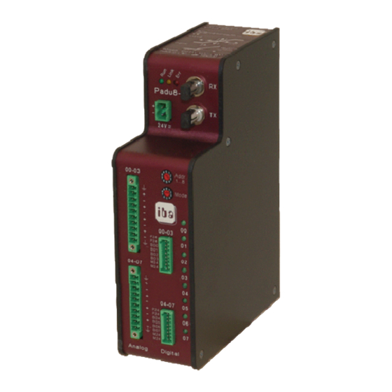
Manual ibaPADU-8-O Device views, connectors and switches Front side Top side Serial number and email-support address Device status LEDs 24 V power supply (X14) Fiber optic input (X11) Fiber optic output (X10) Address switch S1 (1..8) Mode switch S2 (Run = 0) Analog outputs 00..03 (X1) -
Page 11: Power Supply Input X14
Manual 6.5.1 Power supply input X14 The 2-pole connector serves as power supply input. A non-stabilized DC power supply (with a voltage range between 18 V and 32 V) may be connected. 6.5.2 Fiber optic connectors TX (X10) and RX (X11) The 2 fiber optic jacks (ST types) are used to connect to fiber optic communication links. -
Page 12: Connector Pin Outs X14, X1, X2, X5, X6
Manual ibaPADU-8-O 6.5.5 Connector pin outs X14, X1, X2, X5, X6 Note The counting order is always top down starting on top with #1. Power supply X14 Connection +24 V Analog outputs X1 and X2 Signal (X1) Signal (X2) Shield... -
Page 13: Status Leds
To reduce unwanted electromagnetic interference, it is required to use shielded IO ca- bling and connect the shield one time at the ibaPADU-8-O side with the connector X9. The DIN-rail must be always earthed to provide a good shielding quality. -
Page 14: Selecting The Mode Of Operation
Rising edges within an active pulse sequence are ignored! After processing a pulse the ibaPADU-8-O needs a recovery time (TREC) of at least 400 s. If an event occurs within this period the execution is performed in the next cy- cle (= 1 ms later). - Page 15 Ana Out #0 DLY = 0 Pulse Control Legend: System transport delay time (not constant!) until data arrival at iba- PADU-8-O device (<=1 ms) Programmed impulse pre-delay (D0…D7 of Ana Out #0) Programmed pulse length (D8…D15 of Ana Out #0 Ecovery time of ibaPADU-8-O >= 40 0s...
-
Page 16: System Topologies
Figure 3: Single daisy-chain with ibaPADU-8-O Multiple daisy-chains with ibaPADU-8-O ibaPADU-8-O devices used as process outputs with an ibaFOB-4o (without ibaPADU-8 input devices). Figure 4: Multiple daisy-chains with ibaPADU-8-O Issue 1.9... -
Page 17: Daisy-Chain With Ibapadu-8-O To Ibalink-Sm-64-Io
Manual Daisy-chain with ibaPADU-8-O to ibaLink-SM-64-io ibaPADU-8-O devices used as process outputs for a PLC S5 or MMC216 with an ibaLink-SM-64-io board(with ibaPADU-8 input devices). Figure 5: Daisy-chain with ibaPADU-8-O to ibaLink-SM-64-io Process IO redundancy With the ibaBM-FOX-i-3o device, optical data streams (fibers) may be multiplied. This is possible at every location within an input or output chain of ibaPADU devices, that means between ibaPADU-8-O devices also. -
Page 18: Working With Ibapadu-8-O And Ibalogic V3
Working with ibaPADU-8-O and ibaLogic V3 Hardware The ibaPADU-8-O must be connected to an ibaFOB-card with output capability, i. e. ibaFOB-2io-S or ibaFOB-4i-S/-4o. The ibaFOB transmits the ibaLogic V3 output image with an update rate of 1 ms to the output devices. - Page 19 ID = 0. The following example shows the wiring to activate the analog output channels 1 and 2 of ibaPADU-8-O #1, and the analog output channel 4 of device #2 (ibaFOB IO/O M1 Ana12). The activated binary output is output 1 of device #5 connected with output 2 of ibaFOB IO-card with the ID = 1.
-
Page 20: Working With Ibapadu-8-O And Ibalogic V4
Each of the 3.3 Mbit/s output links of an ibaFOB card transmits up to 64 analog and 64 digital signals. A daisy-chain consisting of up to 8 ibaPADU-8-O devices can be con- nected to each link. The mapping of signals is determined by the device address 1...8. - Page 21 Manual Click on the “Assign Signals” tab, drag the correct group of outputs from the left pane towards the branch “Outputs” of the tree in the right pane and let it drop. In the dialog which opens automatically you can enter a group name if you want.
- Page 22 Manual ibaPADU-8-O In the program designer the sample application of chapter 9.2 would look like as fol- lows: Issue 1.9...
-
Page 23: Technical Data
Manual Technical data 11.1 Main data Order no. iba AG 10.120800 Mechanical stability DIN IEC 68-2-6 (if DIN rail is mounted correctly) Operating temperature 32 °F to 122 °F (0 C to 50 Storage temperature -13 °F to 158 °F (-25... -
Page 24: Digital Outputs
Manual ibaPADU-8-O 11.3 Digital outputs Amount Output signal log 0; 0 V Load power supply external DC 24 V log 1; + 24 V Save state is log „0“ Output current/output 100 mA (typ.) At 24 V and switching frequency 1000 Hz 250 mA (max.) -
Page 25: Dimensional Drawing
Manual 11.4 Dimensional drawing (Dimensions given in mm) Figure 8: Dimension drawing Issue 1.9... -
Page 26: Support And Contact
Koenigswarterstr. 44 90762 Fuerth Germany Phone: +49 911 97282-0 Fax: +49 911 97282-33 E-Mail: iba@iba-ag.com Contact: Mr. Harald Opel Regional and Worldwide For contact data of your regional iba office or representative please refer to our web site www.iba-ag.com. Issue 1.9...
Need help?
Do you have a question about the ibaPADU-8-O and is the answer not in the manual?
Questions and answers