
Subscribe to Our Youtube Channel
Related Manuals for Silverline SCV 1160-50 RF HERMOD


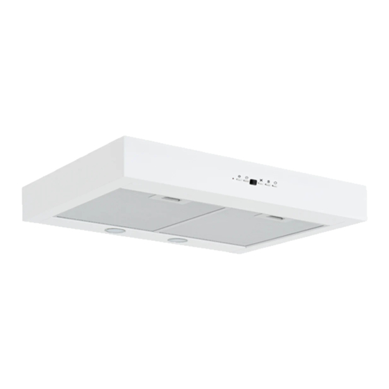
Summary of Contents for Silverline SCV 1160-50 RF HERMOD
- Page 1 Assembly instructions SCV 1160-50 RF HERMOD SCV 1160-50 HV HERMOD SCV 1160-70 RF HERMOD SCV 1160-70 HV HERMOD Read this manual carefully before installation / commissioning...
- Page 2 MANUFACTURER Merzifon OSB AMASYA, Silverline IMPORT Jilmas Group Nordic ApS Eli Christensens Vej 90, 7430 Ikast Denmark Telephone: +45 70104014 Fax: +45 70131389 Internet: www.silverline.dk 1, en_US 24.07.2020...
- Page 3 Table of contents Table of contents Product overview..............4 Technical drawing............... 5 WARNINGS AND SAFETY PRECAUTIONS....... 7 DANGER TO LIFE & RISK OF POISONING....... 9 CLEANING AND MAINTENANCE........11 The content of the package..........13 Assembly / Installation of the product......14 7.1 Height (recommended)..........
- Page 4 Product overview Product overview 1- Control Panel 2- Filter 3- Mounting plate 4- Lighting Fig. 1 24.07.2020...
- Page 5 Technical drawing Technical drawing Fig. 2 24.07.2020...
- Page 6 Technical drawing Fig. 3 24.07.2020...
- Page 7 WARNINGS AND SAFETY PRECAUTIONS WARNINGS AND SAFETY PRECAUTIONS WARNINGS AND SAFETY PRECAU- This product may only be used by children and persons without TIONS physical, sensory or mental deficiencies or no experience and knowledge when supervised or instructed in safe use. The product is intended for household use.
- Page 8 WARNINGS AND SAFETY PRECAUTIONS Follow the instructions on the product box during transport. Hold the handles on the side of the box to carry the product. If you need to transport the item again: Keep the original box. Carry and ship the product in the original box and condition.
- Page 9 DANGER TO LIFE & RISK OF POISONING DANGER TO LIFE & RISK OF POISONING DANGER! Risk of poisoning due to combustion gases. Unless adequate air supply is ensured, the unit must not be used at the same time as appliances that emit toxic gases, such as stoves, burners, water heaters, etc., that operate on circulating air gas, fuel, wood, or coal.
- Page 10 DANGER TO LIFE & RISK OF POISONING DANGER! Risk of burns & danger of electric shock! – Wait until the unit has cooled down before cleaning or maintenance. Disconnect the fuse or disconnect the device from the mains. – There is a risk of damage due to seepage of moisture into electronic parts.
- Page 11 CLEANING AND MAINTENANCE CLEANING AND MAINTENANCE WARNING! Cleaning and maintenance must not be performed by unattended children. Surface can be damaged by sharp or scrubbing cleaners. Never use sharp or scrubbing cleaners. Obtain cleaning agents that are suitable for use with the hood.
- Page 12 CLEANING AND MAINTENANCE Dishwasher program Grease filters must be washed for max. 55 degrees in the dishwasher! CAUTIOUS: Grease filters can be damaged by washing in the dishwasher above 55 degrees. Sink You can use a special oil solvent to remove stubborn dirt. You can get this solvent from an authorized dealer.
- Page 13 The content of the package The content of the package Fig. 6 1- Product 2- 2x Ø10 mm Rawplugs 3- 2x 5.5x60 Screw 4- User Manual 24.07.2020...
- Page 14 Vent We recommend the use of a muffler (see possibly under accesso- ries at www.silverline.dk) at the hood to dampen the air noise in the exhaust duct. We recommend the use of a condensate collector (see possibly under accessories at www.silverline.dk) to avoid back flow of con-...
- Page 15 Installation of hood Connection of central ventilation Installation of hood Fig. 8 1- Exhaust Studs 2- 2x 5.5x45 Screw 3- Raw plugs 2x Ø10 mm Place the mounting template to the wall and live in points A- and B. Raw plugs must be (2) for the holes in points A and B and insert the screws.
- Page 16 Klemens Bağlantısı Klemens Bağlantısı YELLOW - DC PWM OUTPUT (+) 12V YELLOW (+) EC 12V BLUE - DC PWM OUTPUT (-) 12V BLUE (-) EC 12V BROWN (220V) EC GREY DC MOTOR (220V) BLACK DC MOTOR (220V) BLUE (220V) EC DC MOTOR LIGHT BROWN (220V - AC)
- Page 17 Adjustment of air flow Adjustment of air flow Grease filters Remove the grease filters (Fig. 11/2). Fig. 11 1- Damper 2- Measuring To measure the air flow, unscrew the screw (M3X8 YHB) from the measuring socket t(Fig. 12/2) Fig. 12 1- Damper 2- Measuring Now connect the measuring device to the measuring socket...
- Page 18 Adjustment of a�r flow Balanc�ng data (For �nstallat�on) 50 Pa 100 Pa Ground vent�lat�on 20 l/s (72 m3/h) 20 l/s (72 m3/h) Pressure 60 Pa 120 Pa Damper pos�t�on G 4.3 Sound pressure 25 dBA 30 dBA (Lpa) Forced vent�lat�on: 40 l/s (144 m3/h) 40 l/s (144 m3/h) Pressure 50 Pa...
- Page 19 Adjustment of a�r flow Balanc�ng d�agram for forced vent�lat�on F�g. 14 24.07.2020...
- Page 20 Adjustment of a�r flow Balanc�ng d�agram for shallow vent�lat�on F�g. 15 Lp(A): Sound pressure level db (A) �s measured �n a room equ�pped w�th sound absorpt�on of 10 m² ² Sab�n. For calculat�ons, D�mens�on�ng d�agram and data are used: 24.07.2020...
- Page 21 Adjustment of a�r flow D�mens�on�ng d�agram for forced vent�lat�on F�g. 16 24.07.2020...
- Page 22 Adjustment of a�r flow S�z�ng d�agram for bas�c vent�lat�on F�g. 17 Lp(A): Sound pressure level db (A) �s measured �n a room equ�pped w�th sound absorpt�on of 10 m² ² Sab�n. 24.07.2020...
- Page 23 How to operate the product How to operate the product 1- LED indicator 2- Lighting 3- Timer 4- Engine level 5- Forced position adjustment Fig. 18 6- On /off On /off By pressing key 6 (On / Off) the damper will open or close. If the damper is opened, it will close automatically after 60 minutes Damper adjustment To adjust the forced position of the damper, press the "S"...
- Page 24 How to operate the product Lamp button is also used to set the level of the air duct at closed position. After activating the air duct by pressing the S key for 3 seconds, you shall enter the closed position setting mode by pressing the Lamp button for 3 seconds.
- Page 25 How to operate the product If the closed position setting mode of the air duct is turned on and if you have reached the desired level, press the On/Off button for 3 seconds, the LED of the speed key displayed on the screen starts to flash and thus you shall enter the position fine setting mode.
- Page 26 Hints Hints I bought my hood, what should I be aware of? We recommend that you connect the hood to power and check its functions before hanging. Here you will possibly. could ascertain an error before the major installation work begins.
- Page 27 Replacement of GU10 light source Replacement of GU10 light source WARNING! Disconnect the hood's power supply. Let the lamps cool down first as they will be able to burn your hands when hot. The icon indicates the maximum permissible wattage of the light source.
- Page 28 (See possibly chapter 7 Cleaning and maintenance) If the problem persists, contact your dealer or JG Nordic Silverline www.jgnordic.com / www.silverline.dk You can get spare parts from your local dealer or an authorized service technician. The required serial no.
- Page 29 In our quest for product improvements, JG Nordic - Silverline reserves the right to change product specifications without notice. JG Nordic - Silverline reserves the right to make printing errors in this manual. Note that the user manual may be valid for sev- eral models, therefore sections may be mentioned that do not apply to your particular model.
Need help?
Do you have a question about the SCV 1160-50 RF HERMOD and is the answer not in the manual?
Questions and answers